Project 1
1. Design a battery pack for a car of roughly 150 Kw with 120 V. Use a 3500 mAh 3.6V nominal NMC chemistry cell.
a.Design the battery pack configuration.
Cell Specifications:
Nominal Voltage= 3.6V
Max. Voltage= 4.2V
Nominal cell capacity= 3500mAh = 3.5 Ah
Rated power=150kw
Rated voltage=120v
First finding the motor current= (rated power *1000)/rated voltage
= (150*1000)/120
=1250A
Number of cells in series = total voltage /cell nominal voltage
Assuming the max voltage as the total voltage
Number of cells in series = 120 /3.6
Number of cells in series = 33.33
Rounding off the number of cells in a series depends on
- Maximum voltage
- Minimum voltage
Test-1
Rounding off 33.33 to 33
Nominal battery voltage = cell nominal voltage * 33
= 3.6 * 33 = 118.8V
Maximum battery voltage = cell max voltage * 1
= 4.2*33 = 138.6 v
Minimum battery voltage = cell minimum voltage * 1
= 2.7 *33 =89.1V
Test-2
Rounding off 33.33 to 34
Nominal battery voltage = cell nominal voltage * 34
= 3.6 * 34 = 122.4V
Maximum battery voltage = cell max voltage * 2
= 4.2*34 = 142.8v
Minimum battery voltage = cell minimum voltage * 2
= 2.7 *34=91.8V
Number of cells in parallel = Total current/cell nominal capacity
Number of cells in parallel = 1250/3.5
Number of cells in parallel = 357.14
The number of cells in series is taken as test-2 with 34 cells in series.
The number of cells in parallel is taken as 357 cells.
The nominal voltage of the battery pack = no. of cells in series * nominal voltage of a cell
= 34* 3.6
= 122.4 V
Rated capacity of the battery pack = no of cells in parallel * rated capacity of a cell
= 357 * 3.5
= 1249.5Ah
The overall voltage of the battery pack = maximum voltage of a cell * no of cells in series.
The overall voltage of the battery pack = 4.2 * 34 = 142.8V
b. Draw the BMS topology for this battery pack.
For the above battery pack, we have to draw the BMS topology based on the number of cells connected in series so the number of cells is 34 cells so the cells are more than 18 then we use master & slave topology
In this topology, we use the daisy chain interface, which means that all data of slave-1 is sent to slave-2 collects the 17-cell data, and the slave-2 and slave-1 data is sent to the microcontroller unit. The topology is shown below
The primary function of the BMS is to protect the battery cells from damage caused by being overcharged or over-discharged. Additionally, the BMS calculates the remaining charge, monitors the battery’s temperature, and monitors the battery’s health and safety by checking for loose connections and internal shorts.
The BMS also balances the charge across the cells to keep each cell functioning at maximum capacity.
BMS topology is classified into the following four (4) types:-
1)Centralised Topology;-
This Topology is used for only a pack of 18 cells or less than 18 cells in a series only.
2)Master and Slave topology:-
This Topology is used for packs of 18 cells or greater than 18 cells in a series.
High Energy storage purpose
3)Modular Topology:-
This Topology is used for packs of 18 cells or greater than 18 cells in a series.
Large Energy storage purpose
4)Distributed Topology:-
This Topology is used for packs of 18 cells or greater than 18 cells in a series.
Very large Large Energy storage purpose
From the Architecture of BMS, we can say that the "AFU" allows only 18 cells connected in series per one unit of module.
Hence,
we required a series cells is 34 cells
Therefore we are dividing this 34 cells as 2 slave sets with 1 number of MCU master units as followes
Slave 1= 17 cells
Slave 2= 17 cells
Based on these cells connected in series and the Architecture of BMS we Choose the Master and Slave topology of BMS for this Ev battery pack Topology design.
BMS Topology MODEL:-
Master and Slave Topology:-
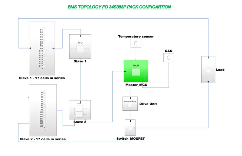
>> Above Model is For the BMS Topology of 34s358P battery pack Configuration model
>>This Topology consists a 2 numbers of the slaves of AFU units with each AFU unit's slave Consisting of 17 numbers Of Cells connected in series.
2. Build a 3S2P battery pack configuration with generic battery block using Matlab/Simulink.
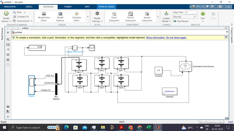
Nominal voltage of cell = 3.6v
Rated capacity of cell =3.5Ah
Maximum voltage of cell =4.2v
Total number of cells in a battery pack = no.of cells in series * no.of cells in parallel
= 3*2 = 6 cells
Nominal voltage of the battery pack = no.of cells in series * nominal volatege of a cell
Nominal voltage of the battery pack = 3*3.6v = 10.8v
Rated capacity of battery pack = no.of cells in parallel * Rated capacity of a cell
= 2*3.5
Rated capacity of battery pack=7Ah
Overall voltage of the battery pack=maximum capacity of the cell*no.of cells in series
=4.2*3
Overall voltage of the battery pack =12.6v
Capacity: The capacity of a battery or cell is defined as the amount of energy that it can deliver in a single discharge. Battery capacity is normally specified in amp-hours (or milli-amp-hours) or as watt-hours.
Charge rate or C-rate : The definition of the charge rate or C-rate of a battery or cell is the charge or discharge current in Amperes as a proportion of the rated capacity in Ah. For example, in the case of a 500 mAh battery, a C/2 rate is 250 mA and a 2C rate would be1 A.
Constant-Current Charge: This refers to a charging process where the level of current is maintained at a constant level regardless of the voltage of the battery or cell.
Constant-Voltage Charge: This definition refers to a charging process in which the voltage applied to a battery is held at a constant value over the charge cycle regardless of the current drawn.
Cycle Life: The capacity of a rechargeable cell or battery changes over its life. The definition of the battery life or cycle life of a battery is number of cycles that a cell or battery can be charged and discharged under specific conditions, before the available capacity falls to a specific performance criteria - normally 80% of the rated capacity.
Cut-off voltage: As a battery or cell is discharged it has a voltage curve that it follows - the voltage generally falling over the discharge cycle. The definition for a cell or battery of the cut-off voltage cell or battery is the voltage at which the discharge is terminated by any battery management system. This point may also be referred to as the End-of-Discharge voltage.
Energy Density: The volumetric energy storage density of a battery, expressed in Watt-hours per litre (Wh/l).
Power Density: The volumetric power density of a battery, expressed in Watts per litre (W/l).
Rated Capacity: The capacity of a battery is expressed in Ampere-hours, Ah and it is the total charge that can be obtained from a fully charged battery under specified discharge conditions
Self-Discharge: It is found that batteries and cells will lose their charge over a period of time, and need re-charging. This self-discharge is normal, but various according to a number of variables including the technology used and the conditions. Self-discharge is defined as the recoverable loss of capacity of a cell or battery. The figure is normally expressed in a percentage of the rated capacity lost per month and at a given temperature. The self-discharge rate of a battery or cell is very dependent upon the temperature.
Specific Energy: The gravimetric energy storage density of a battery, expressed in Watt-hours per kilogram (Wh/kg).
Specific Power: The specific power for a battery is the gravimetric power density expressed in Watts per kilogram (W/kg).
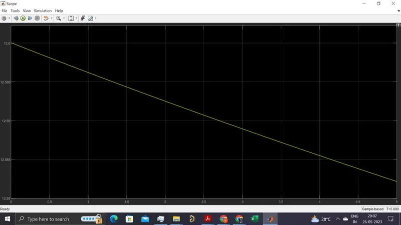
Results :
After running the model the voltage like shown below