Project 1
AIM - Given below is a plan view of a framing layout of a typical school classroom. Design beam marked B1 and the floor slab per IS 456-2000. Use M25 concrete and Fe 415 steel. Use 20 mm clear cover for slab and 30 mm clear cover for beam. Consider a 2.5 kN/m2 super imposed dead load accounting for floor finish and ceiling.
Solution -
To check if the slab is one way or 2-way
Lx/ly = longer dimension / shorter dimension = 8/3 = 2.6 »2 hence its one way slab.
Let's consider slab to be 100mmThickneds
Now dead load from slab = 0.1x25 = 2.5kn/m2
Assuming live load =2 kn/m
considering 2.5kn/m2 for floor finish and ceiling
Ultimate load = 1.5 [5+2] = 11.25Kn/m
DISTRIBUTION FACTOR
Stifness
K= 3/L1/3/L1+4/L2 = 3/8/ 3/8 + 4/8 = 0.42 → kb [left]
K= 4/L1/4/L1+3/L2 = 4/8/ 3/8 + 4/8 = 0.58 → kb [right]
Similarly joint C
Kc → 0.58 [left]
Kc → 0.42 [right]
Now lets find fixed end moment
Distribution factor
Consider grade of concrete and steel = m25 and fe 415
Clear cover for slab = 20mm
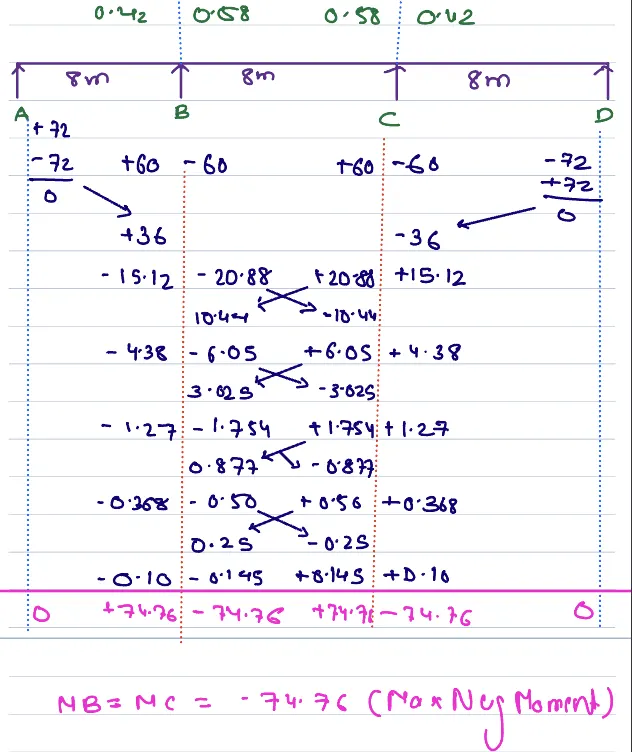
Max moment = 74.76 knm
Assume dia of bar = 8 mm
Effective depth = D - c/c- bardia/ 2
= 100 - 20- 8/2 ( assume did of bar 8 mm)
= 76mm
Limiting moment of resistance [mulim]
[ we use this to check if sectionis depth sufficient and section is under r/f]
If Mulim >mumax we need to change section depth
Mulim = 0.138fckbd2
= 0.138x30X1000 x176X176= 199.27knm
So the moment we have is less than Mulim
Depth is sufficient.
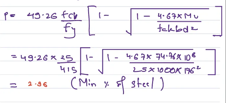
Percentage of steel
Spacing
P = 3.14x bardia2/ 100/45D
= 3.14 x8 x 8/ 100 / 2.96x76
= 37.57mm approx 120mm [ min spacing 120mm]
Therefore provide 8 mm@ 120 mm c/c
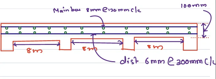
Reinforcement detailing for slab
1- c/c spacing between main reinforcement bar < Max [ 300, 3d ] ref 26.3.3 IS456
Here 120 mm which is less than 300mm and 3x76= 228mm hence safe
2-c/c spacing between dist reinforcement bar < Max [ 450, 5d ] ref 26.3.3 IS456
Here 300 mm which is less than 450mm and 5x76= 380mm hence safe
We assume 6mm@ 300mm c/c
3- min dia of main bar = D/8 Ref 26.5. 2.2 is 456
100/8 = 12.5 we provided 8 mm hence okay
4 - min r/f in slab ref 26.5. 2.1 IS456
0.15% for fe 250 and 0.12 % fe 415 or 500
Lets calculate spacing to check it 300mm spacing that we provided for dist bar is okay or not
S= 3.14/4 x diabar2 x 100/ 0.12d
= 3.14/4 x 6X6 x100/0.12x176 = 133.87mm = 300mm
Hence okay 26.3.3 is456
REINFORCEMENT DETAILING DIA
- Beam design
Solution - beam width = 23mm, beam depth = 300mm
Let cover = 30mm [ table 16 IS4S6 ]
Area load acting on beam = 3xwu
Weight of slab on beam = 25X0.1 = 2.5kn/m [per m width ]
Live load = 2kN/m
Dead load of beam = 0.23x03x25 = 1.73 kn/m
Ultimate load =1.5 x[7]= 10.5 kn/m
Area load acting on beam = 3x 10.5 = 31.5
Total ultimate load = 31.5 +2.6 = 34.1 kn/kN/m
Stifness
K= 3/L1/3/L1+4/L2 = 3/8/ 3/8 + 4/8 = 0.42 → kb [left]
K= 4/L1/4/L1+3/L2 = 4/8/ 3/8 + 4/8 = 0.58 → kb [right]
Similarly joint C
Kc → 0.58 [left]
Kc → 0.42 [right]
Now finding fixed and moments
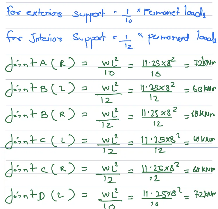
For exterior supp = 1/10 x permanent loads
For interior supp = 1/12 x permanent loads
Joint A (r) = WL^2/10 = 34.1x8X8 /10=218.2knm
Joint B (l) = WL^2/12 =34.1x8X8 /12= 181.66knm. Joint B (r) = WL^2/12 =34.1x8X8 /12= 88knm. Joint C (l) = WL^2/12 =34.1x8X8 /12= 88knm. Joint C (r) = WL^2/12 =34.1x8X8 /12= 88knm Joint d (l) = WL^2/10 =34.1x8X8 /10= 105.6 knm
Moment distribution as follows
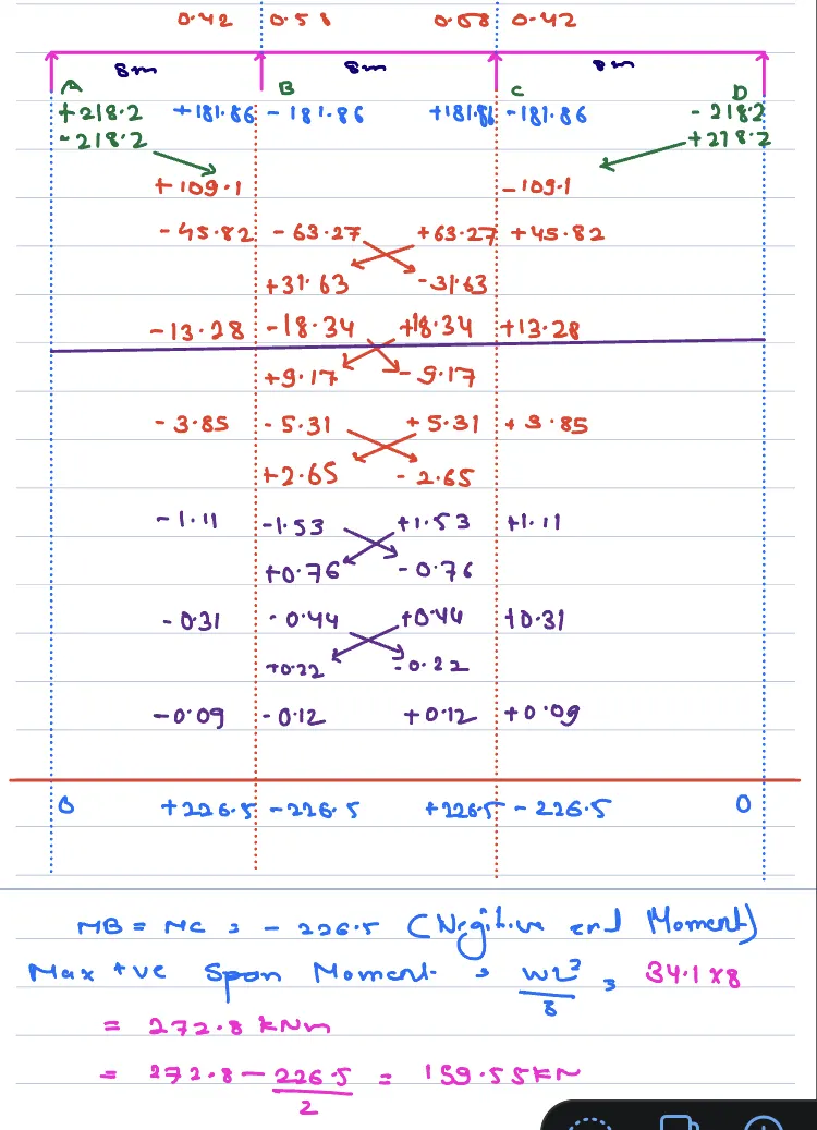
Mb = mc = - 226.5knm [ Max -ve moment]
Max positive moment = wxlxl/ 8= 34.1x8 x 8/8= 272.8 KNM
= 272.8 - 226.5/2 = 159.55kmm
Design of beam
bf = Lo / 12 +bw+ 6Df
Lo: [distance between point of zero moment] = 0.7*8000
Lo = 5600 mm
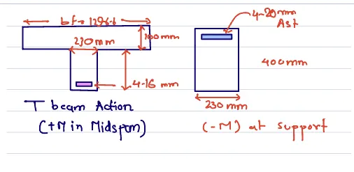
Bf = 5600 / 12 +230 +100X6 = 1296.6mm
Note - bf shall be less of min of 1296.6mm or 0.5 of effective
tributery area = 0.5 x [8000+3000]=5500 mm Hence bf = 1296.6 mm
Now designing of beam
C/C =30mm, grade steel and conc - fe415 and M30
Effective depth= D - c.c - dia of bar / 2 = 500-30-12/2 = 364mm
Xumax = 0.48 x 364 = 174.72mm
MuliM [ - ve ]= 0.138 fck bxd2 = 0.138 x 25x 230 x 364 x 364 = 288.8knm
This is greater than the Max demand hence section depth is sufficient
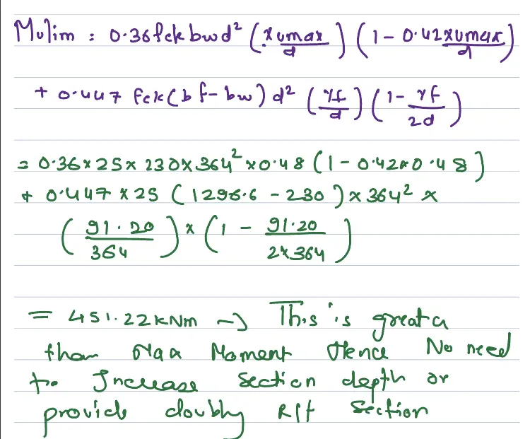
MuliM [ + ve ] = df /d = 100/364 = 0.27> 0.2 hence case 2 is applicable
Yf = 0.15 xumax + 0.65Df = 0.15x 174.72+ 0.65x100 = 91.20Mm
Mulim calculation ↓
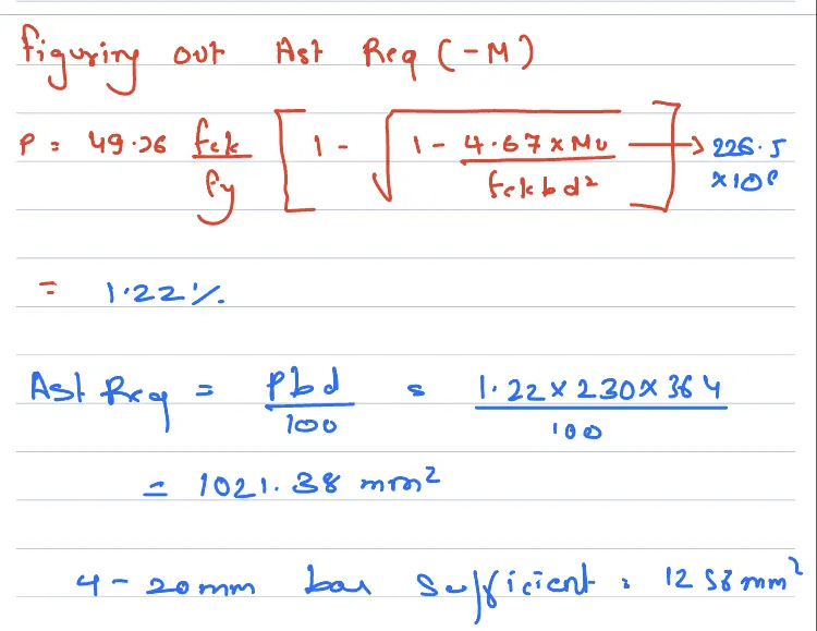
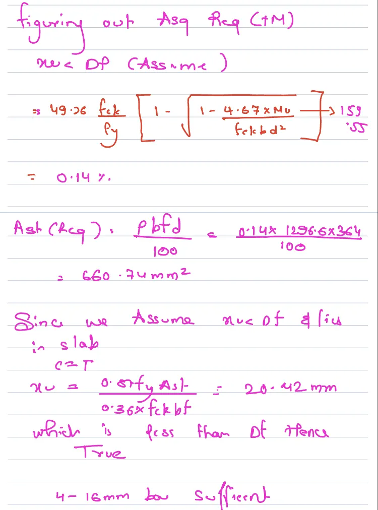
figuring out % of steel and area of steel req For positive and negative moment
Negative moment ↓
positive moment
ReinForcement detailing
Min rF [rect] = 0.87 xbd / fy = 0.87 x 230x364 / 415 = 175.50 mm2
Man rF [T beam] = 0.87 xbfd / fy = 0.87 x 1296.6x364 / 415 = 989 mm2
Max rf = 0.04 bD = 0.04 x 230 x 400 = 3680mm2 [ rect ]
Max rF = 0.04bfD = 0.04 x 1296.6 x 400 = 20746 mm2 [t beam ]
Steel req due to flexure demand + m[ t beam ]= 660.74 mm 2
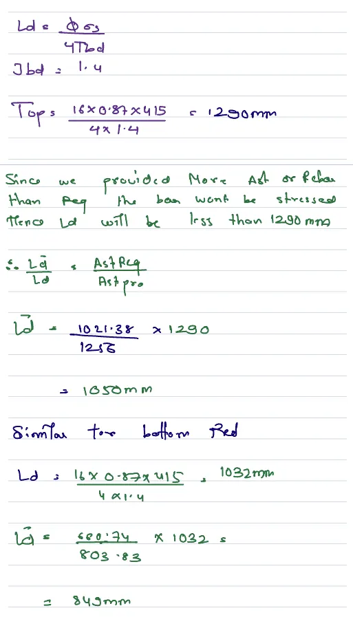
Steel req due to flexure demand -m [ rect] = 1021.38mm2
Rect = 4- 20 mm bar top = 1256 mm2
T beam =4-16mm bar bottom = 803.83 mm2
Development length
Detailing of beam