Project 1
AIM:
Q.1. Design a battery pack for a car roughly 150 Kw with 120 V. Use 3500 mAh 3.6V nominal NMC chemistry cell.
a. Design the battery pack configuration.
b. Draw the BMS topology for this battery pack.
ANS:
Design of Battery Pack Configuration:
Given data,
Required power= 150 kW and voltage of 120V
Nominal voltage of each cell = 3.6V, Capacity of each cell = 3500 mAh
Number of Cells in Series:
First, let's determine the number of cells required in series to achieve a nominal voltage of 120V:
Nominal voltage of each cell = 3.6V
Number of cells in series = Total voltage of battery pack / Nominal cell voltage
Number of cells in series = 120V / 3.6V = 33.33 (approx. 34 cells)
Number of Cells in Series:
Next, let's determine the number of cells required in parallel to achieve the desired capacity:
Capacity of each cell = 3500 mAh
Required total capacity of the battery pack = 150 kWh (or 150,000 Wh)
Number of cells in parallel = Required capacity / (Nominal capacity of a single cell x Number of cells in series)
Number of cells in parallel = (150000 W / 120 V) / (3.5 Ah x 34) = 14.39 (approximately 15 cells)
Therefore, the battery pack configuration would be 34 cells in series and 14 cells in parallel, resulting in a total of 476 cells.
BMS Topology for given battery pack:
- A battery management system (BMS) is an electronic system that is responsible for monitoring and controlling a battery pack's operation. In a master-slave BMS topology, the system is divided into two parts: a master module and multiple slave modules.
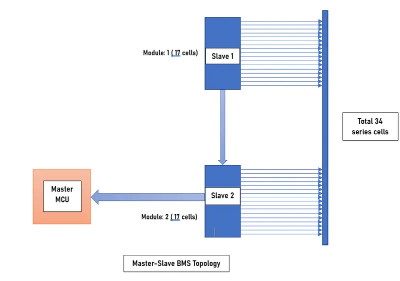
- In the case of a battery pack with 34 cells in series, the master module is responsible for monitoring the overall battery pack voltage, current, and temperature. The slave modules, on the other hand, are responsible for monitoring the voltage and temperature of each individual cell in the pack.
- The master module communicates with the slave modules through a communication bus, such as a CAN bus. The communication between the master and slave modules allows the BMS to monitor and control the battery pack's operation as a whole.
- The master module is typically a more powerful microcontroller or processor that can handle the complex calculations needed to manage the battery pack. It also contains the firmware that controls the BMS's operation and communicates with the vehicle's main controller.
- Each slave module monitors the voltage and temperature of a group of cells, typically 3-8 cells per module, depending on the specific BMS design. The slave modules report this information to the master module, which then uses it to determine the overall state of the battery pack.
- In addition to monitoring the cells' voltage and temperature, the BMS also controls the charging and discharging of the battery pack. The BMS uses information from the slave modules to balance the cells' charge levels, ensuring that no cell is overcharged or over-discharged, which can lead to damage or failure.
Overall, the master-slave BMS topology provides an efficient and effective way to manage large battery packs with multiple cells in series. It allows the BMS to monitor and control the battery pack's operation as a whole while still providing detailed information about each individual cell's performance.
Q.2. Build a 3S2P battery pack configuration with generic battery block using Matlab/Simulink.
ANS:
3S2P battery pack configuration:
To build a 3S2P battery pack configuration using Matlab/Simulink, we first need to define the characteristics of the generic battery block.
For this example, let's assume that each battery block has the following specifications:
- Voltage: 3.6 V
- Capacity: 3.5 Ah
Now, let's proceed with building the battery pack configuration:
Battery block:
Open a new Simulink model and add a battery block from the Simscape library.
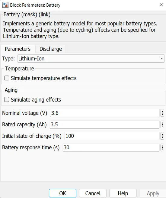
Double-click on the Battery block and set the following parameters:
- Nominal Voltage: 3.6 V
- Nominal Capacity: 3.5 Ah
Simulink modelof 3S2P battery pack configuration with generic battery block:
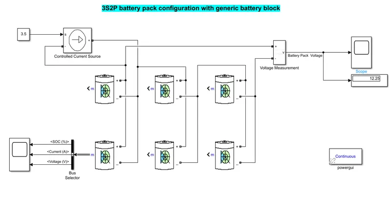
- The 3S2P battery pack model is as in shown below.
- The voltage measurement block is connected across the battery pack to measure the battery pack voltage.
- The controlled current signal is given as the load to the battery pack with the help of constant block which is connected as input to the controlled current source.
- The scope block is used to get the battery parameters like SOC, Voltage and Current of the battery.
Output Plot:
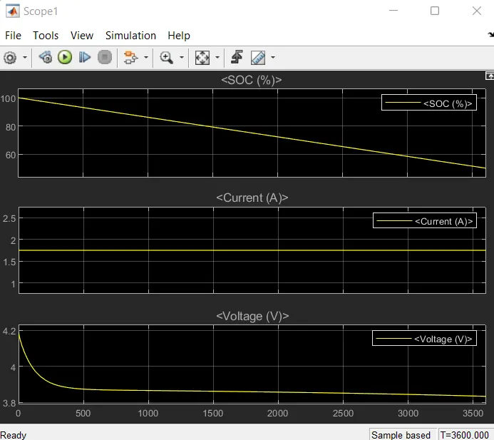
- The scope block shows the output of battery pack and each cell level parameters as shown below.
- Initiallly the SOC of battery is 100%, and it decreases to below 60% with given load conditions.
- The voltage of the battery is 4.2V and then it decreases to 3.85V as per the given load.
- The current in the battery is constant at 1.75Amps , it may decreases during regenrative braking.
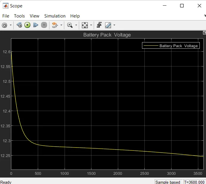
The below graph shows the initially the battery pack voltage is 12.6V and then it goes down due to load conditions till 12.25V, it increases during regenerative braking.
CONCLUSION:
Hence, we have successfully build the simulink model for 3S2P battery pack configuration and run the simulation and analyzed the different battery parameters behaviour during the load conditions.