Project 1
Aim- To route the wiring harness on given Engine and flatten view drawing in CATIA V5.
Objective- The objective of the project is to route the wiring harness on given Engine and prepare flatten view drawing in CATIA V5. All types of packaging rules have to be considered while routing the harness. Also, Industry best practices should be demonstrated in design. All the necessary details like clearance, clipping/clamping selection, harness fixing requirements, harness continuity should be provided in order to design wiring harness.
Engine Harness
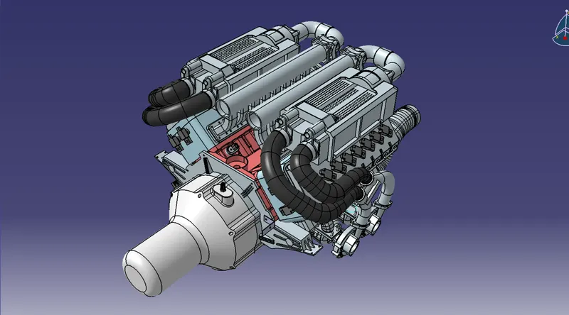
- The above figure shows the 16 valve Bugatti Engine where 8 cylinders are placed on the right side and 8 cylinders are placed on the left side.
- There are total 16 injectors where 8 injectors are used for 8 cylinders on right side and 8 injectors are used for another 8 cylinders on left side.
- Also there are 4 cam-shaft sensors, so there are total 20 sensors that we have to connected electrically.
- Generally, 4-pole connectors are used for fuel injectors of the engine.
- The engine will also have an interconnection connector which will connect the engine to other parts of the vehicle. We will be using a 12-pole electrical connector with a mounting clip feature as an interconnection connector.
- The plastic guiding channel used in this harness should bemade of a material that can withstand at least 150 degree Celcius.
- The bend ratio for the all bundle segmets should be 1.4
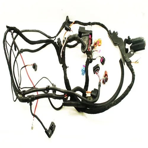
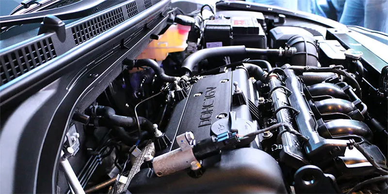
An engine wiring harness is constricted wires, cables, terminals, and connectors controlling a vehicle’s electrical system. It relays electrical power and control information to components such as batteries, alternators, fuel injectors, fuses, audio systems, blower motors, fuel injectors, and computers. Wire harness companies customize it for every location, application, and design it interconnects. Also known as a cable harness, it is more than just a collection of multiple wires put together.
It manages the key functions around the engine including engine controller, oil controller gate, transmission plug housing, air pipe sensors, pressure sensors, and water temperature sensors.
An engine wiring harness is how each part of your vehicle gets electricity. It is crucial to help the vehicle run and it’s usually made of a heat-resistant rubber to handle the high and low temperatures that vehicles often experience. The vehicle needs more than the engine, and it requires a lot of electricity for certain things to function, like the radio or lights. Beyond that, battery, starter, and even alternator run on power, which is provided by the engine. Without an engine wiring harness, we couldn’t start your vehicle.
Engine Wiring Harness protection
Protecting the wires is crucial to the safety of the vehicle. Wires exposed to high temperatures, erosive chemicals and projectiles will be damaged leading to fires, brake failures and critical malfunctions. To prevent these issues, wires need to be bundled and covered.
install wiring insulation or heat shield sleeve material that can withstand direct contact with high-temperature surfaces and is flameproof. It needs to be a material built specifically for under hood automotive applications and withstand constant temperatures up to 125°C, or 257°F.
There are many options for protecting the wires in a vehicle’s harness. Zip ties securely bundle wire together but offer little protection or insulation. Plastic conduits offer protection from rough surfaces, although they can add weight and are not as flexible as other options. Heat-shrink tubing provides protection from heat, moisture and chemicals. However, the application is time-consuming.
Tape is another option for bundling and protecting wires. Tapes are more flexible and cost-effective than other bundling options because they can be used for protective wrapping, bundling and sealing. With a wide variety of backings and adhesives, tape can offer sound dampening, thermal and electrical insulation and abrasion protection of the same quality of the other methods. Additionally, tapes are more flexible, lighter and easier to apply than tubing or plastic conduit.
DESIGN METHODOLOGY
Step 1- download the engine CAD data and required connectors CAD data from the given source.
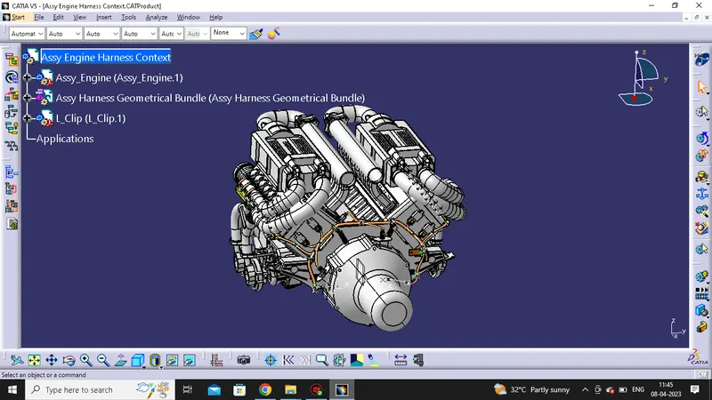
Step 2- Download the required Connectors from the source and convert the mechanical connectors electrically by using the electrical part design work bench by following below steps.
- First download the connectors and mounting clip from the given link source.
- Get into the mechanical part workbench to create required geometrical parameters. Create connector connection point and bundle connection point on the required sides of the CAD part.
- Create axis system on the connector connection point such a way that the Y coordinate facing normal to the connector face, X coordinate facing towards the locking mechanism and Z coordinate facing to the top.
- Create cavity connection point for connectors having the cavity for mounting clips
Using the geometrical parameters created,
- Define part as electrical connector.
- Define bundle connection point.
- Define connector connection point.
- Define cavity connection point.
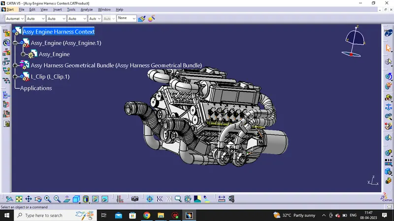
STEP 3- Download and Define the plastic channel electrically
- Procedure for electrically defining the Channel.
- Create bundle entry point and exit point.
- Create a line curve between the main entry and exit points for creating the multi-branchable using external curve inside the channel
- Create 8 bundle entry points on the openings for connecting the injector connectors.
- Using the geometrical parameters, define the channel electrical using the define mounting equipment option.
- Create define bundle entry points using the “define bundle connection point option.”
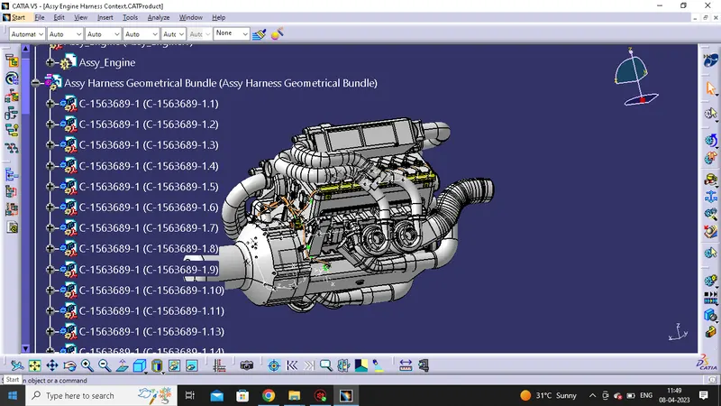
WIRING HARNESS FLATTENING
Create a new product file for flatten the wiring harness and save as in the same folder where the wiring harness is saved. Then switch to Electrical harness flattening workbench and select harness flattening parameters and define harness flattening parameters. Before creating flatten view, Make sure that selecting 'Double line' for bundle segment and 'Double' line for protective covering.
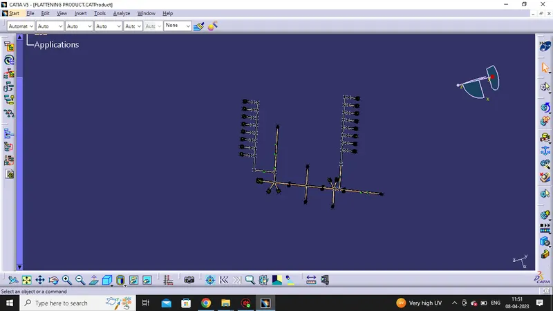
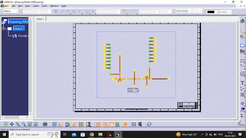
drawing of the flattened wiring harness
open a new drawing file and Select front view command, then go to the flattened harness window and select a suitable face to create drafting of the harness.
to make the bundle segments visible right click on the drawing sheet and go to properties, in the view tab, highlight '3D wireframe' and 'is always visible' in the dress up settings.