Project 1
Aim:
To investigate the given site condition of the proposed bridge construction. And to choose the more suitable bridge form superstructure. To model the form in LUSAS with all given loadings of train & shown imposed loads.
Calculation of total horizontal length required for the bridge to connect two abutements:
Converting the inclined roadway & river allignments into a straight line as follow,
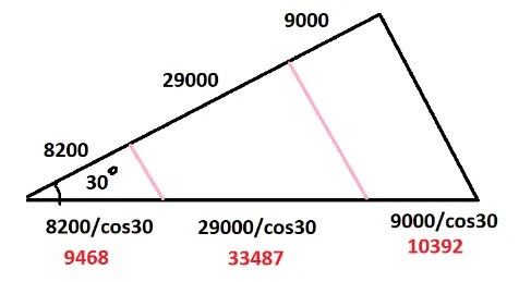
On the left side 50 meter and on the right side we have 50 meter of bridge length. So in total, the bridge length would be 50+9.5+33.5+10.5+50= 153.5 meter
To finalyze the bridge form, the tentative support locations need to be figured out. The below is the redefined sketch of bridge path.
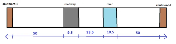
One support/pier shall be positioned in between roadway and river. In this case, the bridge will have only two segments with longer spans. So, two more supports/piers are proposed each adjacent to the roadway and the river. Keeping the internal span as 'L' and end span as '0.65L', the spans of the bridge will be 0.65L+L+L+0.65 = 3.3 L
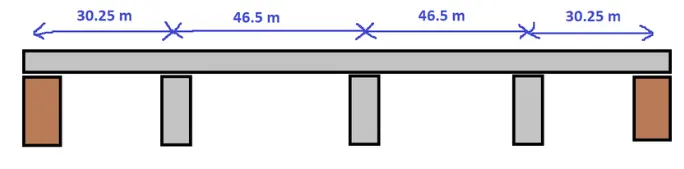
Dividing it by the whole length, we get L = 46.5 meter. The final bridge spans shall be as follows.
Choosing the bridge form:
The following conditions need to be addressed before choosing any bridge form,
1. Since the bridge carries dual railway track, the presence and absence of any individual track will create torsion in the bridge structure.
2. The span of bridge coming around 50 meter.
3. Since the bridge is passing over a river, it is impossible to provide formwork & shuttering on river.
4. Since the bridge is passing over a roadway, it may be costlier to block the roadway for some days to cast the bridge decks.
5. The height clearance required for the roadway is 5.3 meter. The top of railway track is at 8.5 meter. So it should be ensured the entire deck thickness + non structural elements combined having overall depth less than 3 meter.
6. From the elevation given in question, we can understand 650mm is already filled up by gravel & non structural slab. So the remaining 2.35 meter depth only is allowed for structural bridge deck section.
7. Since it has a dual railway path, it will definitely influenze torsion in the bridge section. The bridge form should be compatible in addressing torsional effects.
Considering all the above conditions, it is decided to go with Precast segmental Box girder deck for the proposed bridge construction.
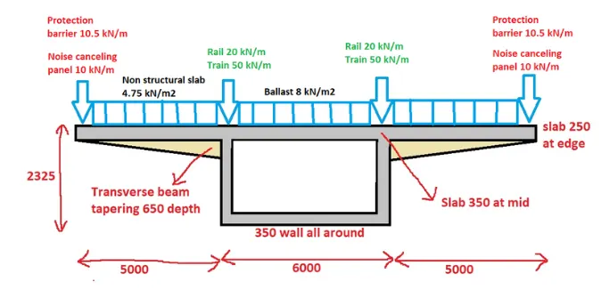
Calculation of super dead loads & live loads over structural bridge deck:
- non structural slab 250mm thick at end and 130mm at mid giving average of 190mm thick x 25 = 4.75 kN/m2
- noise cancelling panel 10 kN/m x 2 = 20 kN/m
- protection barrier 0.3x1.4x25x2 = 21 kN/m
- ballast of 20 kN/m3 density 400mm thick = 8 kN/m2
- Track rail load 20x2 = 40 kN/m
- Train load 50x2 = 100 kN/m
Initial sizing of box girder:
1. Single cell box girder can be used upto 16 meter of deck width
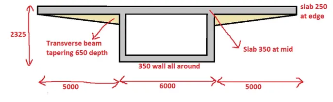
2. The average span to depth ratio to be adopted for L/20, which will give 46500/20 = 2325mm
3. Assuming the wall and slab thickness to be 350mm.
4. Adding transverse beams below the slab since the cantilever length of slab is longer. The depth of beam shall be taken as 650mm in the initial trial. keeping them at 5 meter interval with 350mm width.
5. Also diaphragms are provided at all support sections with the same 350mm thick wall.
Loading assumption on bridge deck:
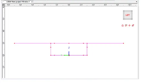
Modeling with LUSAS:
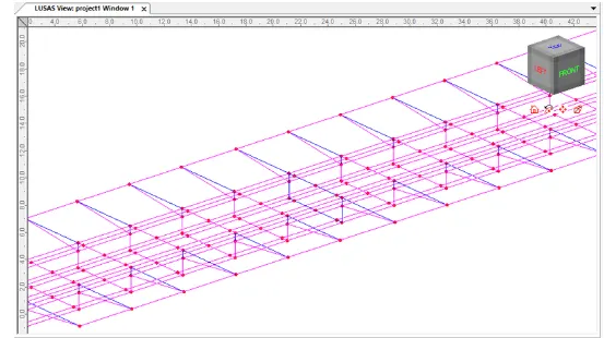
Creating the nodes & outlines of the box girder section in LUSAS. Assuming the two supports below box girder, the nodes have to be predefined in the line modeling.
Swapping the line section into spans required as per project
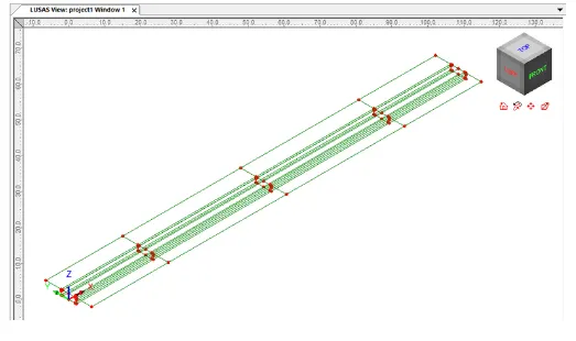
Adding intermediate transverse stiffener beams at 5 meter interval.
Adding diaphragms at all support sections.
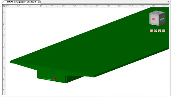
Assigned surface mesh, material, shell thickness
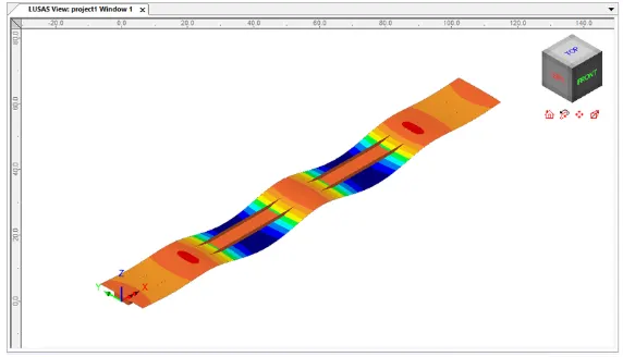
Deformed shape of box girder bridge for SLS-Characteristic combination:
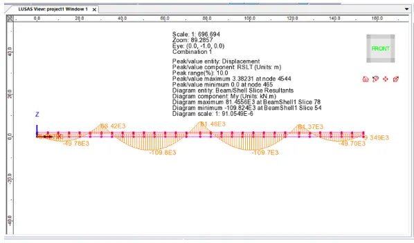
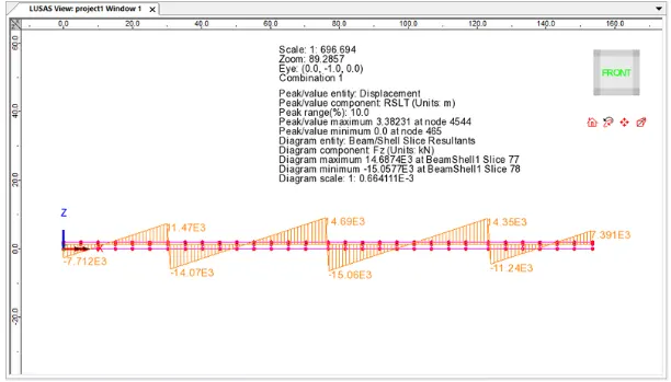
Bridge moment / Shear force sliced diagrams from LUSAS:
Bending moment for SLS-Characteristic combination
Shear force diagram for SLS-Characteristic combination
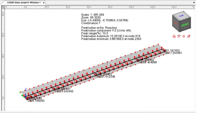
Final reactions (unfactored) at bearings for Pier design purpose: