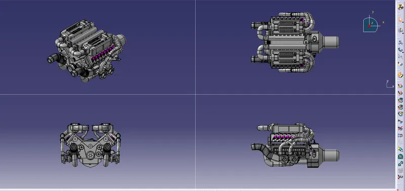
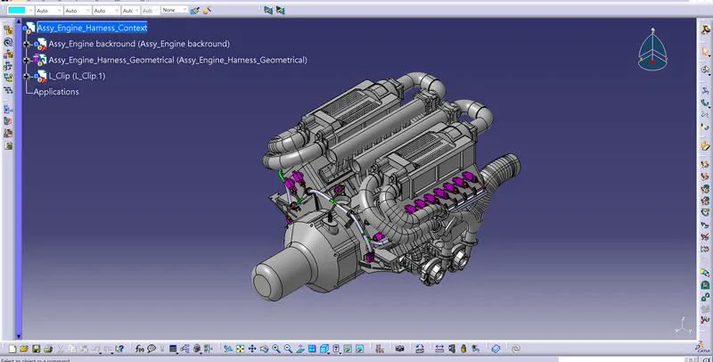
Project 1
Automotive Wiring Harness for Engine
Aim: To create the wiring harness routing along the Engine by considering all the harness design rules using the software CATIA V5.
Introduction:
A device created to transform one or more sources of energy into mechanical energy is known as an engine or motor.
Potential energy, heat energy, chemical energy, electric potential, nuclear energy, and energy from the Earth's gravitational field are some of the energy sources that are now available (from nuclear fission or nuclear fusion). Heat engines are particularly important since many of these processes use heat as an intermediary energy source. Atmospheric convection cells are one example of a natural mechanism that transforms ambient heat into motion (e.g. in the form of rising air currents). In addition to playing a part in numerous industrial operations including cutting, grinding, crushing, and mixing, mechanical energy is particularly crucial for transportation.
Rules to be followed to route the Harness
- Easy manufacturing, installation, removal and maintenance needs to be addressed in designing the wire harness.
- It is important to route the wiring harness so that it is simple to install and access.
- The area around a wiring harness should be free of sharp objects like corners and edges.
- When assembling or servicing a harness, avoid routing and clipping in regions that are difficult to access or in blind spots.
- If more slack is required due to the environment or the harness bending requirement, give it. The envelope dimensions during door opening and shutting should be taken into consideration to allow slack if the harness is going through the closures/doors or tail gates. Here the slack should be between 1 to 5mm.
- When designing the wire harness in the CAD environment, it is important to ensure that there are no instances of fouling. To prevent fouling, additional mounting tools like clips or clamps may be employed.
- Avoid passing through tiny structural apertures and holes. to reduce handling and chaffing when installing the wire harness.
- Use of rubber grommet is recommanded if harness is passing from wet zone to dry zone of Vehicle.
- The branch length should be greater than 50mm.
- The distance between the clip and connector should be more than 25mm.
- The distance between the two branch points should be greater than 50mm.
- Clips/clamps used for the wiring harness should be easily available in the market to avoid extra cost for custom mounting solutions.
- Before routing the componet all the neccessary parts like connctors, clamps, clips and Bacshell should be electrically defined.
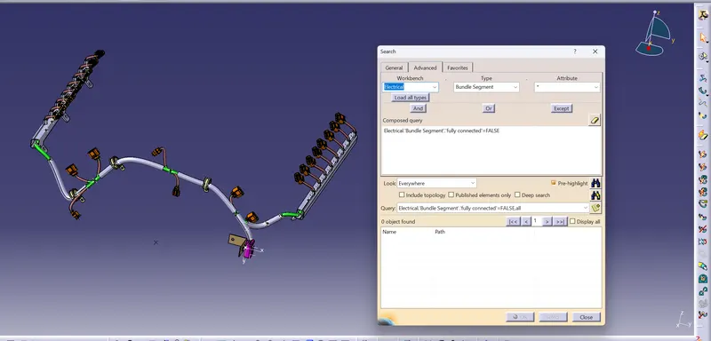
- Check for the bundle continuity.
- Keep harness away from Transmission dynamic assemblies like Drive shaft or propeller shaft.
- Limit the number of branches from single branching point to 4.
Input CAD Data:
Here the input is the Engine and we need to route the budle harness such that,
- we should consider all the design consideration
- Here the engine will be in the hot condition, we should select the connectors and clamps such that it would not get affected
- Also provide the COT tubes and Silicon tubes for the protection so that it can withstand the heat.
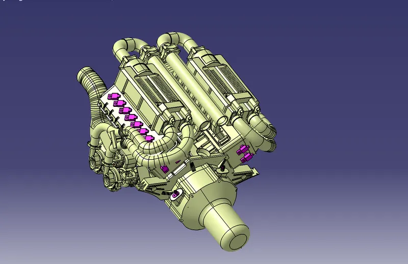
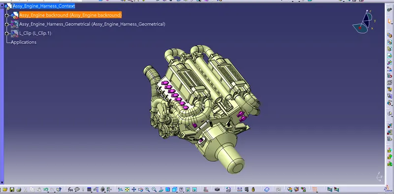
Steps carried out in the catia v5 are as follows,
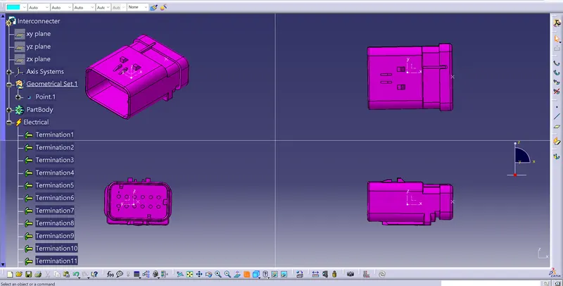
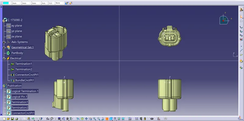
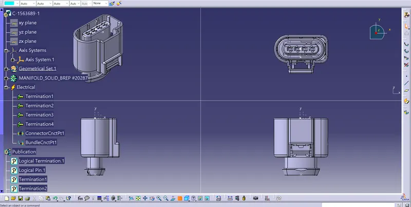
- Download the C-776438-4, C-282080-1, C-1563689-1 and Connectors from www.te.com and Define it as electrically using Electrical part design and copy under Assmy harness bundle
- C-776438-4
2. C-282080-1
3. C-1563689-1
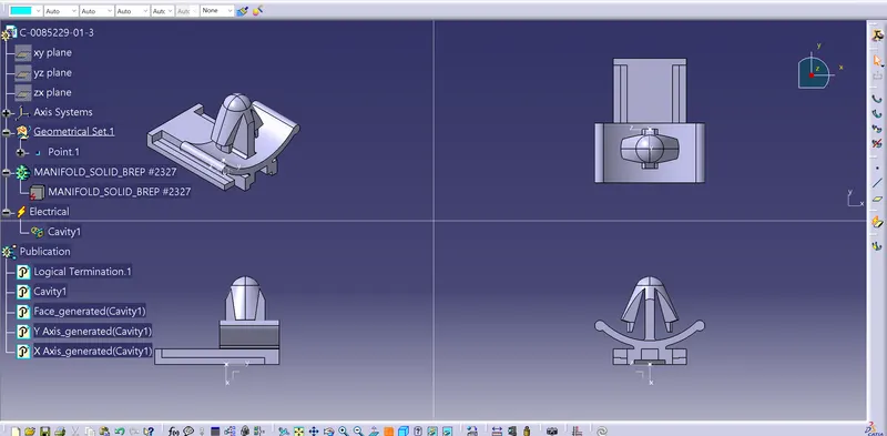
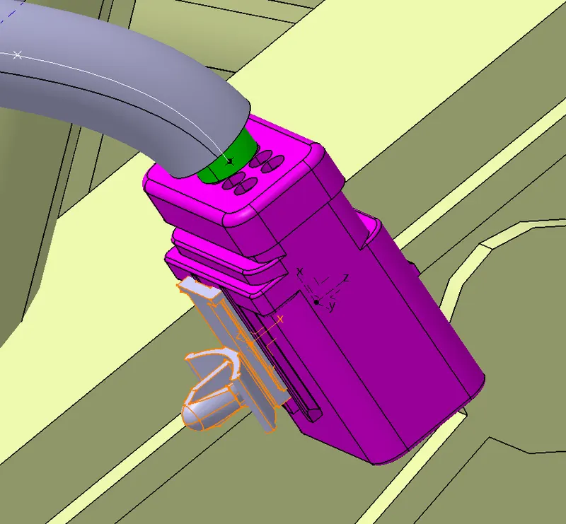
4. C-0085229-01-3
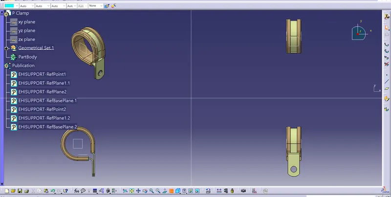
5. P-clamp
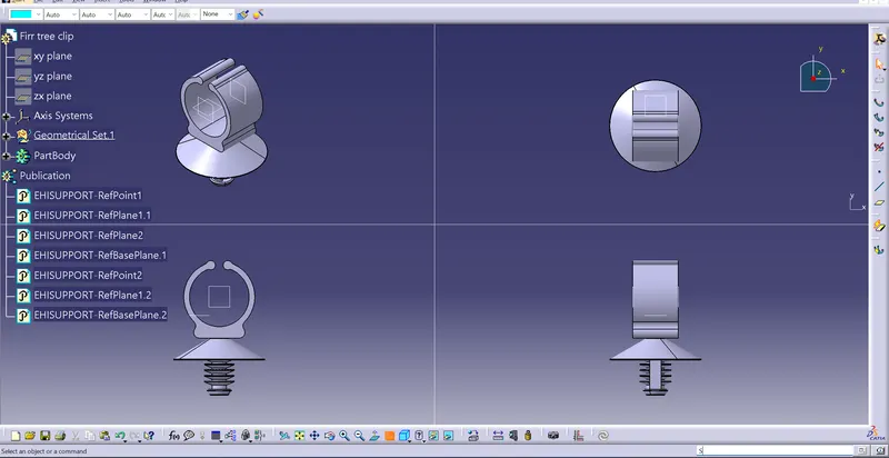
6. Firr_tree_clip
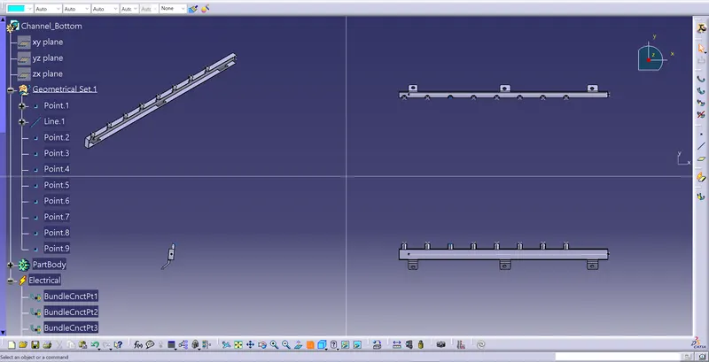
7. Channel bottom
8. L_clip
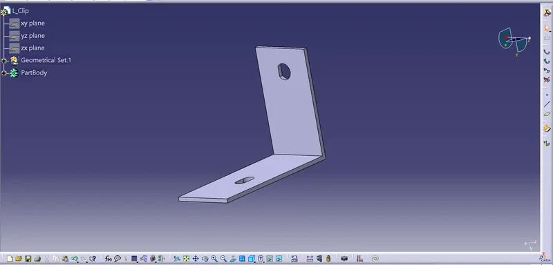
- Place all the connectors and clips on the Backdoor pannel using manipulate, snap and smart move tools in the Assembly Design
- Next is to Bundle harness to the connectors and clips using Electrical Harness Assembly and Main branch diametr is 15/10mm and Sub-Branch is 5mm diameter.
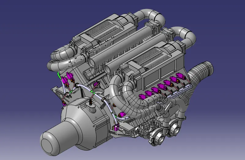
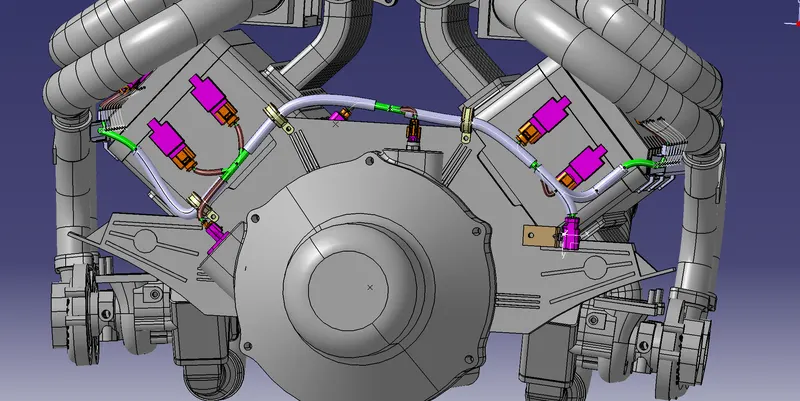
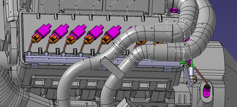
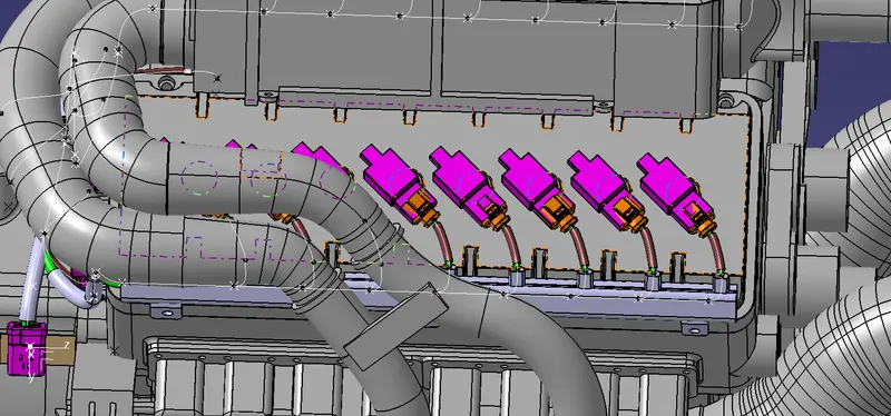
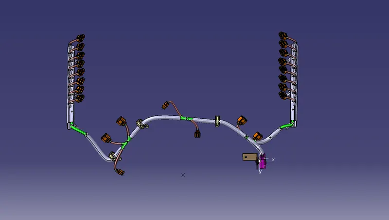
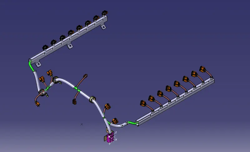
Bundle continuity
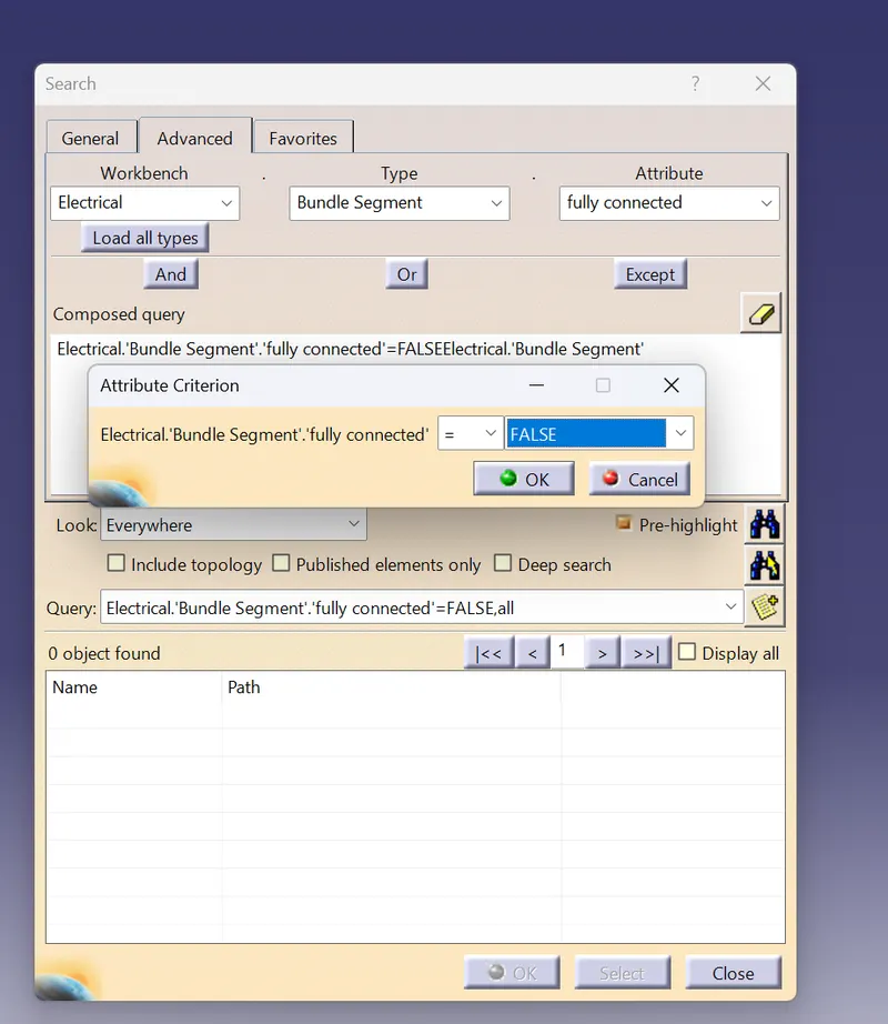
Flattening
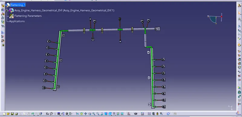
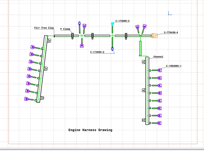
- Then the Bundle harness is flattened from 3D model to 2D model using Electrical Harness flattening workbench.
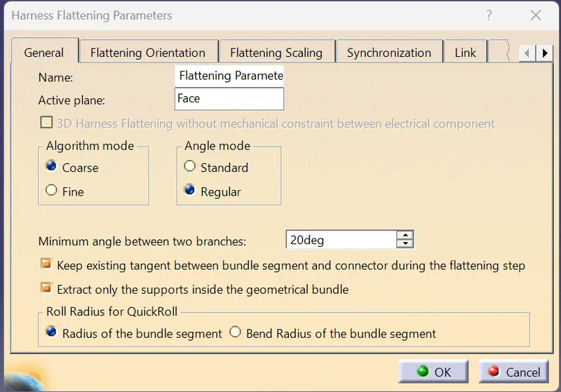
- Use the Harness flattening parameters option to give neccessary parameters for easier Bundle flattening and sis shown in the below fig
- Next, use the extract tool and select the Geometrical Bundle product file from Context assmy file and It will create Ehf file.
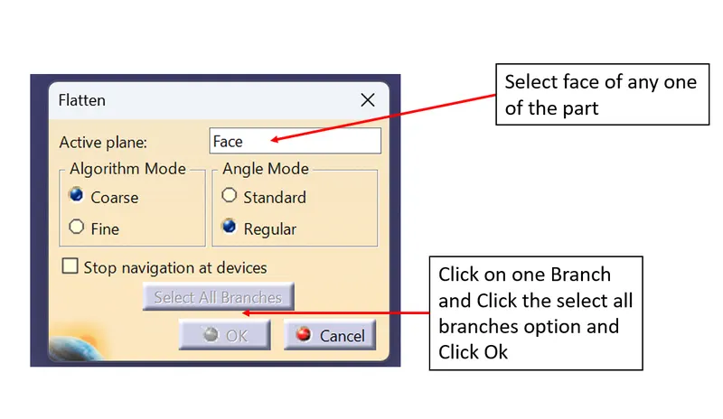
- Then click the flatten option and shown in the below fig.
- Using tools like Rotate, Roll and Scale to create desired flattening
Drawing
- The final step is to create a Drawing sheet to represent 2D model for production purpose.
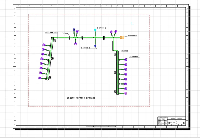
- Save all the product files in one main file by using save management option.
Visualiation of the Product