Project 1
QUESTION-1
The three-phase diode rectifier is supplying approximately 2.2 kW load with VLL=208V at 60 Hz, Ls=1 mH and Cd=1100 μF, where Cd is the DC side capacitor. Design the circuit in one of the simulation platforms (MATLAB or Ltspice/Simetrix) and obtain the circuit waveforms. Based on their simulation studies find out the following:
Circuit diagram;-
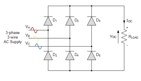
In 3-phase power rectifiers, conduction always occurs in the most positive diode and the corresponding most negative diode. Thus as the three phases rotate across the rectifier terminals, conduction is passed from diode to diode.
Then each diode conducts for 120o (one-third) in each supply cycle but as it takes two diodes to conduct in pairs, each pair of diodes will conduct for only 60o (one-sixth) of a cycle at any one time as shown above.
Therefore we can correctly say that for a 3-phase rectifier being fed by “3” transformer secondaries, each phase will be separated by 360o/3 thus requiring 2*3 diodes.
Note also that unlike the previous half-wave rectifier, there is no common connection between the rectifiers input and output terminals. Therefore it can be fed by a star connected or a delta connected transformer supply.
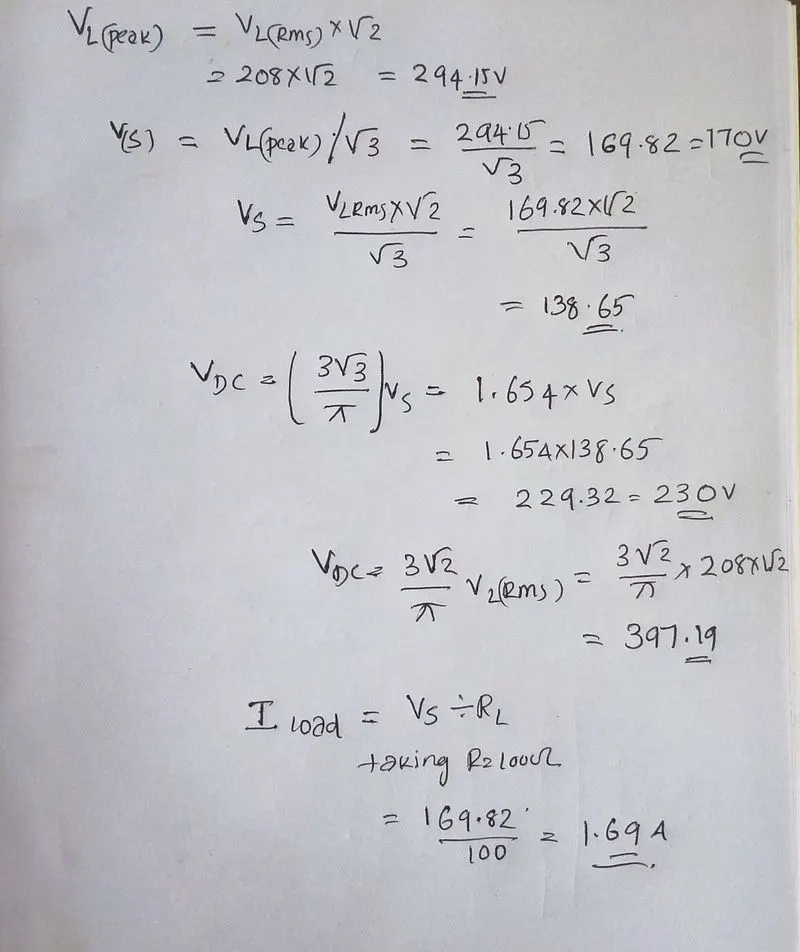
Calculations:-
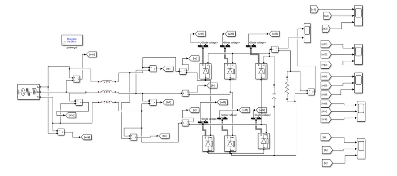
Simulink model:-
Simulink model:-
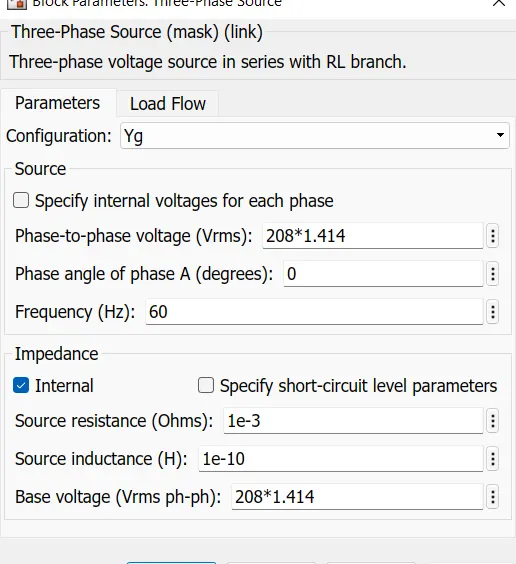
3 phase ac source
load
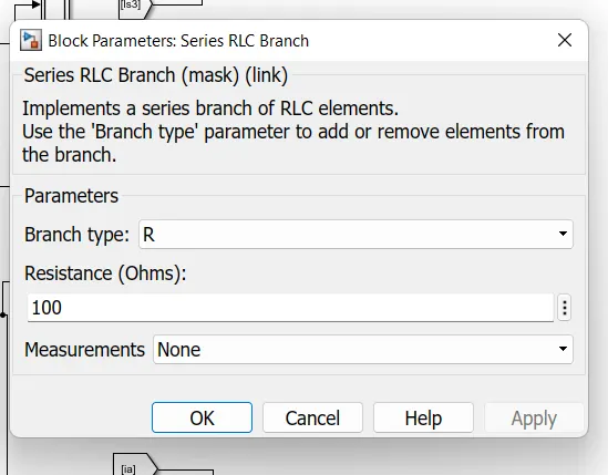
Capacitor
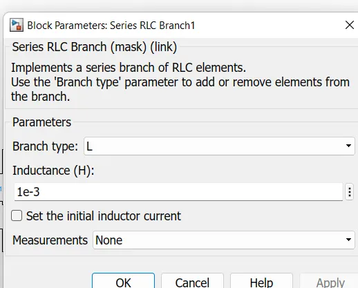
Ls
Results:-
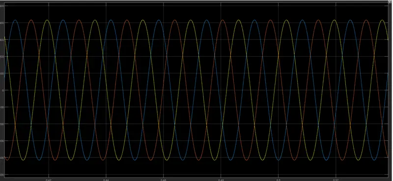
input voltage and current
output voltage and current
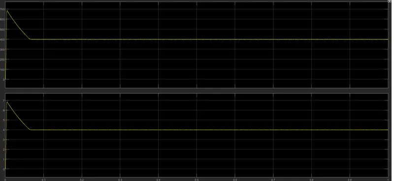
current
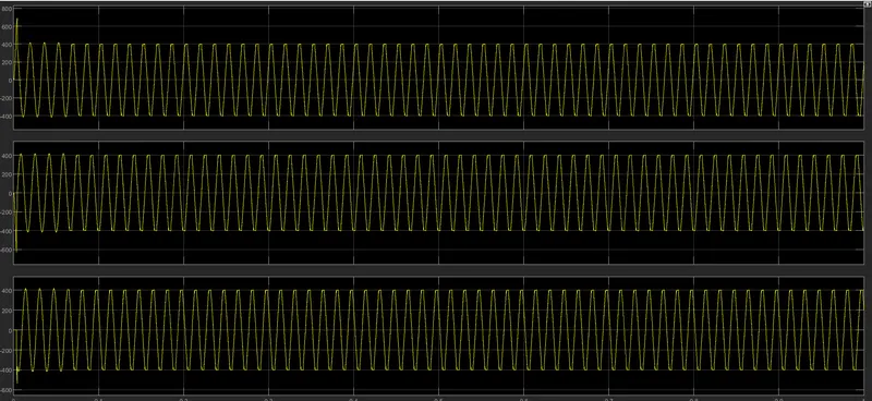
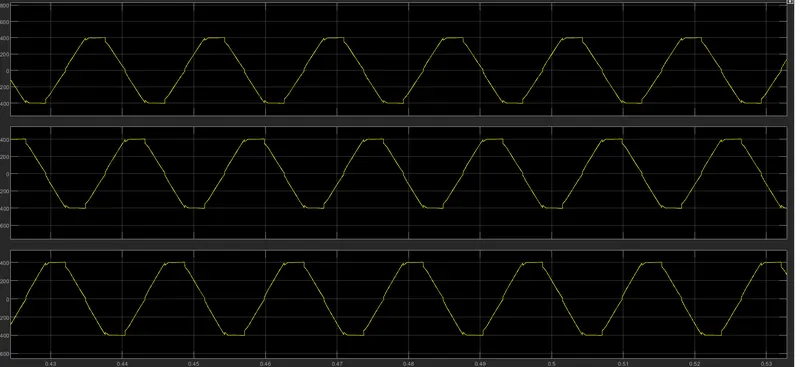
diode voltages
vd1,vd2,vd3
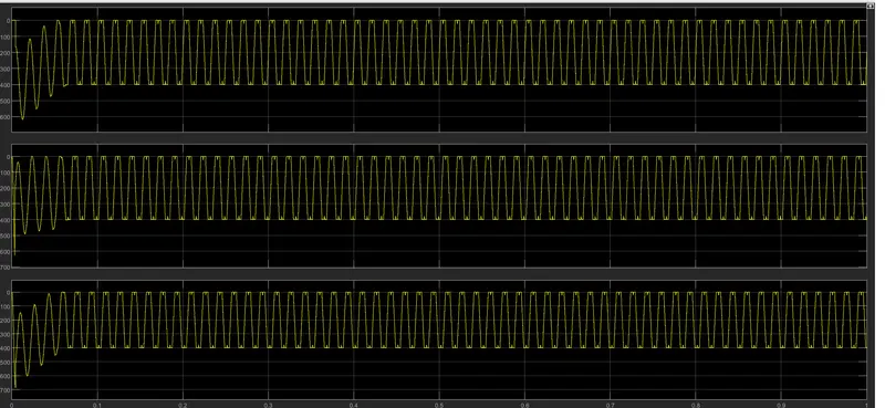
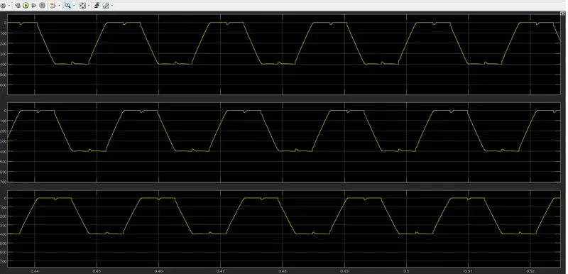
vd4,vd5,vd6
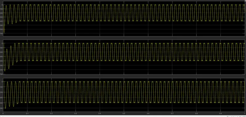
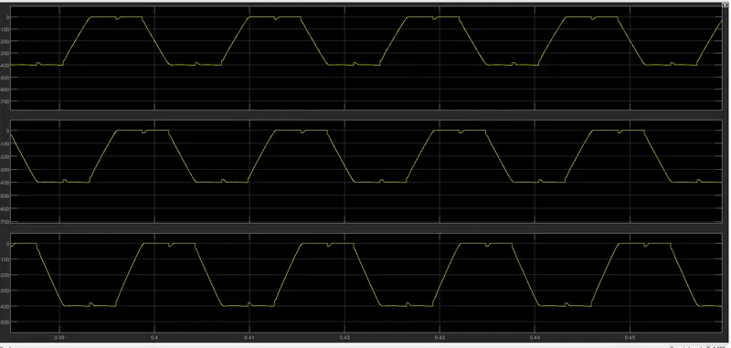
next we need to move on FFT ANALYSIS
FFT ANALYSIS
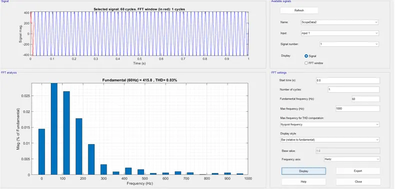
Input voltage
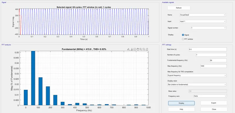
here
THD=0.03%
and fundamental 60hz=415.8
list for 60 hz
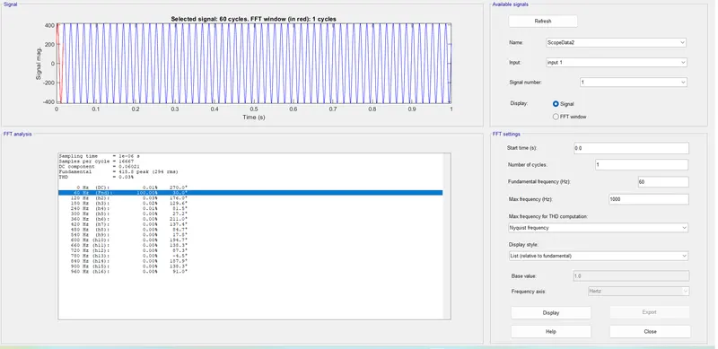
for 60hz it is 30 degree
output
input 1
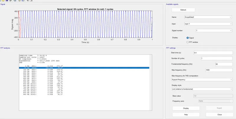
it is 30 deg
input 2
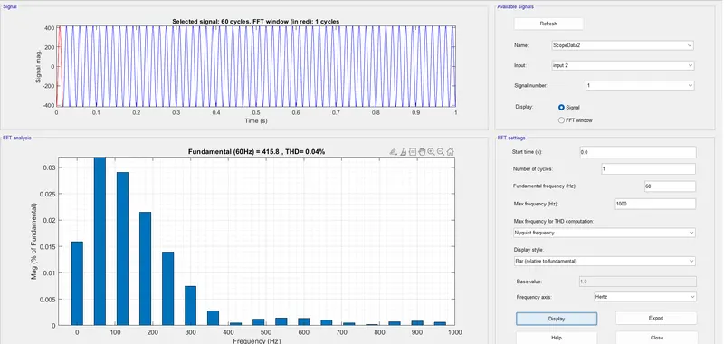
here
THD =0.04%
list
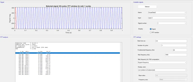
for 60 hz
it is -90 degree
input 3
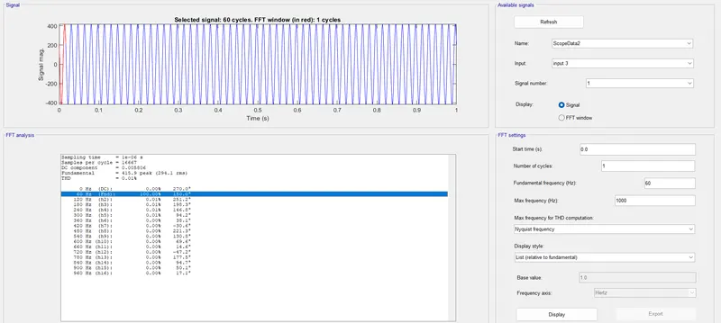
it showing 150 degree
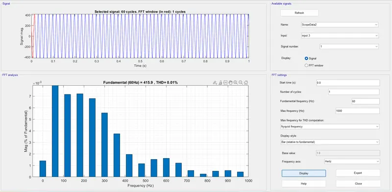
showing THD=0.01%
fundamental=60hz
QUESTION-2
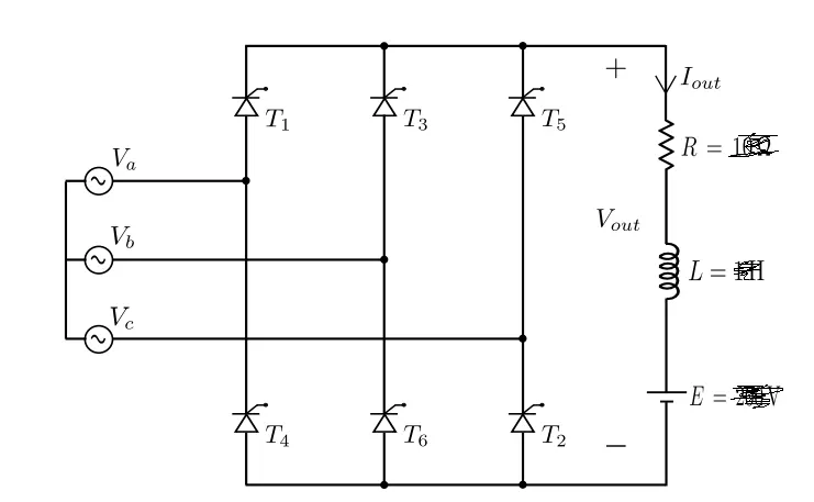
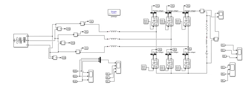
Circuit diagram:-
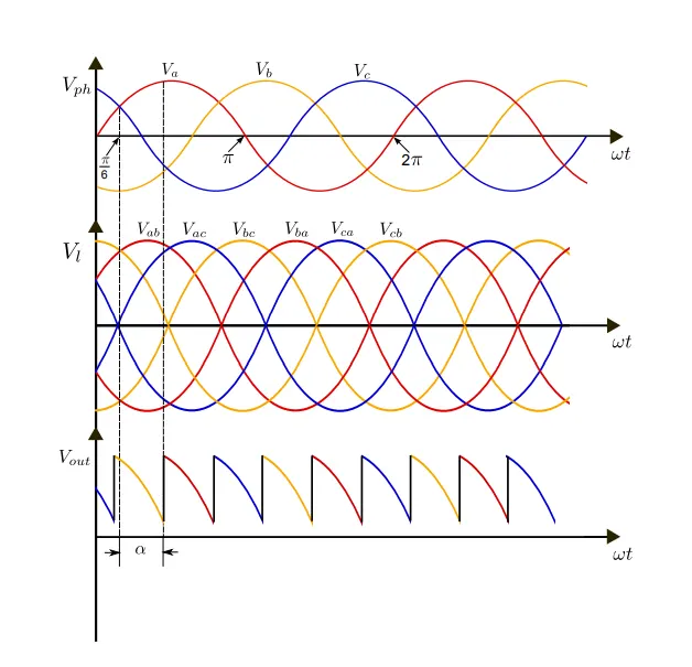
waveform
For a 3 - phase full wave controlled rectifier shown in Fig. 1, the output voltage is alwaysdifference between two phase voltages. At any instant of time two thyristors of differentlegs conduct. Let us consider the instant at which T1 and T6 conduct. Solving KVL, the output voltage Vout is equal to the difference between Va and Vb. Similarly this appliesfor every other combination of conduction of thyristors. The output waveform forcontinuous conduction is shown in Fig
Simulink model:-
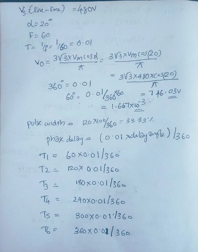
Calculation:-
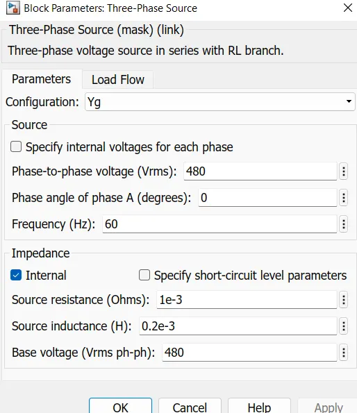
Ac source
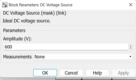
R,L,Vdc
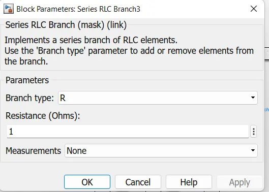
R,L,Vdc
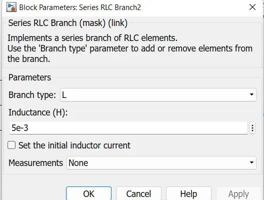
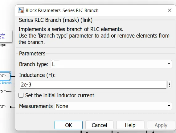
Ls
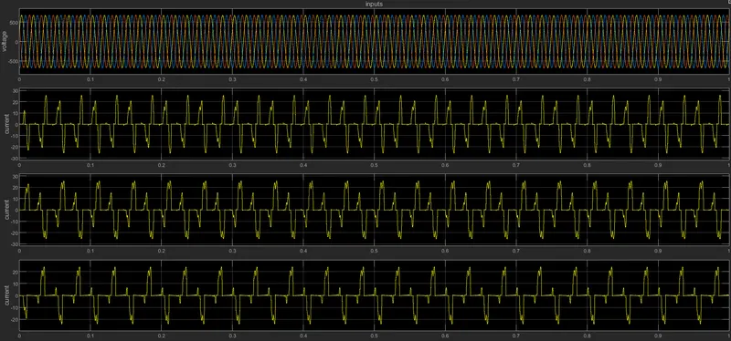
Results:-
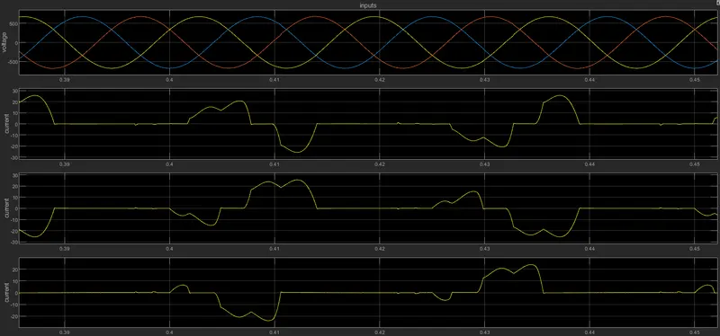
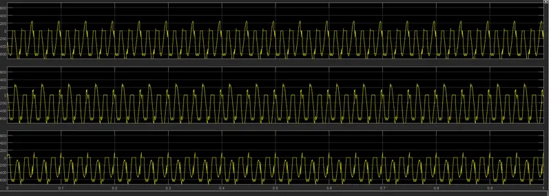
input voltage and current
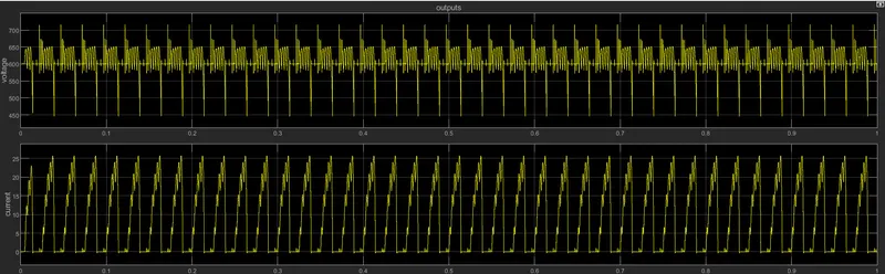
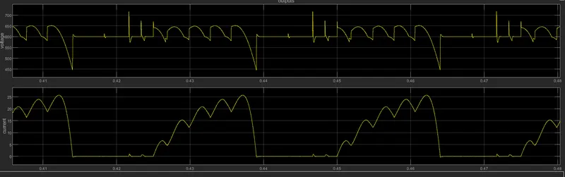
output voltage and current
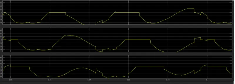
Thyristor voltages
t1,t2,t3
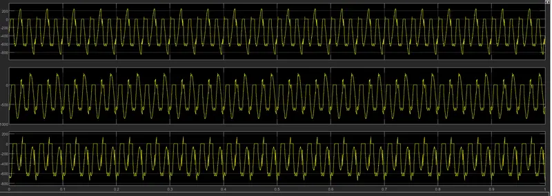
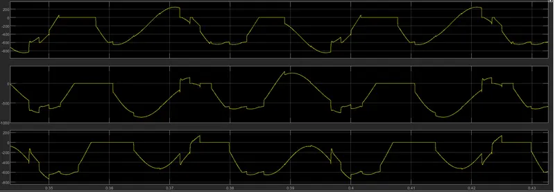
t4,t5,t6
FFT analysis
input analysis
input1
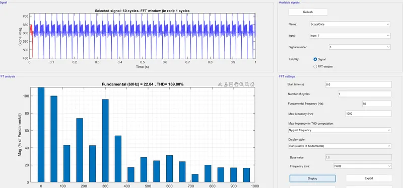
here ,
fundamental 60hz=22.84
and THD=169.80
LIST
LIST
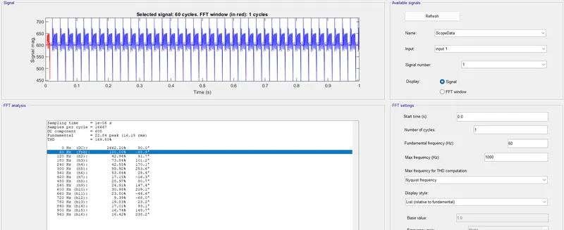
60HZ= -69.5 DEGREE
INPUT2
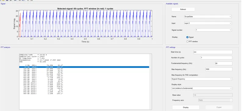
for 60hz
232.0 degree
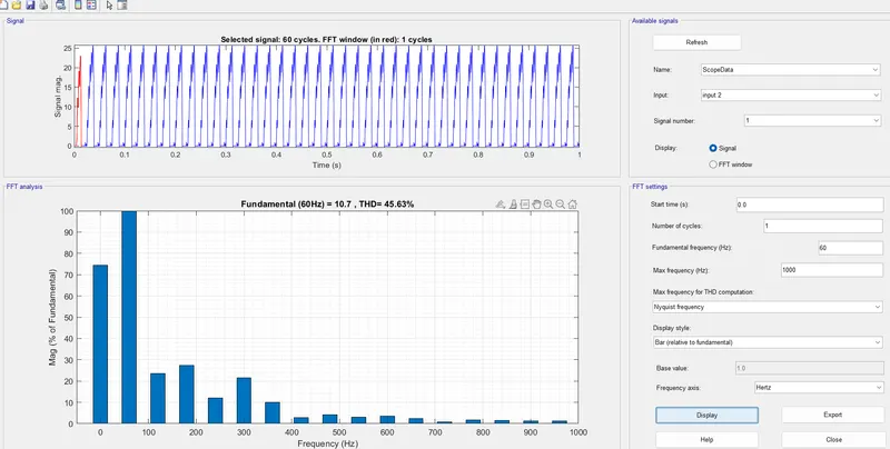
fundamental 60hz=10.7
and THD =45.63