Project 1
WIRING HARNESS ROUTING OF ENGINE USING CATIA V5
OBJECTIVE: The objectives of this challenge are as given below,
- To Define the mechanical components electrically and prepare the catalogue for the same.
- To Provide proper routing of bundle without and interference and also provide support parts like clips and clamps.
- To Prepare a report with all the required images required for the challenges.
- To Attach all the file required for e the challennge.
DESIGN METHODOLOGY
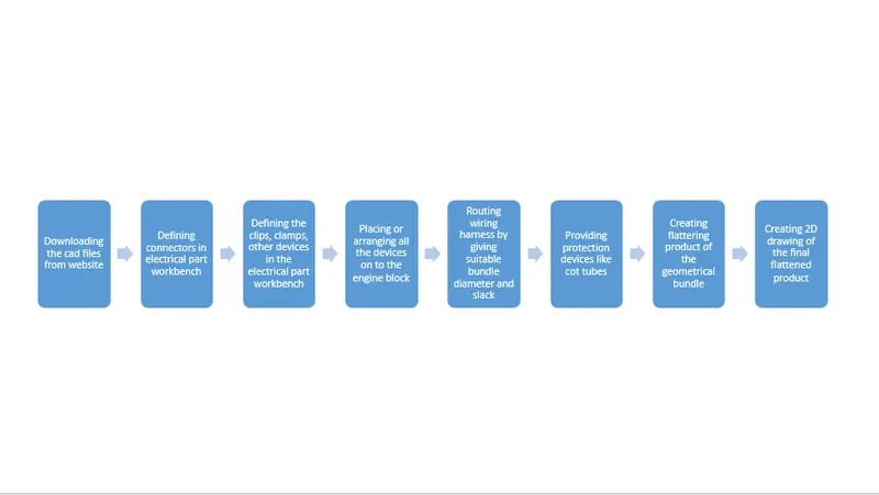
The design methodology or design approach which is used for this challenge is explained or given in the below flow chart,
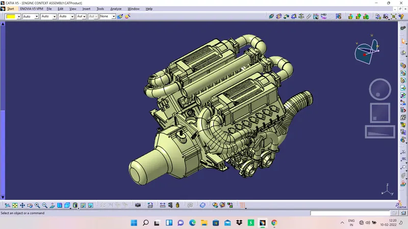
1. The given engine block is shown in the below picture,
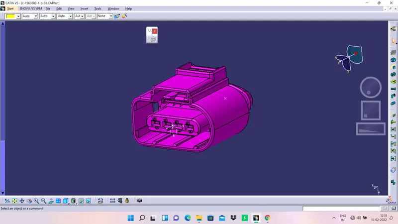
2. Now let us define the connectors by creating points and axis system on the connector connecting side in the part workbench and to define them electrically in the electrical part design workbench, below are the images of different conenctors used in this project,
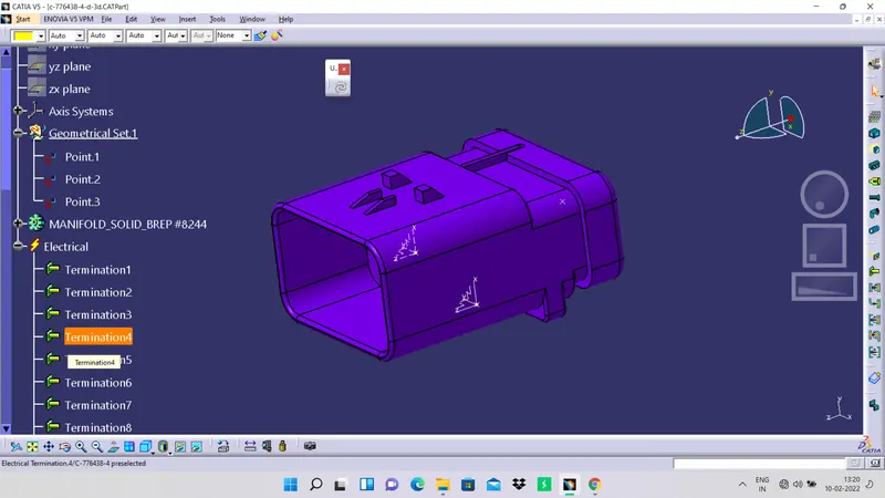
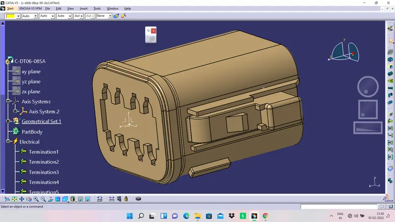
3. Now let us define the cavities and clamps by creating points and axis system on the connector connecting side in the part workbench and to define them electrically in the electrical part design workbench, below are the images of different conenctors used in this project,
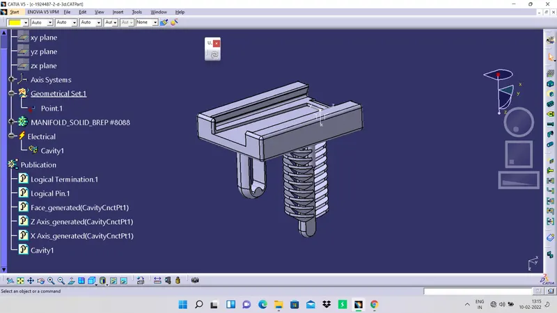
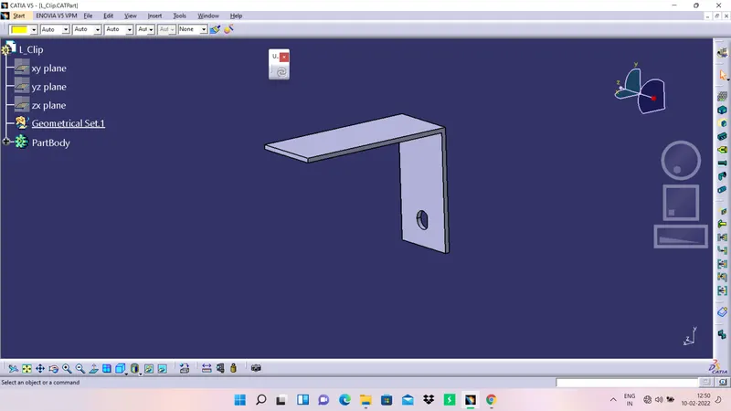
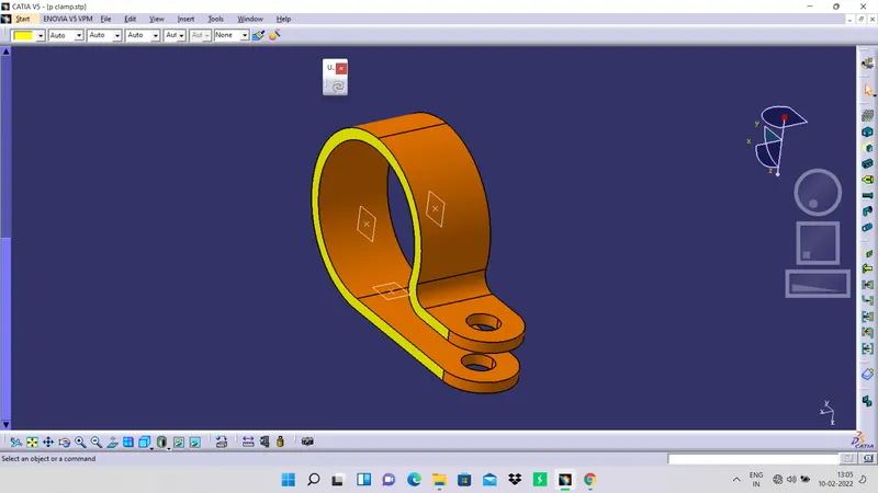
4. Position the conectors in the place of dummy connectors which are given on the engine and place them correctly relative to the dummy connectors. The below image shows the arrangment of connector on one side.
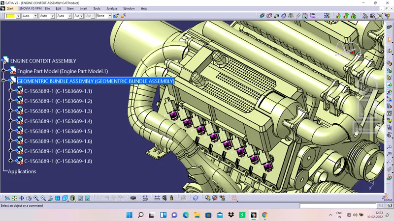
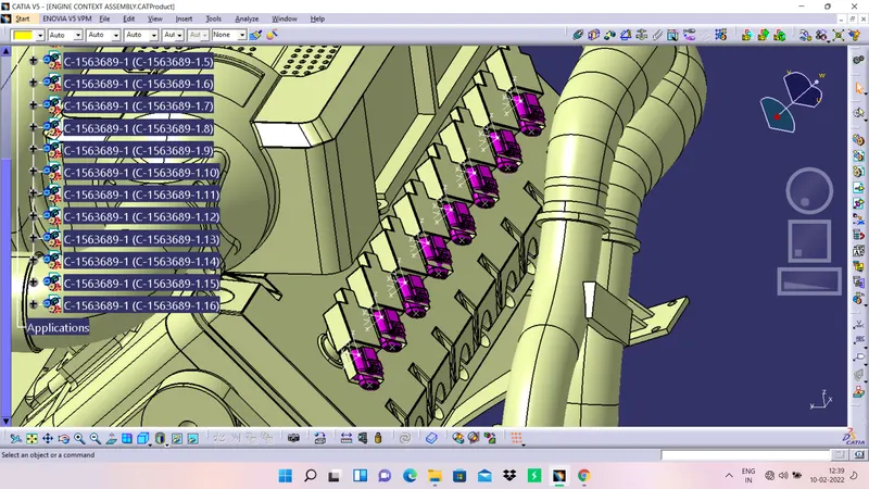
5. In a similar fashion arrange the same connector on the other side and below is the image of the same,
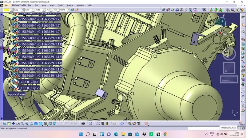
6. Arrange the L clip in the slots given in the engine block and make sure the arrangment is proper,
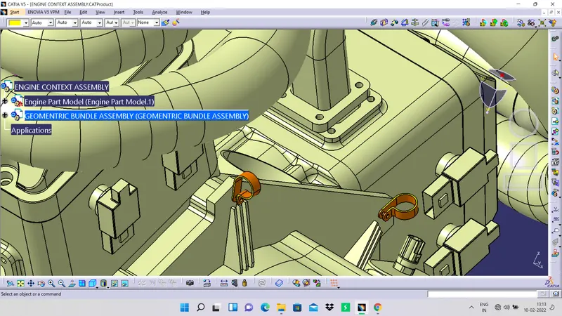
7. Now arrange the p clamp and my arrangment of p clamp is shown in below figure,
8. Now arrange the connector and respective cavity on the L clamp and the below image shows the same,

9. Now arrange the sensor connectors to the engine block in place of dummy connectors which are given on the engine connector,
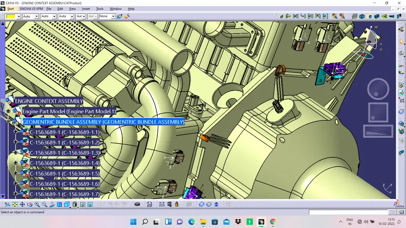
10. Start routing the devices in the electrical harness assembly and give the diameter of the bundle as per requirements and provide slack if required.
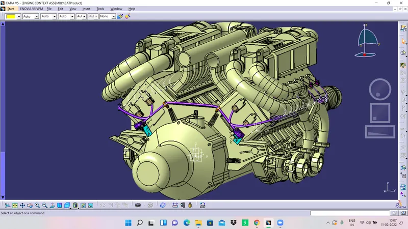
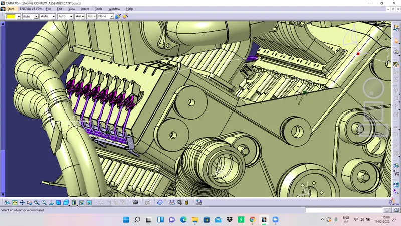
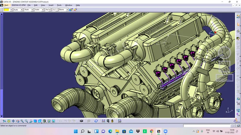
11. Then add protective covering to the bundles such as cot tubes and give colours to differentiate different types of cot tubes if required.
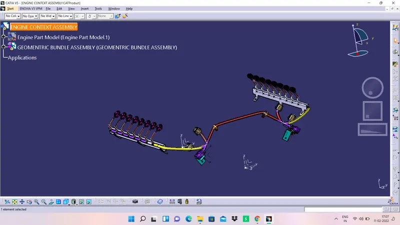
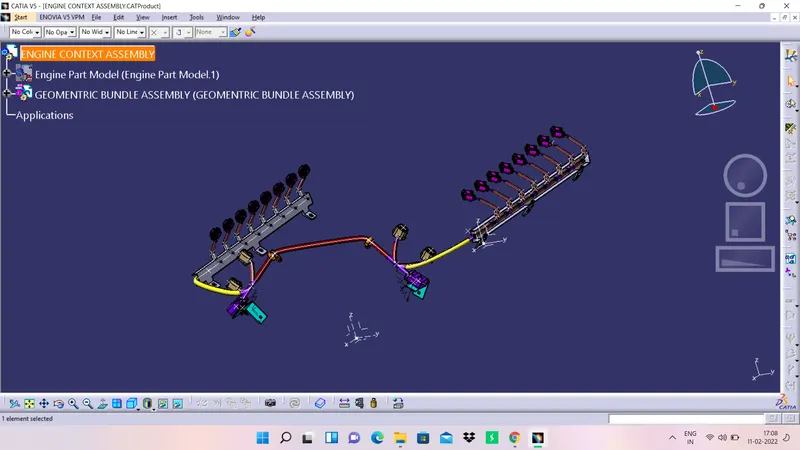
12. Create a flattening product for the geomentrical bundle and flatten in the Electrical Harness Flattening workbench.
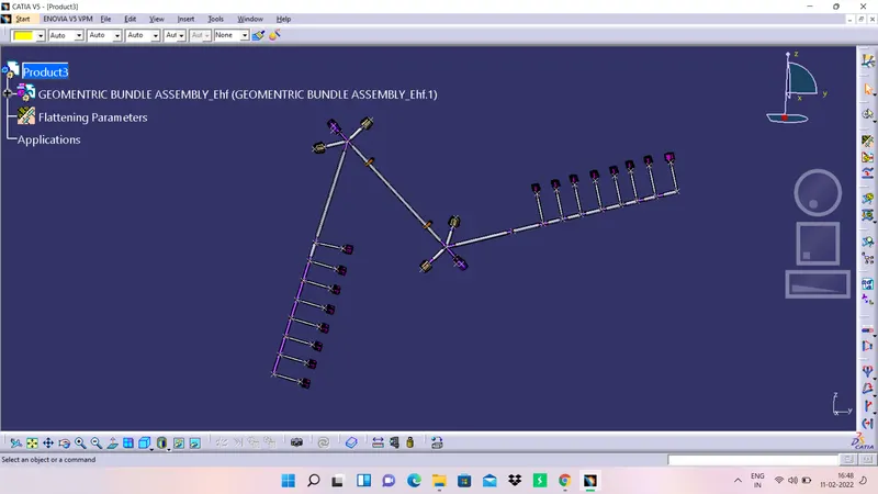
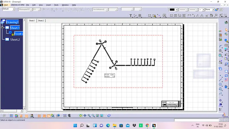
13. Finally create a 2d drawing in the drawing workbench and create bill of materials table on the sheet along with frame and title block.
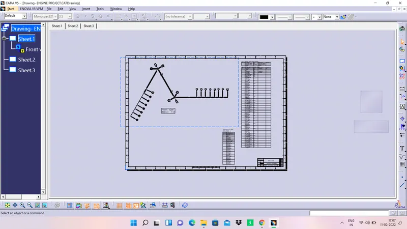
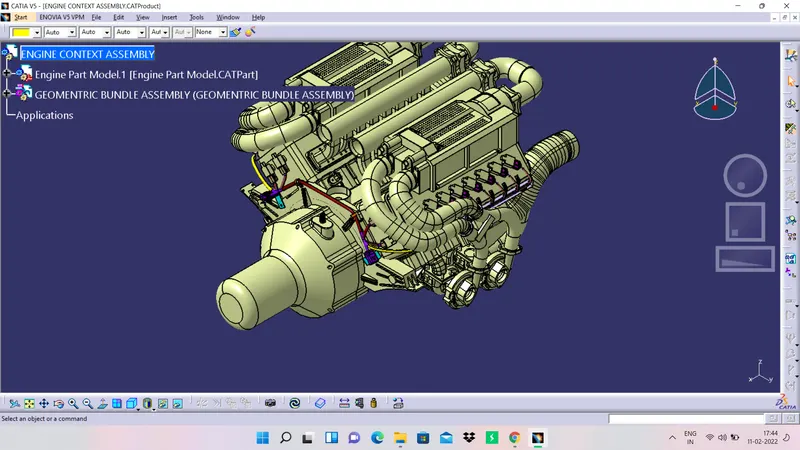
Finally let is see the different views of engine with harness routing,
ISOMETRIC VIEW
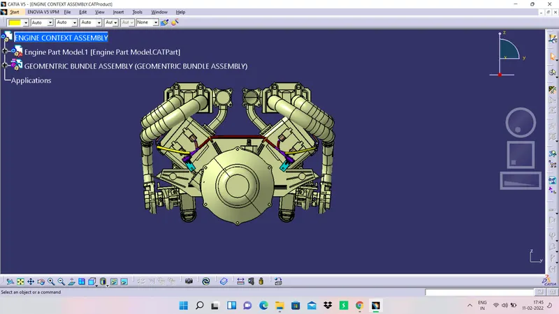
FRONT VIEW
BACK VIEW
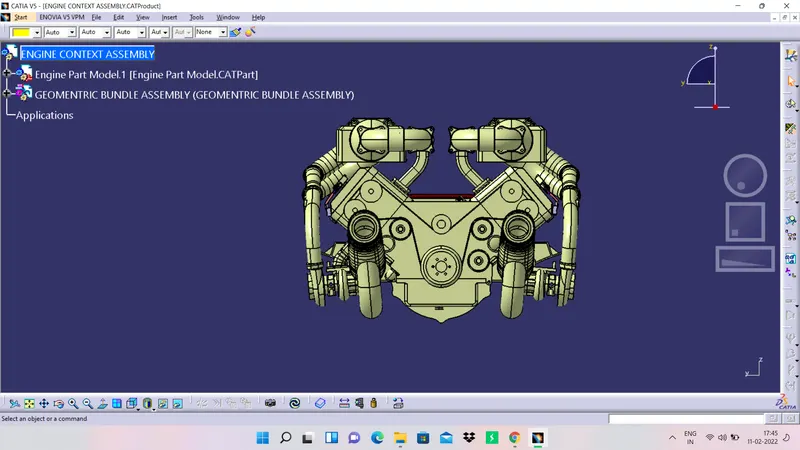
LEFT SIDE VIEW
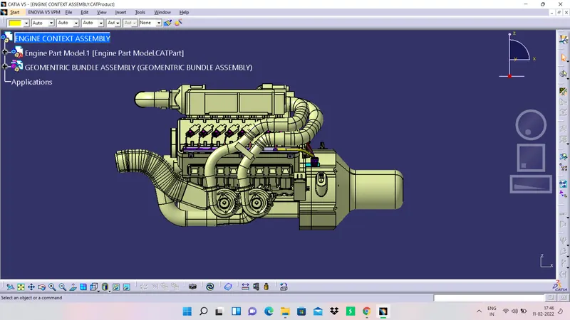
RIGHT SIDE VIEW
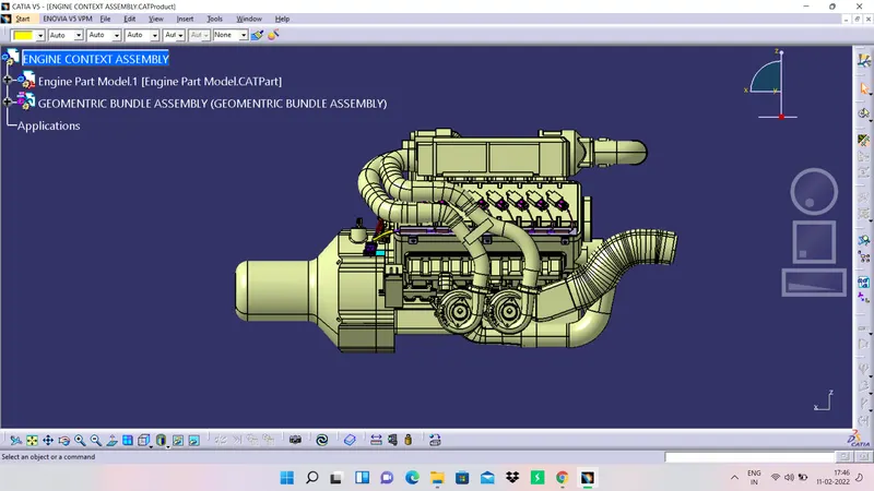
TOP VIEW
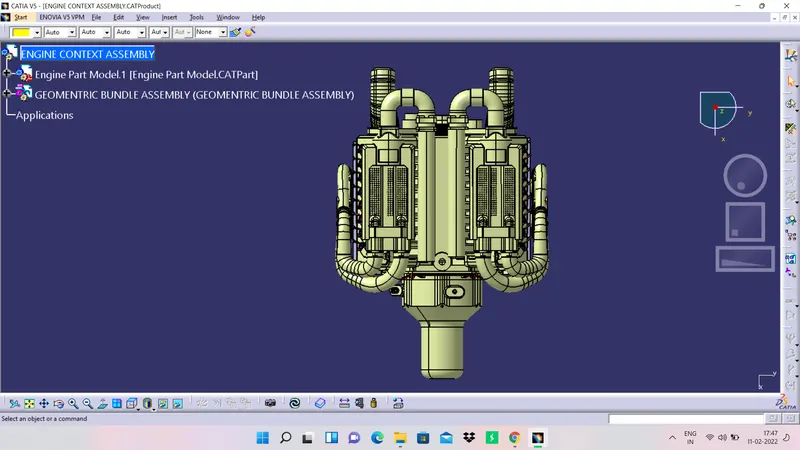
BOTTOM VIEW
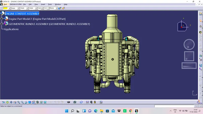
NOTE:
- The cot tubes in yellow colour are of silica material which is more resistive to heat when compared with other cot tubes and it is of 12 mm diameter.
- The cot tubes in brown colour are normal cot tubes which are of 12 mm diameter.
- The cot tubes in pinkish red colour are also normal cot tubes which are of 7 mm in diameter.
CONCLUSION
Thus, the objectives of this challenge are achieved and a detailed report has been prepared. A zipped folder which contains the cad files is attached to the challenge successfully.