Project 1
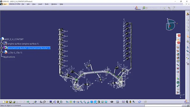
Step 1: Creating Context Assembly
- A Context Assembly for Engine Harness has created which will work as the main assembly as shown in above figure.
- A Context Assembly will contain Engine Assembly data for Bugatti V16 Engine and Engine Harness Geometrical Bundle Assembly.
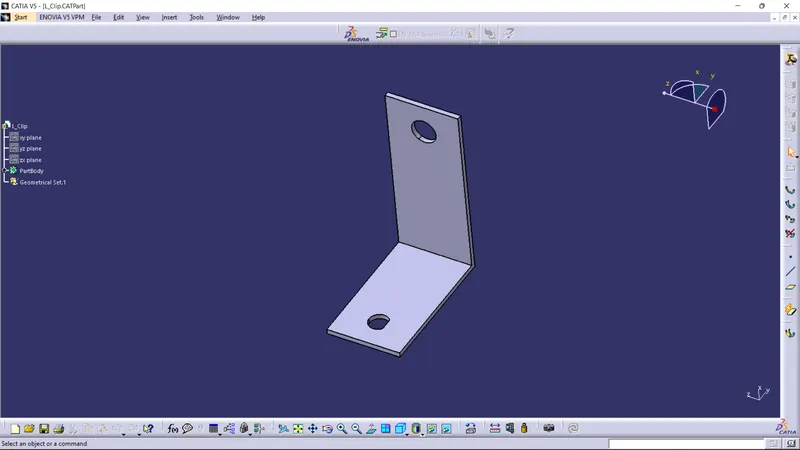
- If any sheet metal bracket will require then they are added in the context assembly.
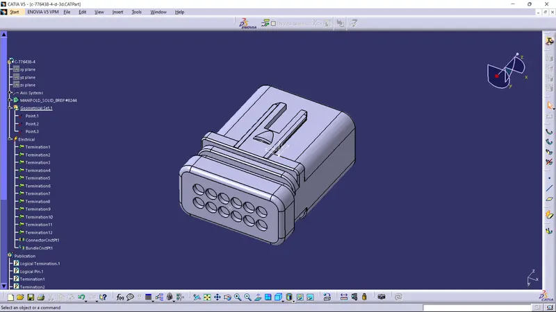
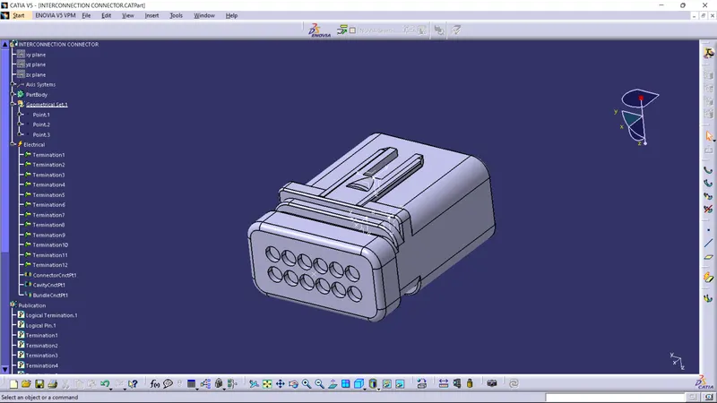
12POLE CONNECTOR
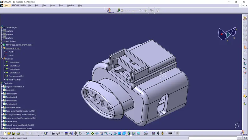
4 POLE CONNECTOR
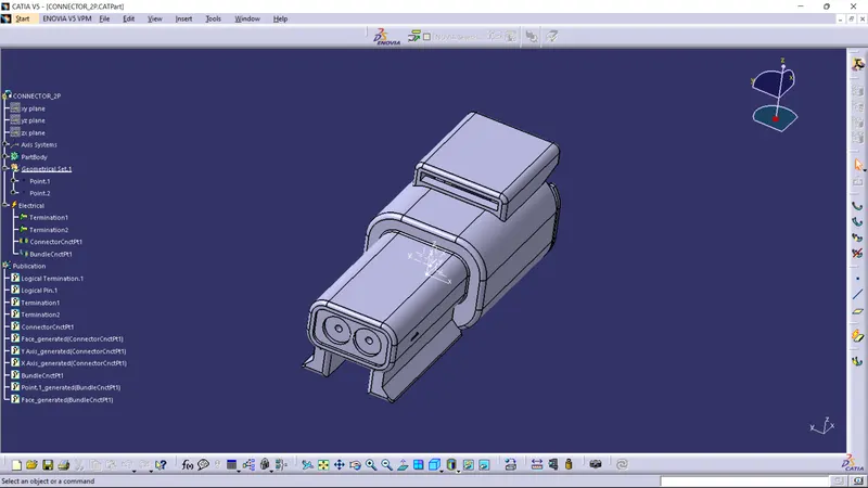
2 POLE CONNECTOR
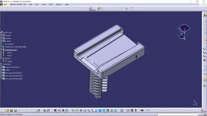
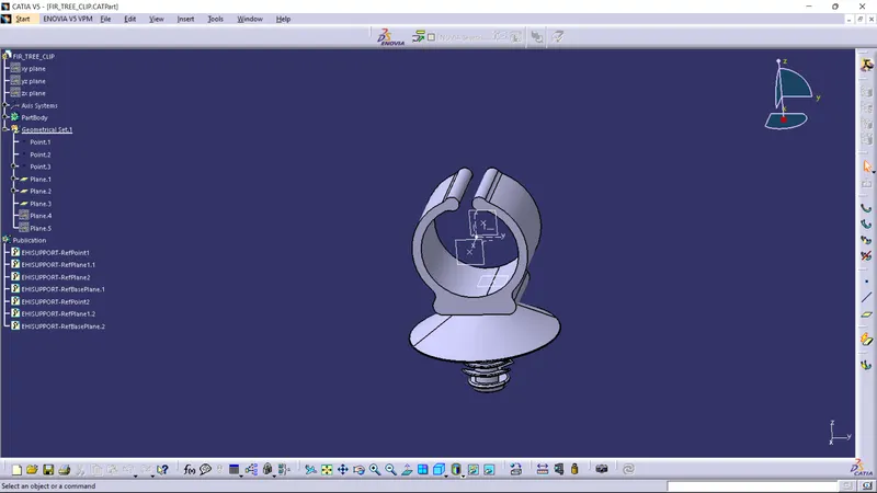
FIR TREE CLIP
L_CLIP
Step 2: To define 4-pole connector electrically
We have to define all the connector that is 2 pole, 3pole, 4 pole and 12 pole interconnection connector as an electrical part by define as connector connection point and bundle connection point.
Also define the clip and channels that is needed as an electrical part.
Step 3: Adding connectors to the all 16 fuel injector sensors and 4 cam-shaft sensors
In this step, we are placing connectors to fuel injector sensors and cam-shaft sensors. So we will require total 20 connectors which have to be added in the Engine Harness Geometrical Bundle Assembly. We have to use manipulation tools along with compass, snap and smart move features to locate all the 20 connectors at their desired locations.
Step 4: Adding sheet metal bracket
Step 5: Mounting the interconnection connector on the sheet metal bracket and mounting the p-clamps for wire harness
Step 6: Mounting of a plastic guiding channel
Step 7: Bundle routing from Interconnection connector to 3 P-clamps
Step 7: Bundle routing from Interconnection connector to 3 P-clamps
Step 9: Routing to the plastic guiding channel
Step 10: Adding branch points to bundle segment inside the guiding channel
Step 11: Adding protective coverings and guiding channels top shell to harness bundle
Step 12: Checking bundle continuity