Project 1
PROJECT NUMBER :- 01
SUBMITED BY :- ABHISHEK VERMA
01. Design a multi-storey Residential Building located in Bangalore using STAAD Pro Connect Edition.
The specification must be as follows :-
|
Building floors |
G + 6 + R |
|
Plan dimension |
B = 25m , L = 16m |
|
Storey Height |
h = 3.5m |
|
Soil |
Hard soil |
|
Use |
Residential Purpose |
|
Safe Bearing Capacity |
180 kN/m2 |
|
Maximum slab thickness |
150mm |
Assume suitable sections for structural elements. Follow IS456, IS1893 and IS 875
AIM :-
- Design a multi-storey Residential Building located in Bangalore using STAAD Pro Connect Edition
INTRODUCTION :-
- From model generation, analysis and design to visualization and result verification, STAAD Pro is the professional’s choice for steel, concrete, timber, aluminum and cold-formed steel design of low and high-rise buildings, culverts, petrochemical plants, tunnels, bridges, piles and much more.
- It is one of the effective software which is used for the purpose of analysis and design of structure by the structural engineers. Our project is aimed to complete with the help of STAAD Pro. STADD Pro gives more precise and accurate results than manual techniques.
- Advanced structural analysis may examine dynamic response, stability and non-linear behavior. Few standard problems also have been solved to show how “STAAD. Pro” can be used in different cases. These typical problems have been solved using basic concept of loading, analysis, condition as per IS code 456:2000. These basic techniques may be found useful for further analysis of problems.
Features :-
- Analysis and design tool
- GUI based modeling
- Input file/Output file
- Results as per Indian standards
STEPS INVOLVED :-
The software follows the matrix stiffness principle in analyzing the structure. The steps for analyzing a structure using STAAD Pro are given below.
- Generation of nodes
- Modeling of the structure
- Restraints
- Assigning of the structure members
- Application of loads
- Run analysis
GENERATION OF NODE :-
The nodes are generated based on the dimensions of the building.
The plan dimension B=25m, L=16m and height=3.5m.
Then the grid spacing is given on the STAAD Pro window.
The software automatically generates a grid with a specified window.
MODELLING OF THE STRUCTURE :-
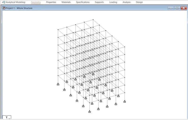
After the nodes are created they are jointed with line elements in fig. Based on the dimension of the building the nodes are joined. Unwanted nodes could be deleted.
RESTRAINTS :-
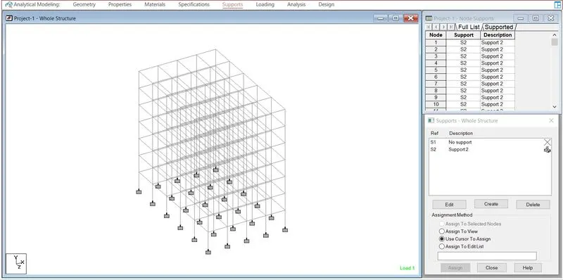
After the structure has been modeled the restraints has to given.
ASSIGNING OF THE STRUCTURAL ELEMENTS :-
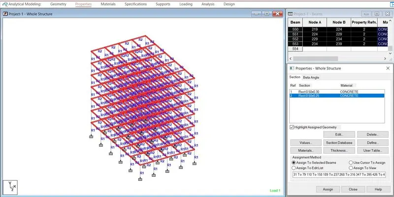
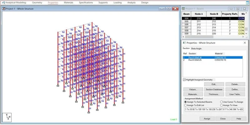
The software has the facility to assign the structural elements. The line elements have to be assigned as beam, column and plates and appropriate dimension are given.
ASSIGNING OF THE BEAM :-
Beams are designed for flexure, shear, and torsion. If required the effect of the axial force may be taken into consideration. For all these forces, all active beam loadings are pre-scanned to identify the critical load cases at different sections of the beam.
ASSIGNING OF THE COLUMN :-
Columns are designed for axial forces and biaxial moments per IS 456:2000. All major criteria for selecting longitudinal and transverse reinforcement as stipulated by IS:456 have been taken care of in the column design of STAAD.
ASSIGNING OF LOADS :-
There are the various loads acting on a structure.
- Self-weight
- Floor load
- Wind load
- Load combination
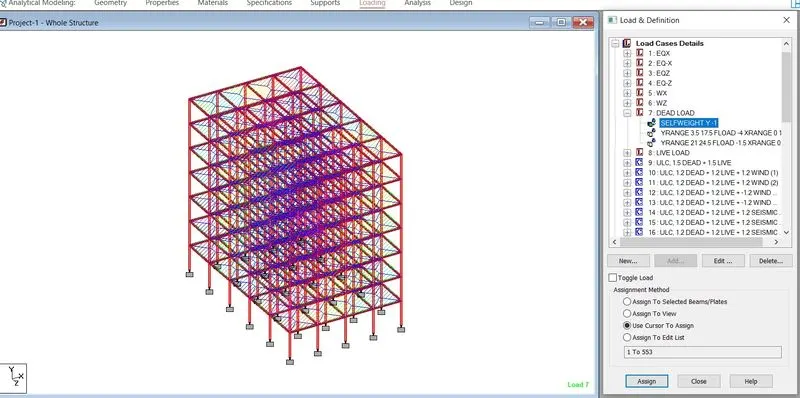
Selfweight :-
The self weight of the structure can be generated bySTAAD PRO itself with the self weight command in the load case column.
Floorload :-
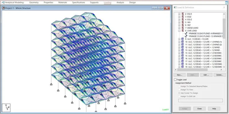
Floor load from the slab can also be generated by STAAD PRO by specifying thickness and the load on the floor per sq m.
The live loads were generated in a similar manner as done in the earlier case for the dead load on each floor. This may be done from the member load button from the load case column.
Windload :-
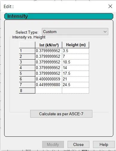
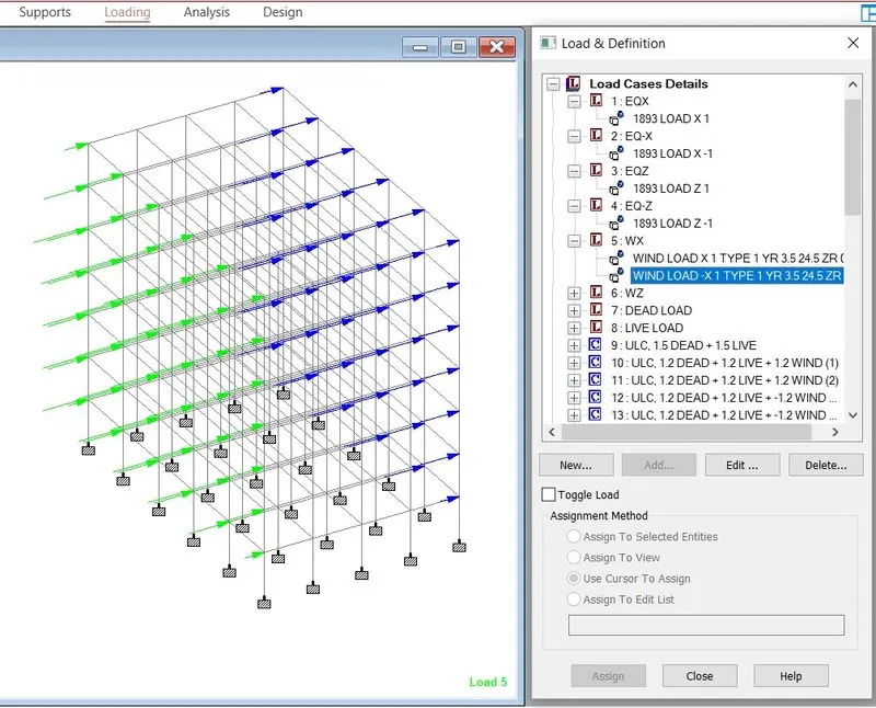
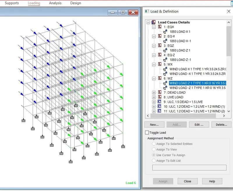
The wind load values were generated by the software itself in accordance with IS 875. Under the defined load category, the definition of wind load was supplied. The wind intensities at various heights were calculated manually and feed to the software. Based on those values it generates the wind load on different floors.
Seismic load :-
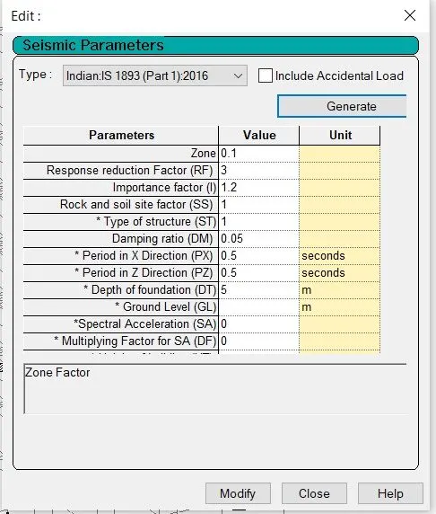
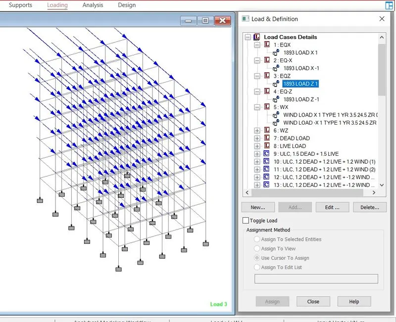
The seismic load values were calculated as per IS1893-2002. STAAD Pro has a seismic load generator in accordance with the IS code mentioned.
The seismic load generator can be used to generate lateral load in the X and Z direction only. Y direction is the direction of gravity loads. This facility has not been developed for case where the Z axis is set to be the vertical direction using the “SET Z UP” command.

Load combination :-
The structure has been analyzed for load combination considering all previous loads in the proper ratio. In the first case of a combination of self-weight, dead load, live load, and wind load were taken into consideration. In the second combination case instead of wind load seismic load was taken into consideration
Run Analysis :-
When the last step, run analysis is executed it shows “Analysis complete”, which indicates the termination of the analysis process. Based on the analysis result, the building is designed in accordance with the provisions mentioned in the Indian Standard Codes.
Design of G+6+Roof Multi-Storey Residential Building located in Banglore using STADD.Pro
The structure was designed for concrete in accordance with IS code. The parameters such as clear cover, Fy, Fc, etc were specified. The window shown below is the input window for the design purpose. Then it has to be specified which member is to be designed as beam and which members are to be designed s columns.
Design Parameters :-
- CLEAR COVER FOR BEAM- 30mm
- CLEAR COVER FOR COLUMN- 50mm
- FC- 40000 N/mm2
- FY MAIN- 500000 N/mm2
- FY SEC- 500000 N/mm2
- MAX MAIN- 32mm
- MAX SEC- 20mm
- MIN MAIN- 16mm
- MIN SEC- 8mm
Primary load cases :-
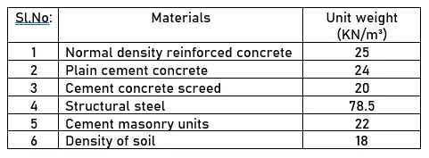
Dead load, Live load & Superimposed dead load.
Dead load :- Weight of the structure, it remains constant.
Superimposed DL :- It covers floor finish & service load, may vary for each floor & material.
Live load :- Residential building locted in Banglore.
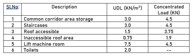
Prepare a Design Basis Report for the project :-
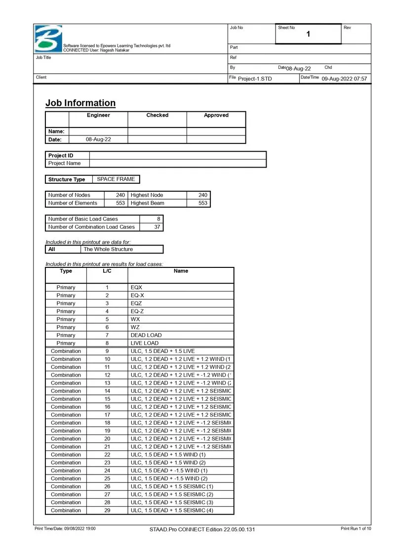
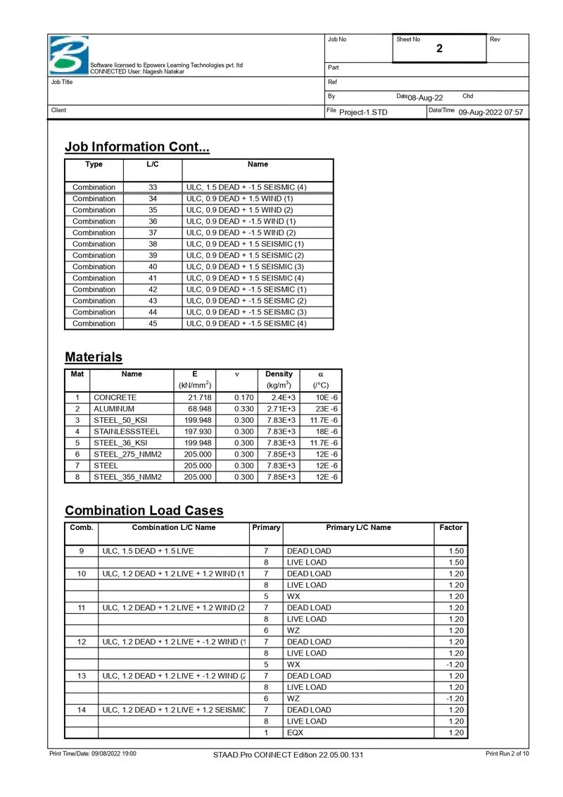
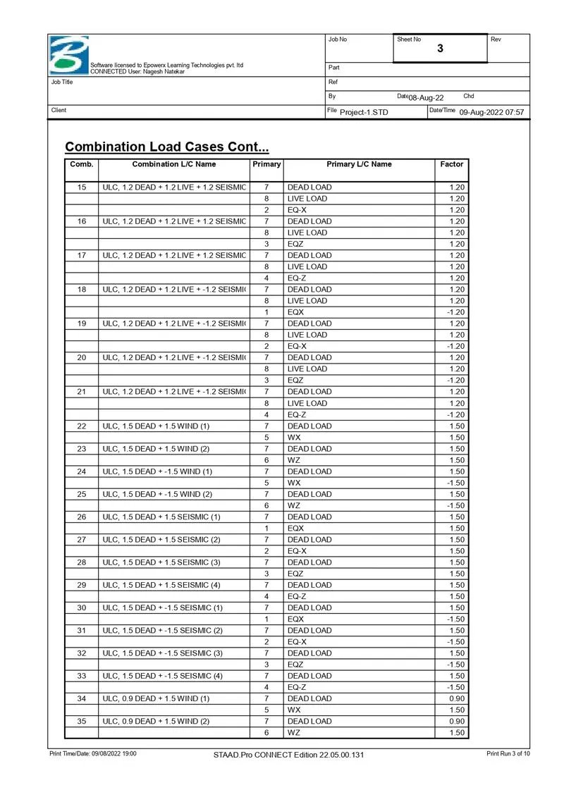
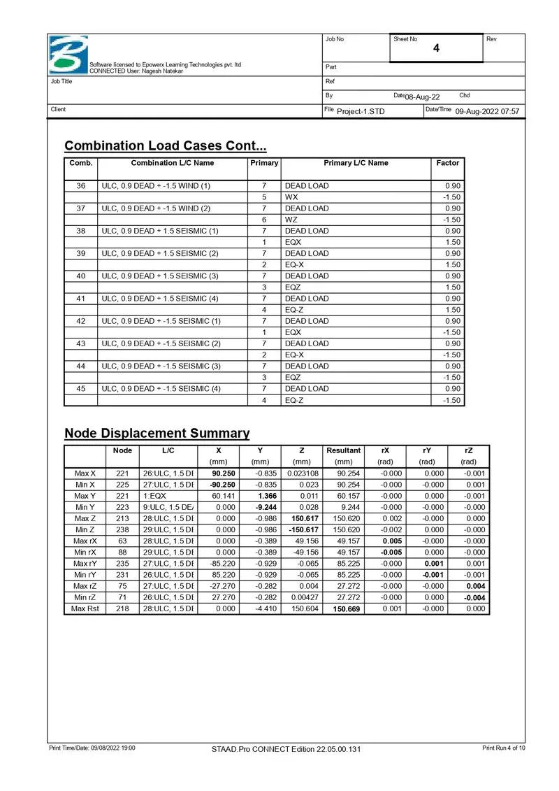
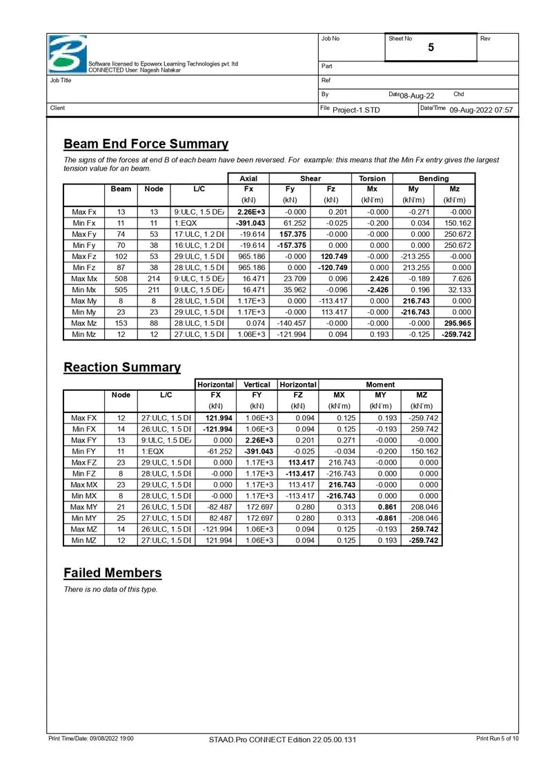
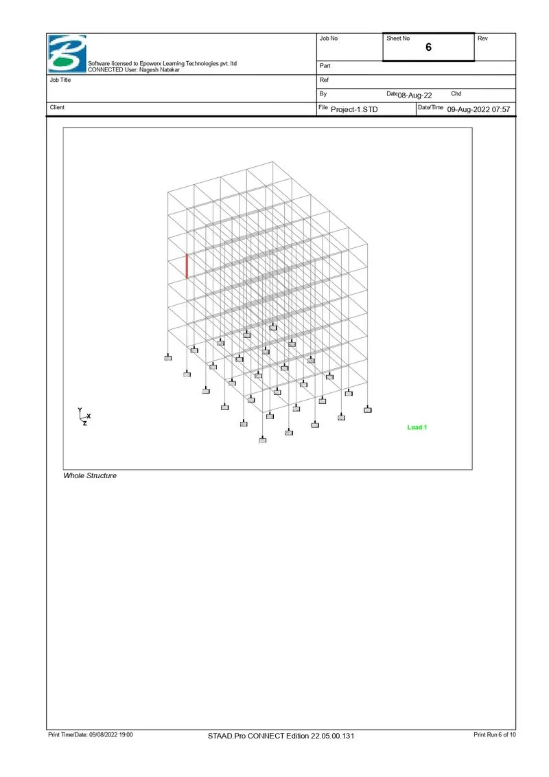
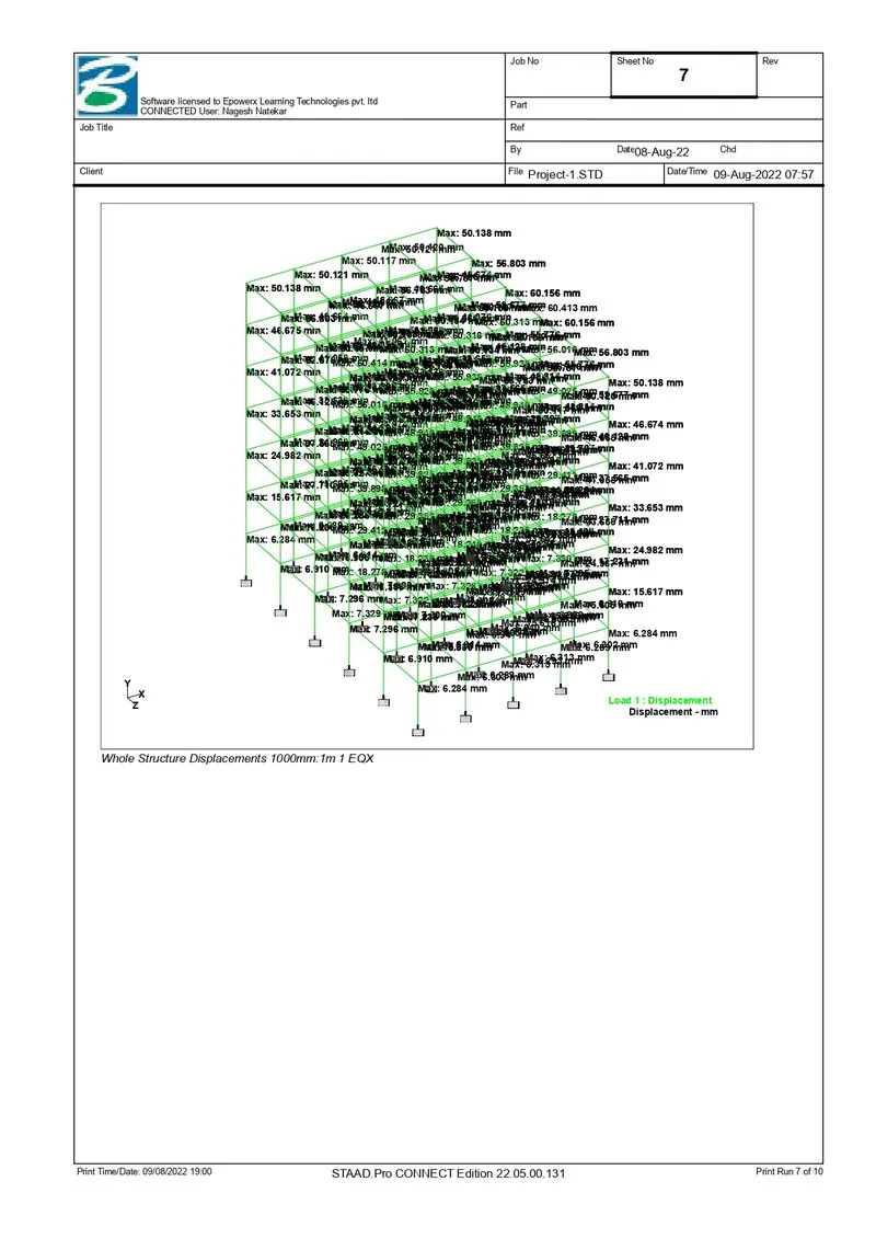
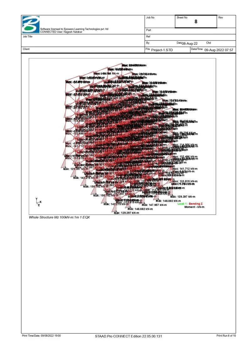
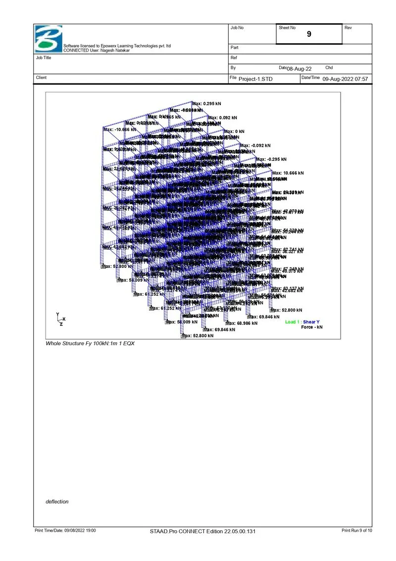
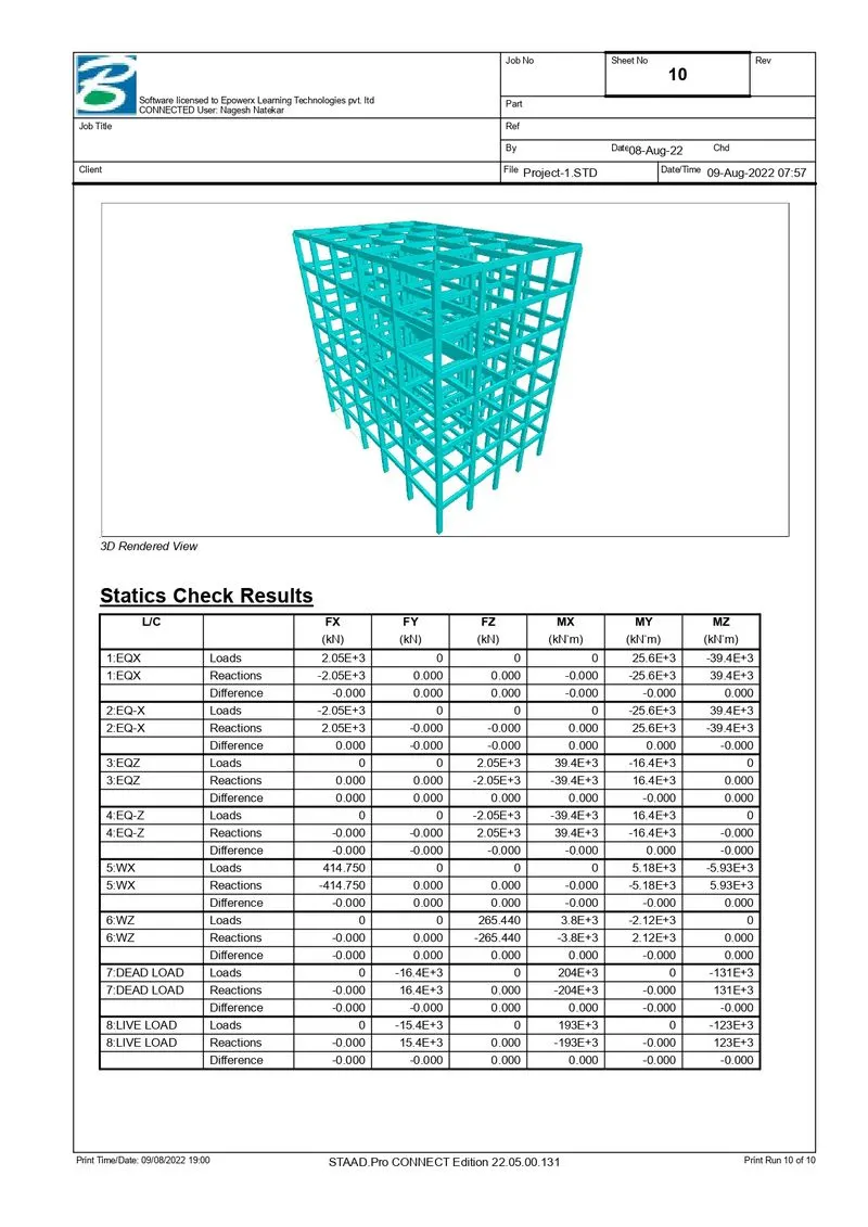
Column Design from Stadd pro :-
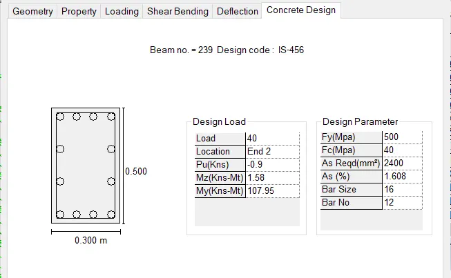
Beam Design from Stadd pro :-
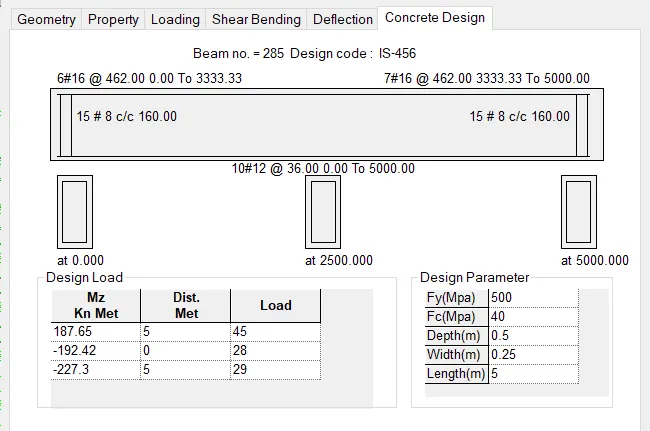
Calculate the Dead load and Live load for the above building with reference to IS standards
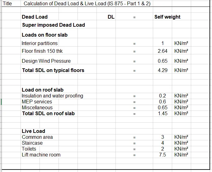
Calculate the wind Load for the given building
a. Building Dimension : L=16m, B=25m, 24.5m height
b. Building usage : Residential Building
c. Location : Banglore
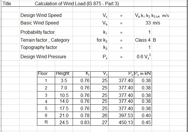
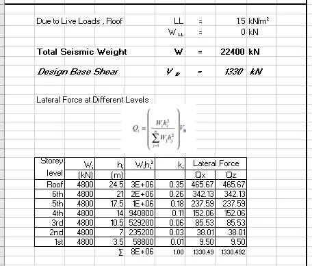
EQL load calculations as per IS 875 standards:
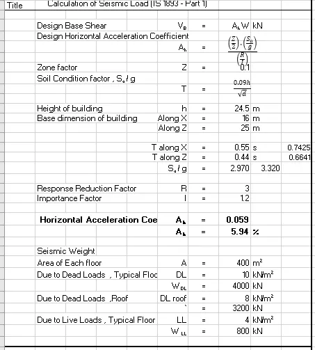
Design slab element using MS – Excel
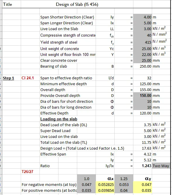
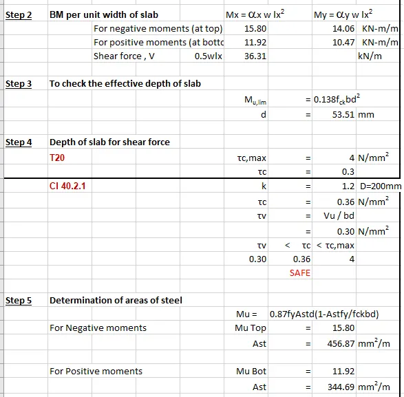
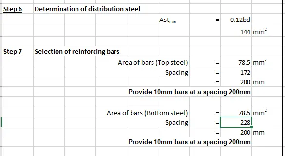
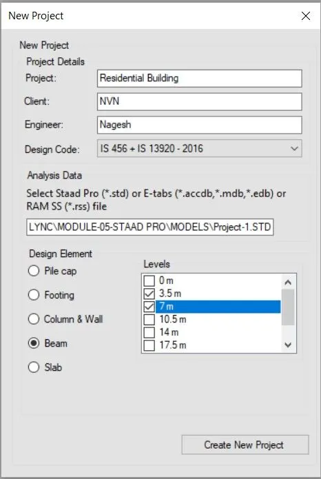
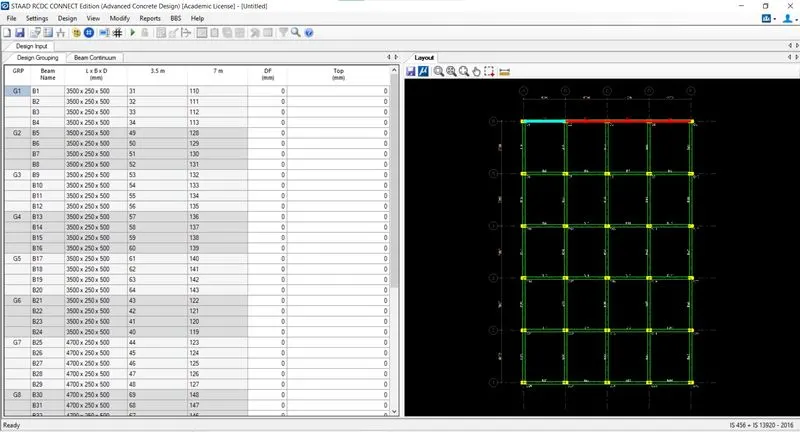
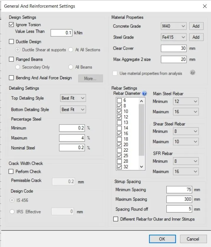
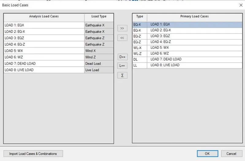
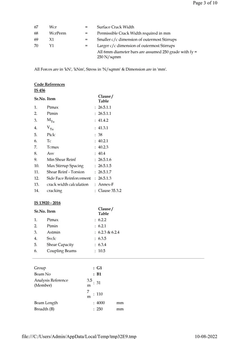
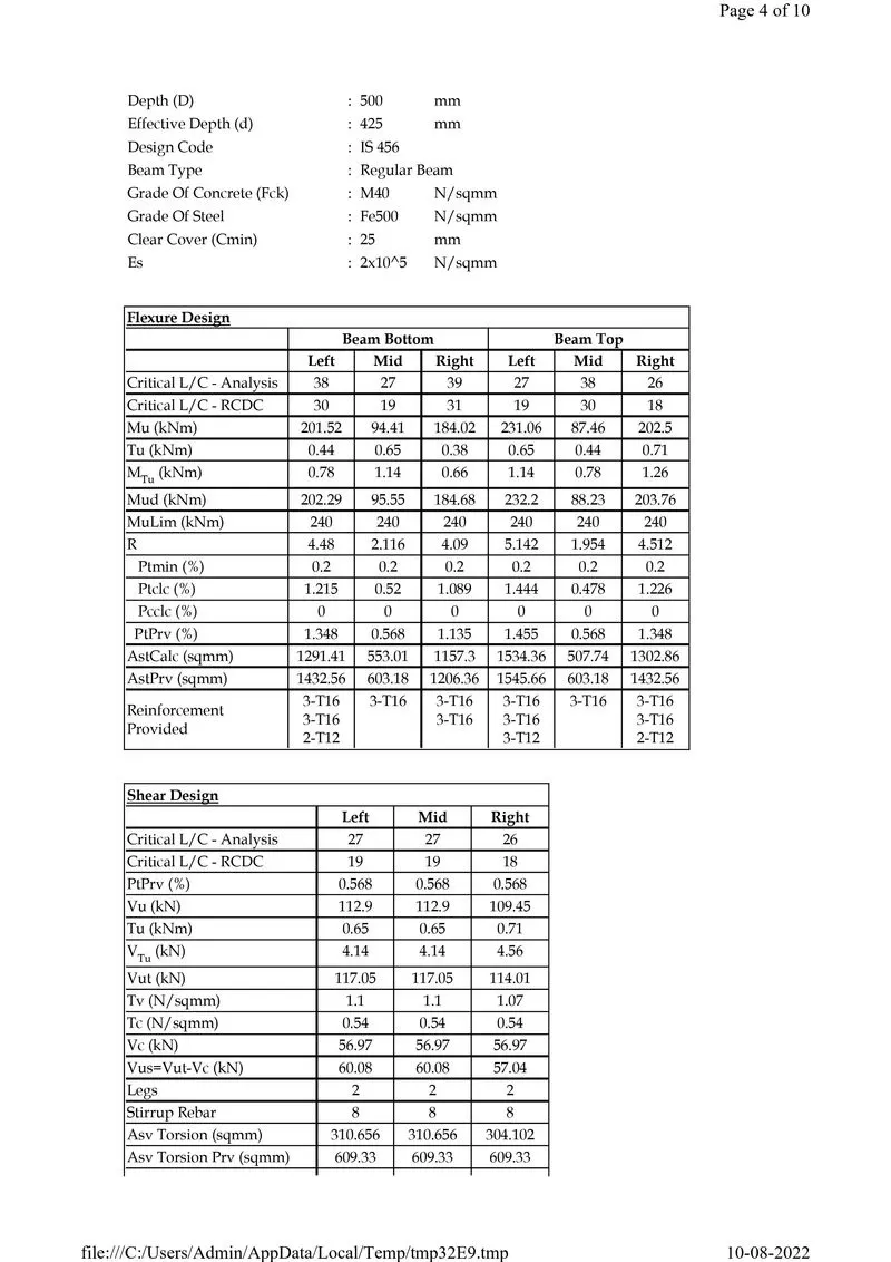
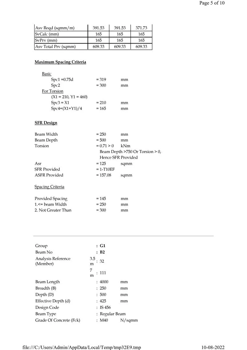
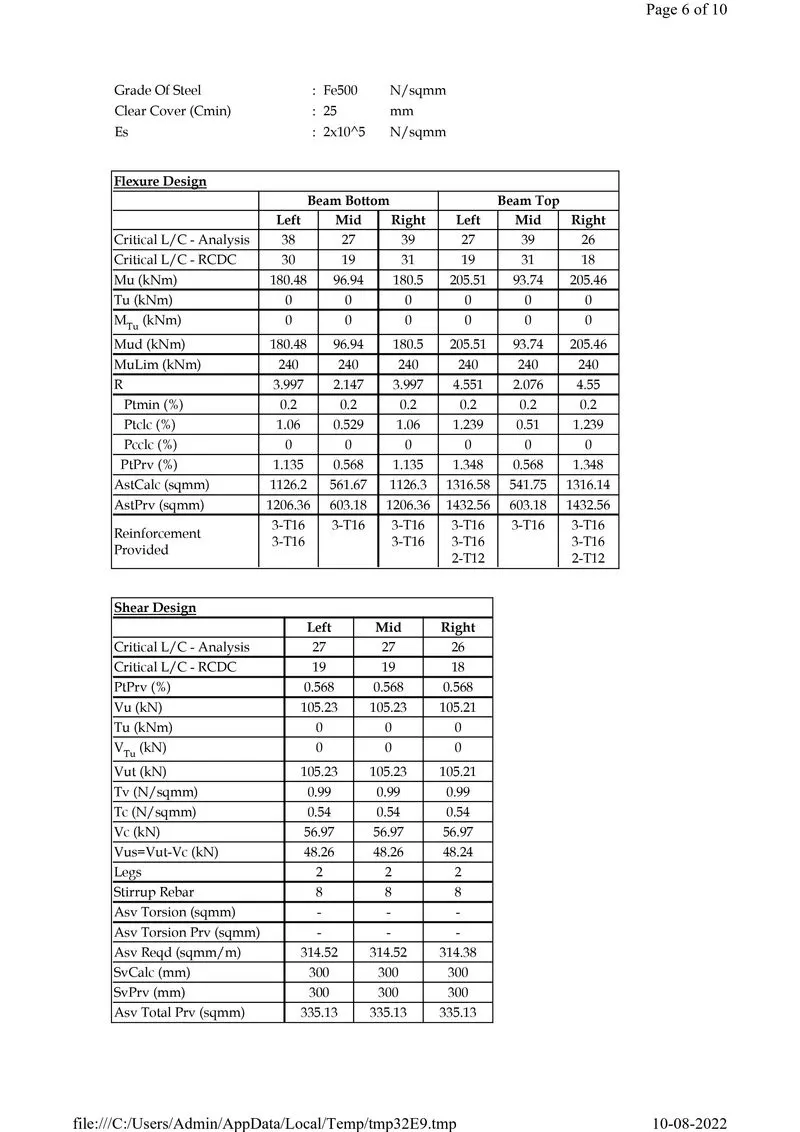
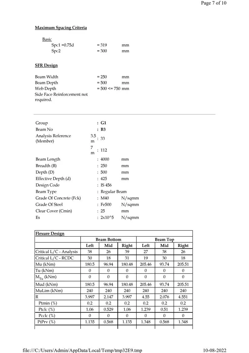
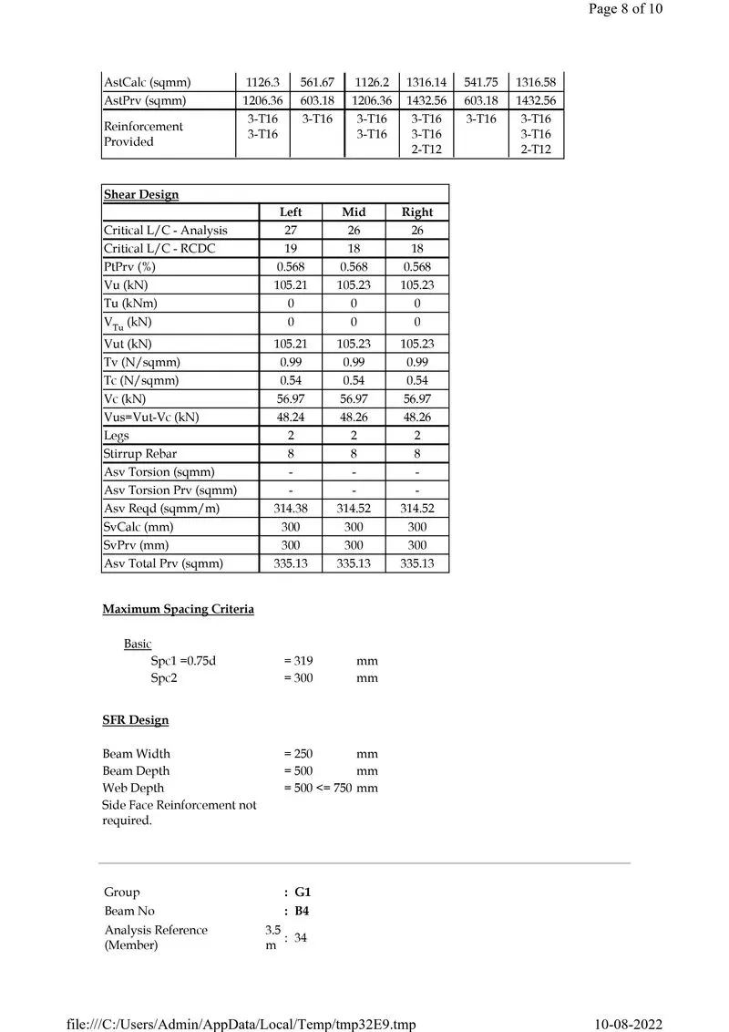
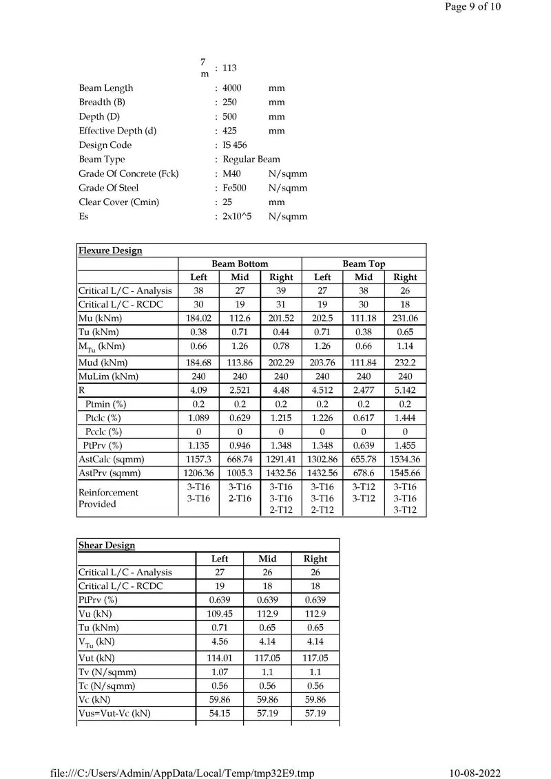
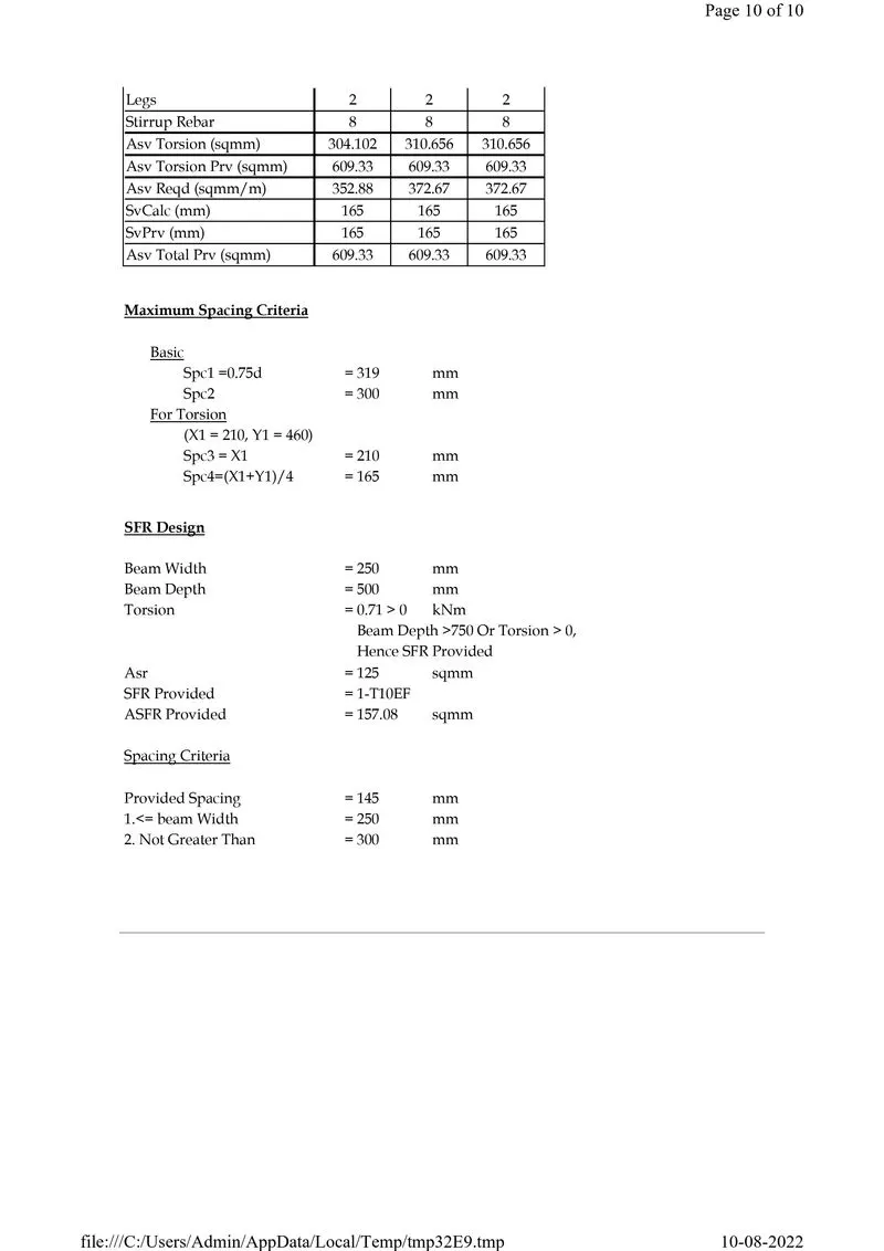
Design beam and column element using STAAD RCDC. Attach the design calculation report :-
BEAM STAAD RCDC :-
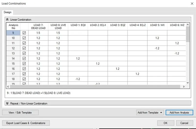
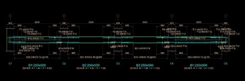
Design calculation report :-
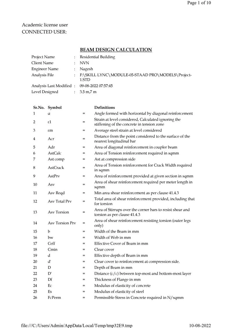
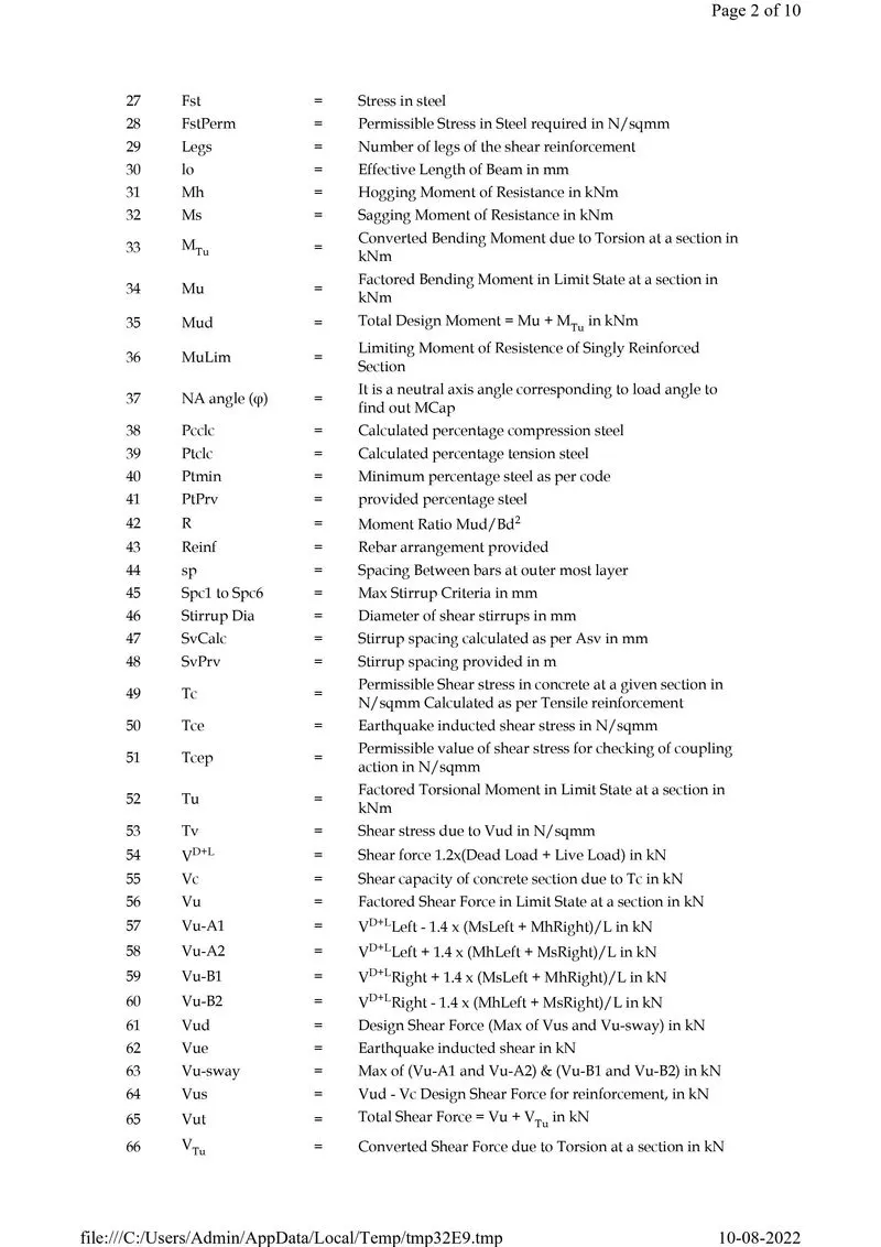
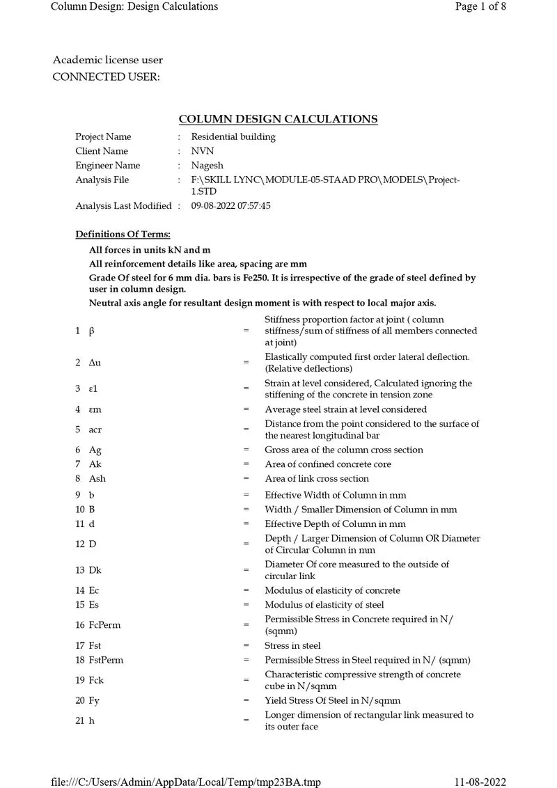
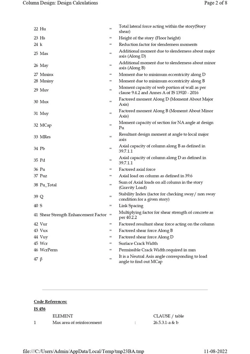
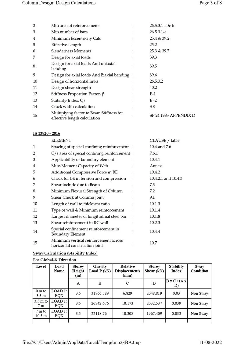
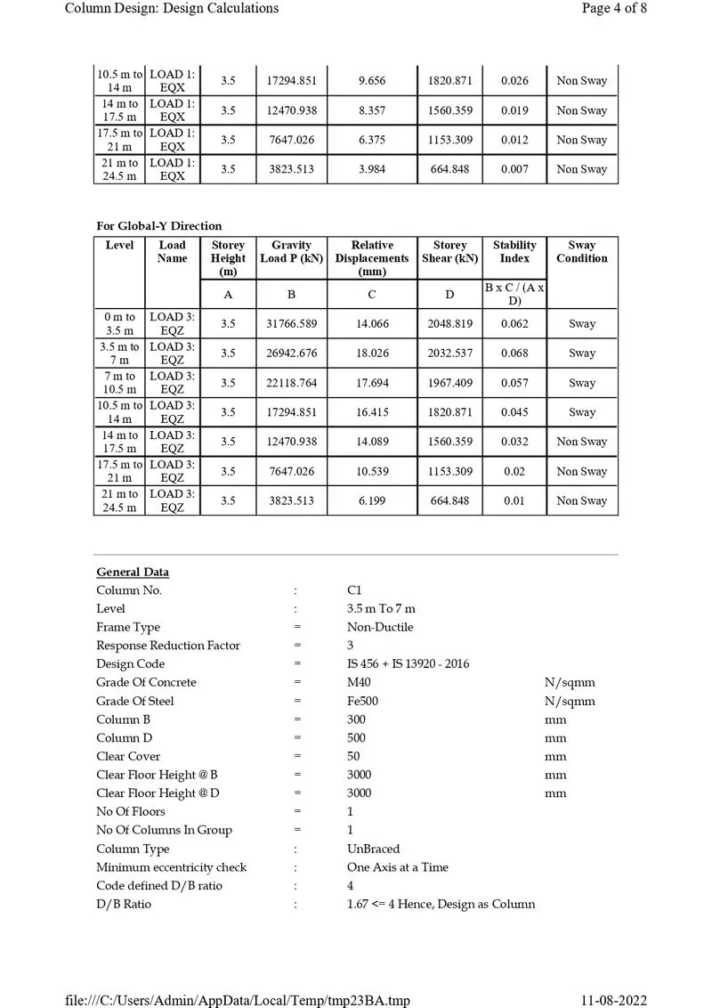
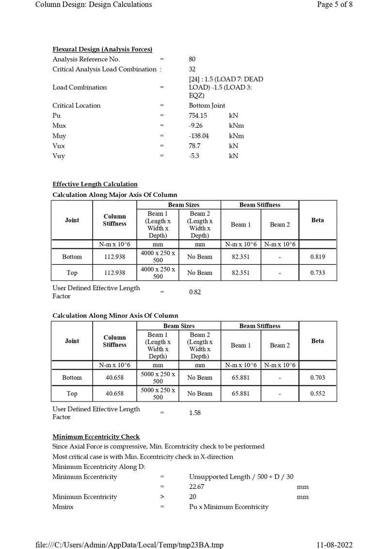
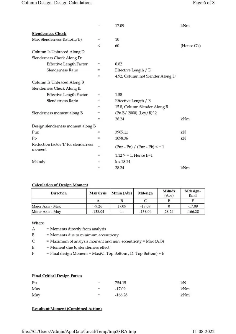
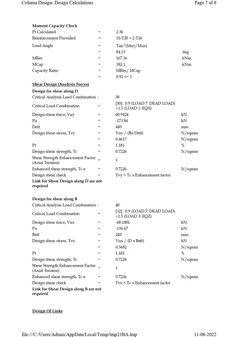
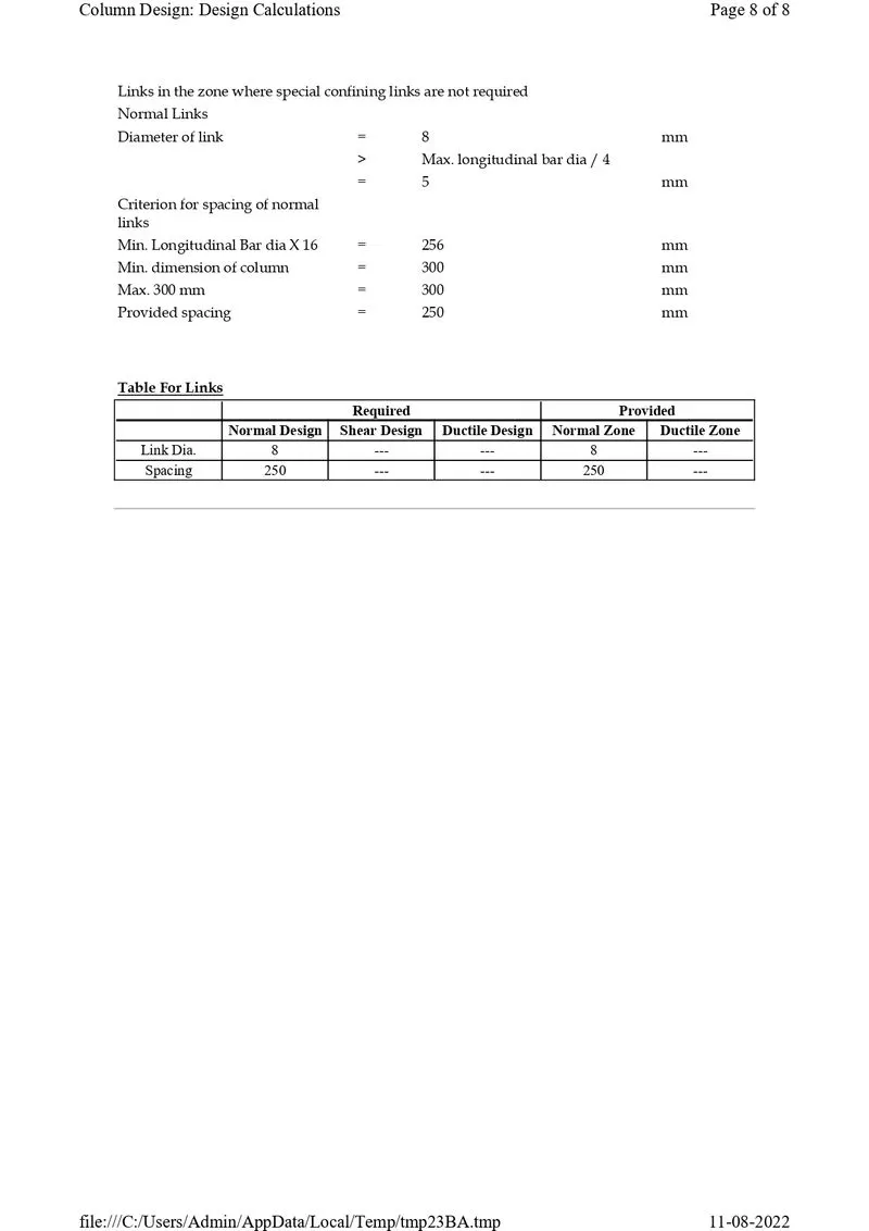
COLUMN STAAD RCDC :-
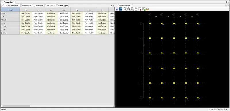
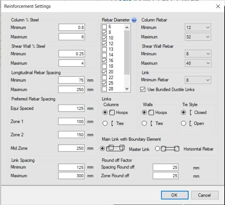
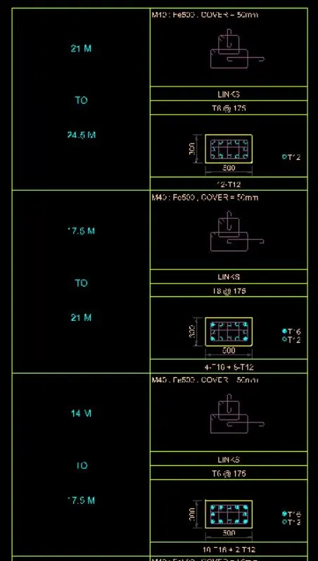
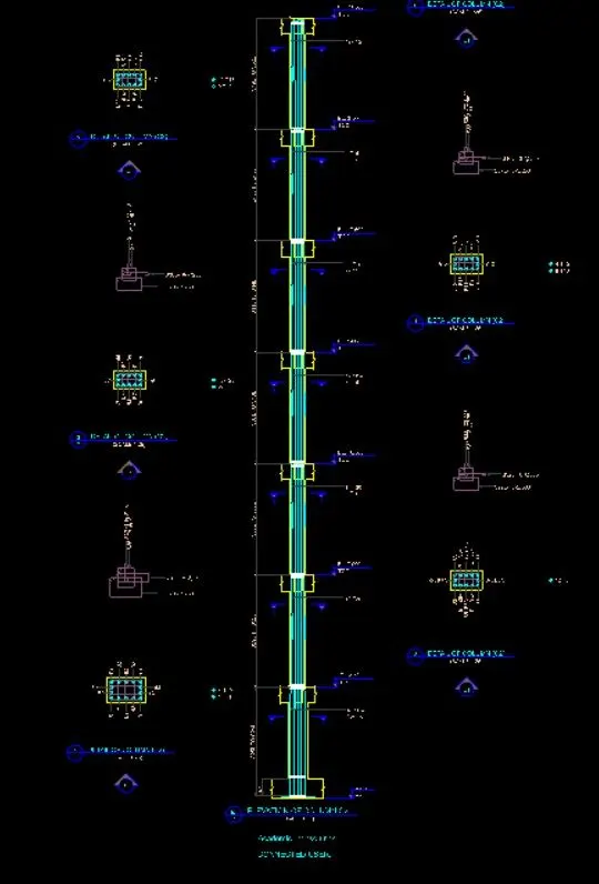
Design calculation report:
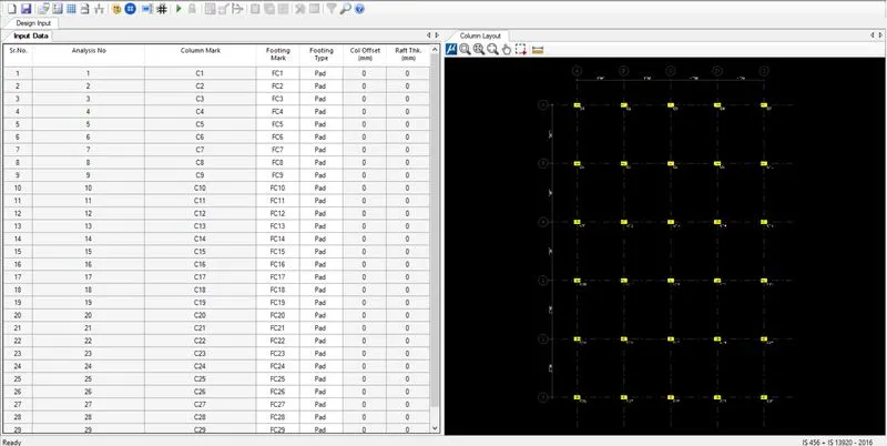
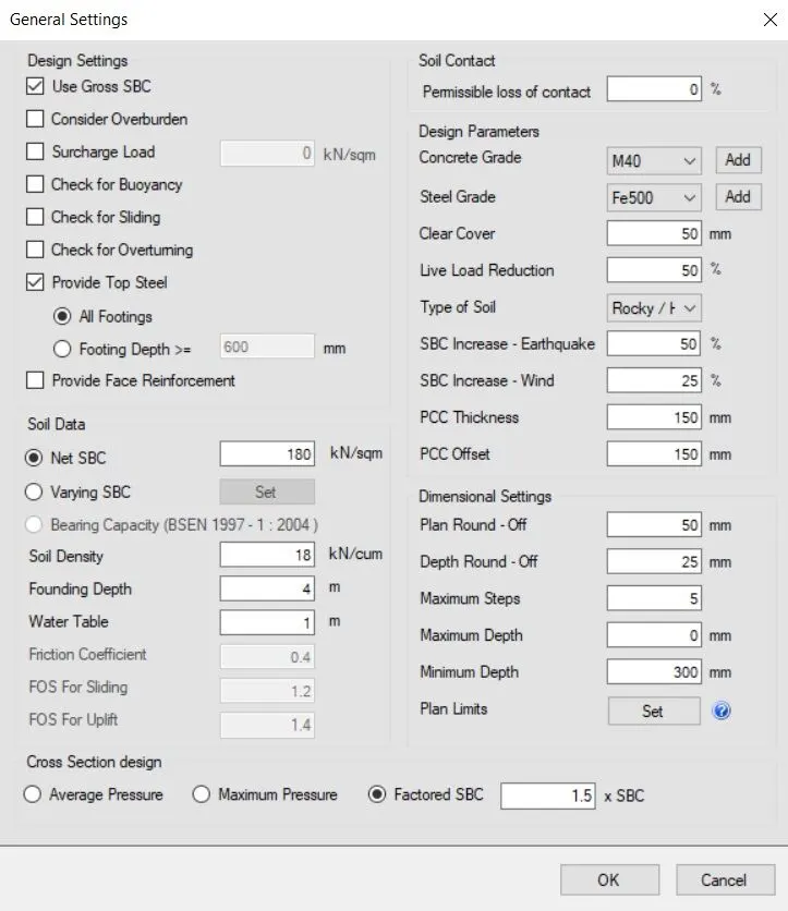
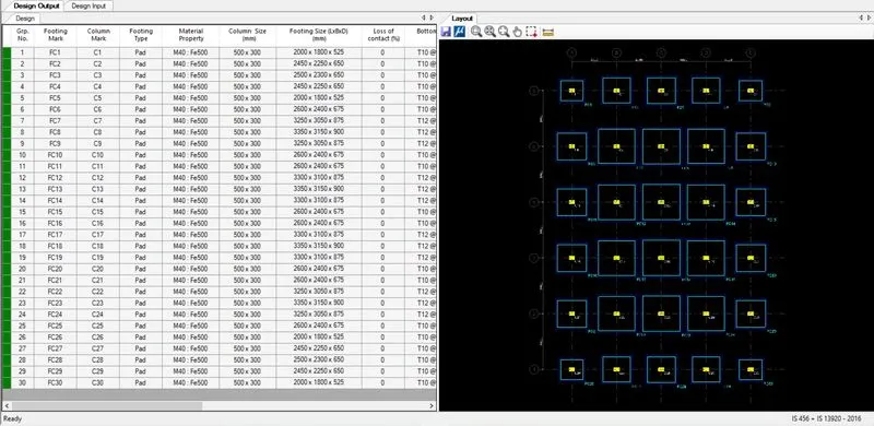
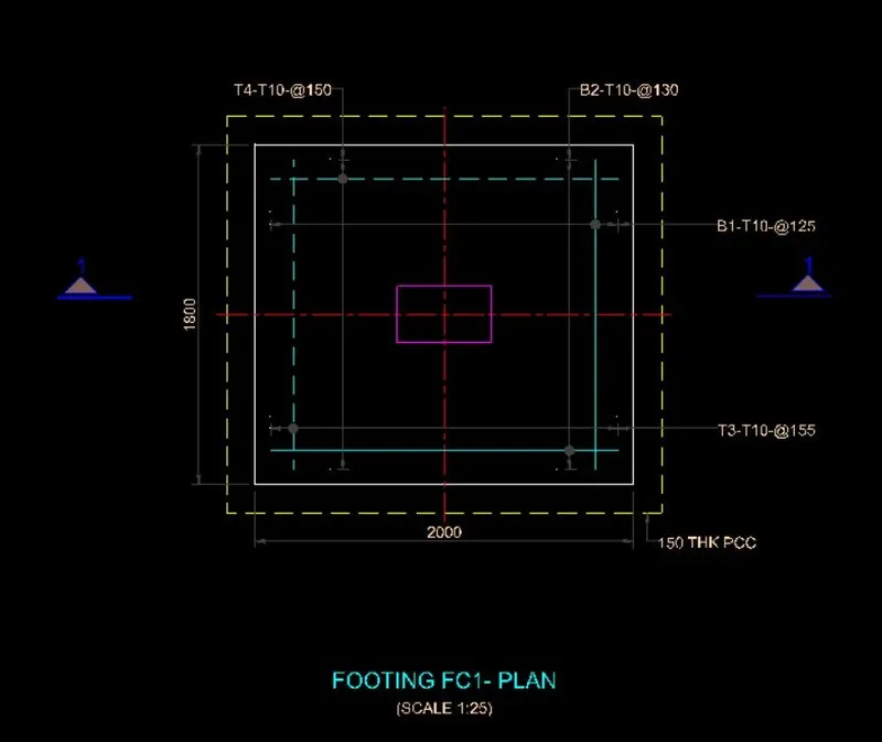
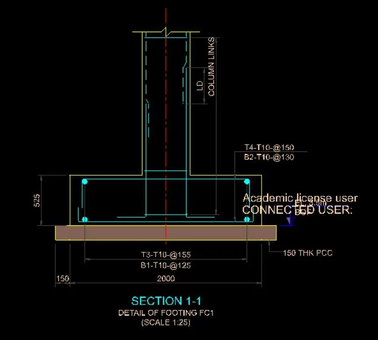
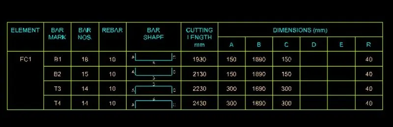
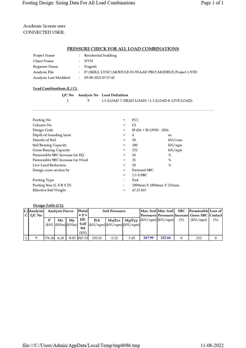
Design Foundations using STAAD Foundation.
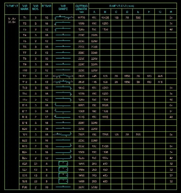
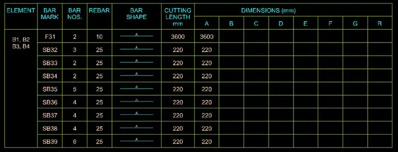
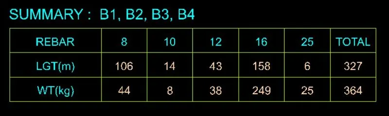
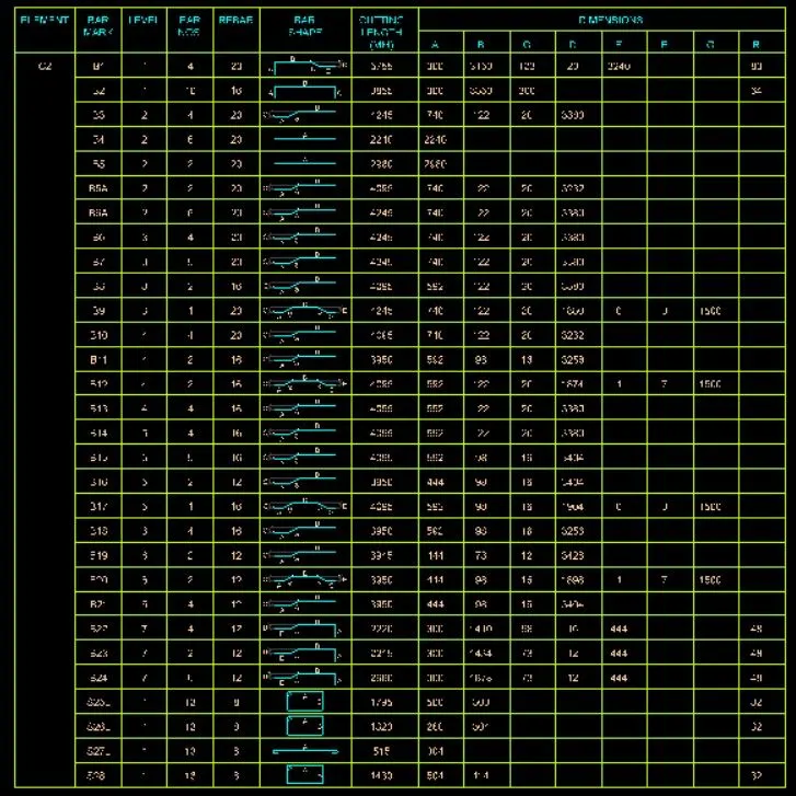
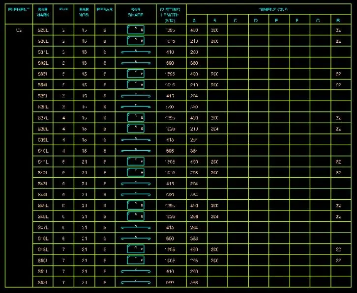
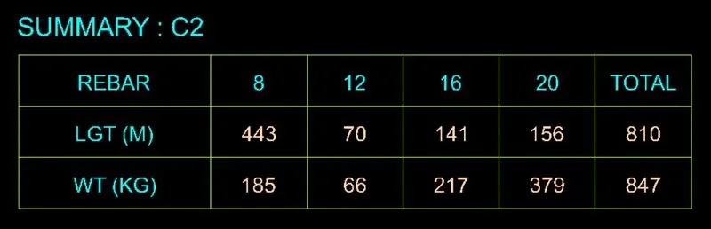
Prepare bar bending schedule for beam and column using STAAD RCDC :-
Bar Bending Schedule for BEAM :-
Bar Bending Schedule for COLUMNn :-
RESULT :-
- Design of a Multi-Storey Residential Building located in Bangalore using STAAD Pro Connect Edition is successfully completed.The specification, assumptions and design parameter with reference to Indian Standards.Assumed suitable sections for structural elements. Followed by IS 456, IS1893 and IS 875 part-1,2 &3.