Project 1
STEPS INVOLVED
- Lets download all the required components
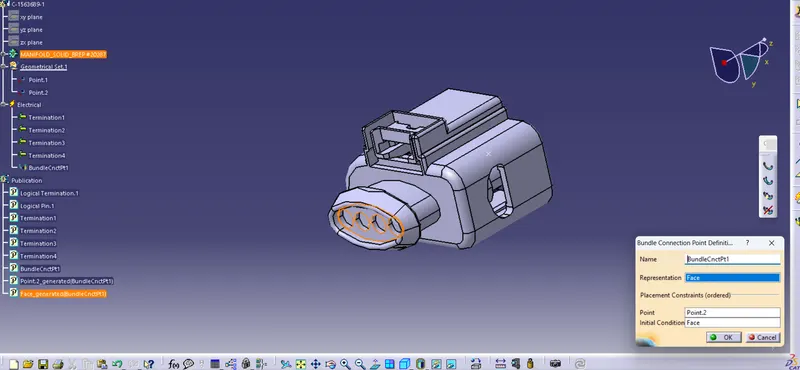
- Define the connector as an electrical part and define the bundle point, and connector connection point of all the connector
- Add the connectors in to the connector catalogue
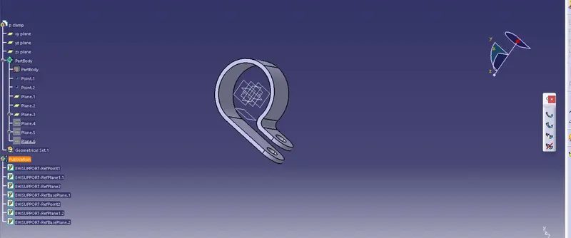
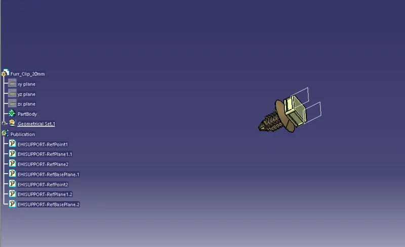
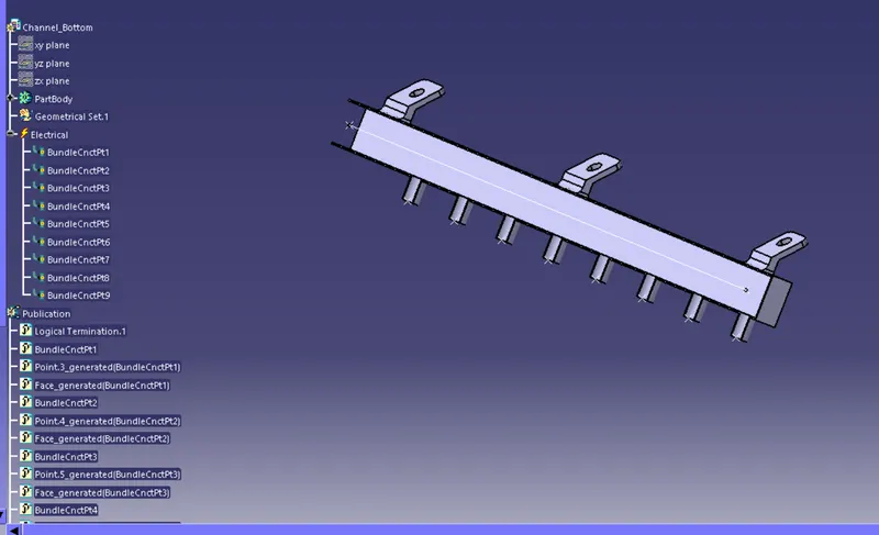
- After defining all the connectors , fir tree clip, p clamp and channel bottom , create a context file and name it
- Create a product file for geometric bundle assembly and insert all the electrical parts in to this product file
- copy the geometric bundle assembly in to main context file
- copy the engine CAD file in to context file
- Arrange the connectors ,cavity clip, p clamps, guiding channel according to the layout
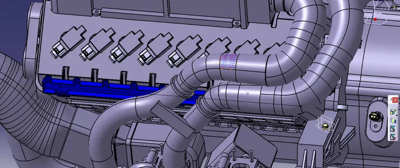
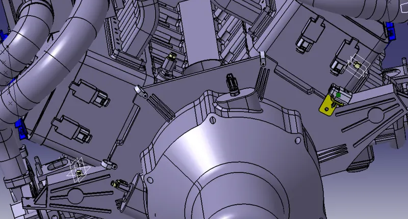
- Now lets start the routing
- Lets activate geometrical bundle and click on geomtrical bundle assembly product file
- start the routing from inline connector
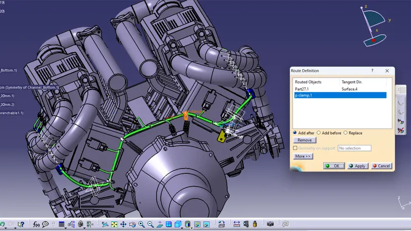
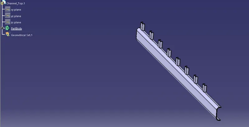
After completing the entire routing insert the channel over the against the guiding channel
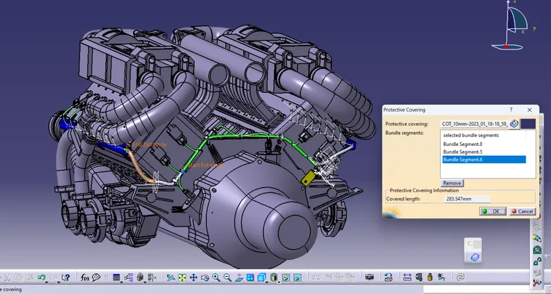
Before going to flattening lets add COT tube around it
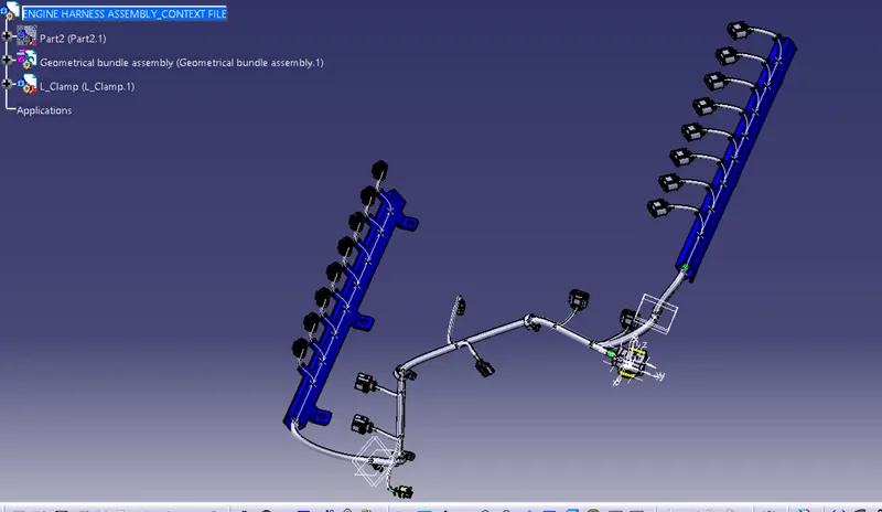
FLATTENING
- Create a product file and name it as flattening assembly
- switch to flattening workbench
- Initialize the flattening parameters
- Extract the geometrical bundle assemblyfile
- Click on flatten and select the face and select all bundles
- Use the appropriate command to modify the flattened assmbly according to your perspective
- After flattening manipulate the clips or connectors to the front view inorder to view properly
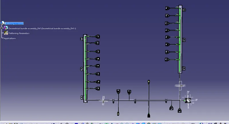
DRAWING FILE
- Create a new drawing file and save it
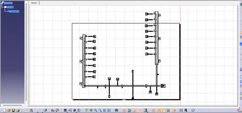
- Click on front view and select the face from the flattening assembly file
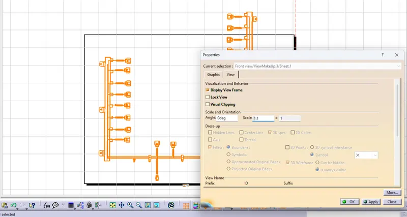
- After importing 2D file in to drawing change the view properties