Project 1
PROJECT 1 IN STAAD PRO
- Design a multi-storey Residential Building located in Bangalore using STAAD Pro Connect Edition. The specification must be as follows:
|
Building floors |
G + 6 + R |
|
Plan dimension |
B = 25m , L = 16m |
|
Storey Height |
h = 3.5m |
|
Soil |
Hard soil |
|
Use |
Residential Purpose |
|
Safe Bearing Capacity |
180 kN/m2 |
|
Maximum slab thickness |
150mm |
Assume suitable sections for structural elements. Follow IS456, IS1893 and IS 875
- Prepare a Design Basis Report for the project
- Create structural model using STAAD Pro Connect Edition
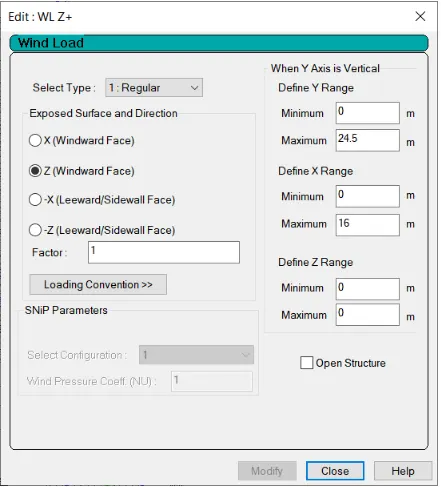
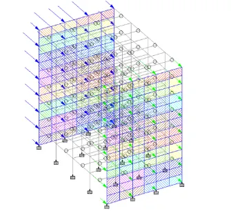
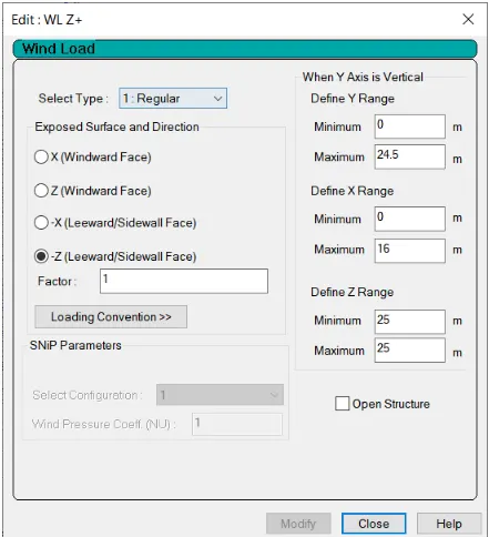
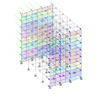
- Prepare DL, LL, WL and EQL load calculations as per IS 875 standards
- Design slab element using MS – Excel
- Design beam and column element using STAAD RCDC. Attach the design calculation report.
- Design Foundations using STAAD Foundation.
- Prepare bar bending schedule for beam and column using STAAD RCDC
- Attach necessary sketches and drawings wherever required.
- All stipulations, assumptions and design parameter must adhere to Indian Standards.
Aim:- To design a multi-storey Residential Building located in Bangalore using STAAD Pro Connect Edition
Procedure:-
Unit weight of the materials
Reinforced Cement Concrete = 2525 kN/m3kN/m3
Plain Cement Concrete = 2424 kN/m3kN/m3
Cement Concrete Screed = 2020 kN/m3kN/m3
Cement Masonry Units = 2222 kN/m3kN/m3
Structural Steel = 78.578.5 kN/m3kN/m3
Soil = 1818 kN/m3kN/m3
Dead Load
Floor slab
Slab weight = 3.753.75 kN/m2kN/m2 (0.15m×25kN/m3)(0.15m×25kN/m3)
Partitions = 1.51.5 kN/m2kN/m2
Floor Finish = 2.52.5 kN/m2kN/m2
Miscellaneous = 11 kN/m2kN/m2
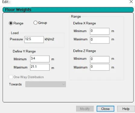
Total Floor Load = 8.75 kN/m2
Roof slab
Slab weight = 3.753.75 kN/m2kN/m2 (0.15m×25kN/m3)(0.15m×25kN/m3)
Insulaions and Water Proofing = 0.50.5 kN/m2kN/m2
MEP Services = 0.50.5 kN/m2kN/m2
Miscellaneous = 0.50.5 kN/m2kN/m2
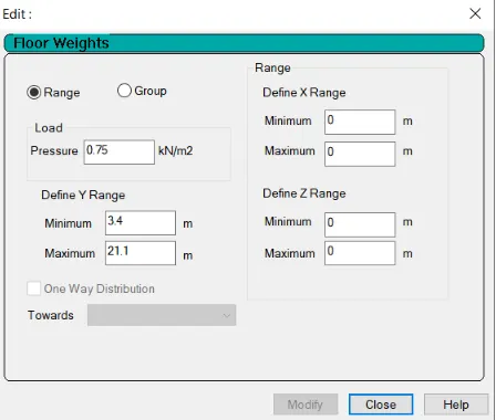
Total Roof Load = 5.25 kN/m2kN/m2
Live Load
Floor slab
Common Corridor = 33 kN/m2kN/m2
Total Floor Load = 3 kN/m2kN/m2
Roof slab
Accessible Roof = 1.51.5 kN/m2kN/m2
Total Roof Load = 1.5 kN/m2
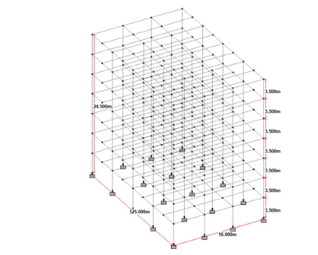
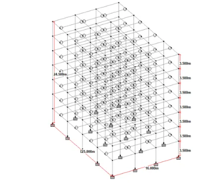
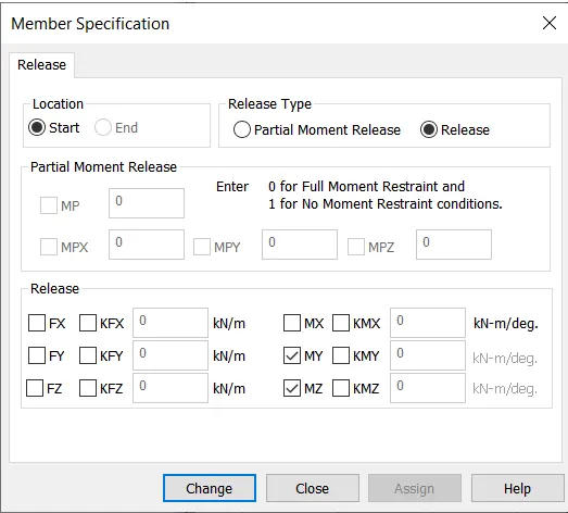
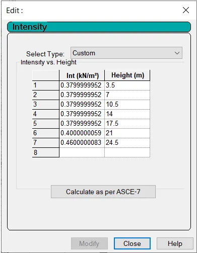
|
Basic data |
|||||||||||
|
Ly |
3.125 |
m |
|||||||||
|
Lx |
5.5 |
m |
shorter span |
||||||||
|
Thickness of supports |
longer |
6 |
m |
||||||||
|
shorter |
4 |
m |
|||||||||
|
Grade of concrete |
fck |
25 |
N/mm2 |
M25 |
|||||||
|
Grade of steel |
fy |
415 |
N/mm2 |
Fe500 |
|||||||
|
clear cover |
25 |
mm |
|||||||||
|
Design factors |
xumax/d |
0.48 |
N.A. factor |
||||||||
|
Qlim |
3.44 |
M.R. factor |
|||||||||
|
Ptmax |
1.19 |
% r/f |
|||||||||
|
Aspect ratio |
Ly/Lx |
0.568181818 |
|||||||||
|
TRUE |
DESIGN SLAB AS TWO WAY SLAB |
|||||||||
|
Assumptions for the depth of slab |
cl 24.1, pg-39 |
||||||||||
|
MF |
1.5 |
for Lx |
|
||||||||
|
|
& LL |
3 KN/m2 |
|||||||||
|
d |
141.03 |
mm |
|||||||||
|
dassumed |
150 |
mm |
|||||||||
|
Dassumed |
180 |
mm |
|||||||||
|
Computation of loading and B.M |
|||||||||||
|
S.Wt. |
4.5 |
KN/m |
else use cl 23.2.1, pg-37 |
||||||||
|
F.F |
0.8 |
KN/m |
|||||||||
|
L.L |
3 |
KN/m |
|||||||||
|
Total Load |
W |
8.3 |
KN/m |
||||||||
|
Factored load |
Wu |
12.45 |
KN/m |
||||||||
|
Effective spans Leffective: |
(as per cl 22.2, pg-34, IS 456-2000) |
||||||||||
|
For Lxeff |
|||||||||||
|
c/c between supports |
9.5 |
m |
|||||||||
|
clear span + d |
5.65 |
m |
|||||||||
|
Lxeff |
5.65 |
m |
|||||||||
|
For Lyeff |
|||||||||||
|
c/c between supports |
9.125 |
||||||||||
|
clear span + d |
3.275 |
||||||||||
|
Lyeff |
3.275 |
m |
|||||||||
|
Type of panel |
TWO ADJACENT EDGE DISC. |
||||||||||
|
Ly/Lx |
5.76 |
||||||||||
|
αx (Cont. edge) |
0.288 |
INTERPOLATED VALUE: |
|||||||||
|
αx (Mid-span) |
0.228 |
Ly/Lx |
αx (Cont.edge) |
αx (Mid-span) |
|||||||
|
αy (Cont. edge) |
0.047 |
1.2 |
0.06 |
0.045 |
|||||||
|
αy (Mid-span) |
0.035 |
5.76 |
0.288 |
0.228 |
|||||||
|
1.3 |
0.065 |
0.049 |
|||||||||
|
For span Lx |
|||||||||||
|
Mux,mid-span |
90.44 |
KNm |
|||||||||
|
Mux,cont.edge |
114.54 |
KNm |
|||||||||
|
for span Ly |
|||||||||||
|
Muy,mid-span |
13.91 |
KNm |
|||||||||
|
Muy,cont.edge |
18.68 |
KNm |
|||||||||
|
Required depth of slab |
|||||||||||
|
Mumax |
114.54 |
KNm |
|||||||||
|
dreq |
182.36 |
mm |
|||||||||
|
check dreq < dassumed |
TRUE |
||||||||||
|
dprovided |
150 |
mm |
|||||||||
|
Dprovided |
180 |
mm |
|||||||||
|
R/F area at bottom |
|||||||||||
|
In middle-strip |
|||||||||||
|
Direction |
Astrequired in mm2 |
φ (mm) |
Srequired in mm |
Sprovided in mm |
Astprovided in mm2 |
||||||
|
SHORT (X) |
2212.53 |
16 |
90.87 |
90 |
2234.02 |
||||||
|
LONG (Y) |
264.73 |
16 |
759.49 |
300 |
670.21 |
||||||
|
Spacing required = |
|||||||||||
|
Edge strip R/F along continuous edge |
|
||||||||||
|
Direction |
Astrequired in mm2 |
φ (mm) |
Srequired in mm |
Sprovided in mm |
Astprovided in mm2 |
||||||
|
SHORT (X) |
3381.25 |
16 |
59.46 |
50 |
4021.24 |
||||||
|
LONG (Y) |
359.37 |
16 |
559.48 |
300 |
670.21 |
||||||
|
for HYSD bars, min R/F = 0.12% of b*D |
|||||||||||
|
Minimum R/F |
Astmin |
216 |
mm2 |
OK |
for MS bars, min R/F = 0.15% of b*D |
||||||
|
At discontinuous edges at top |
|||||||||||
|
provide 50% of +ve R/F at top = |
1452.11 |
mm2 |
|||||||||
|
OK |
|||||||||||
|
Therefore, at discontinuos edges required R/F area = |
1668.11 |
mm2 |
|||||||||
|
φ |
10 |
mm |
|||||||||
|
Srequired |
47.06 |
mm c/c |
|||||||||
|
Sprovided |
40 |
mm c/c |
|||||||||
|
Torsional reinforcement |
|||||||||||
|
Torsion R/F at corner with both edge discontinuous |
1675.52 |
mm2 |
provide 34- 8 mm # |
||||||||
|
Torsion R/F at corner with one edge discontinuous |
837.76 |
mm2 |
provide 17- 8 mm # |
||||||||
|
Torsion R/F at corner with both edge continuous |
0.00 |
mm2 |
|||||||||
|
DESIGN SUMMARY |
|||||||||||
|
Depth of slab, D |
180 |
mm |
|||||||||
|
Effective depth, d |
150 |
mm |
|||||||||
|
R/F along X-direction (SHORT) |
|||||||||||
|
Ast,middle,bottom |
16# @ 90 mm c/c |
||||||||||
|
Ast,cont.edge,top |
16# @ 50 mm c/c |
||||||||||
|
R/F along Y-direction (LONG) |
|||||||||||
|
Ast,middle |
16# @ 300 mm c/c |
||||||||||
|
Ast,cont.edge |
16# @ 300 mm c/c |
||||||||||
|
R/F at discont. edges on top in both directions |
|||||||||||
|
Ast,edge,top |
10# @ 40 mm c/c |
||||||||||
|
AREA OF TORSION REINFORCEMENT |
|||||||||||
|
At corner with both edge disc. |
provide 34- 8 mm # |
||||||||||
|
At corner with one edge disc. |
provide 17- 8 mm # |
||||||||||
|
At corner with both edge cont. |
N.A |
||||||||||
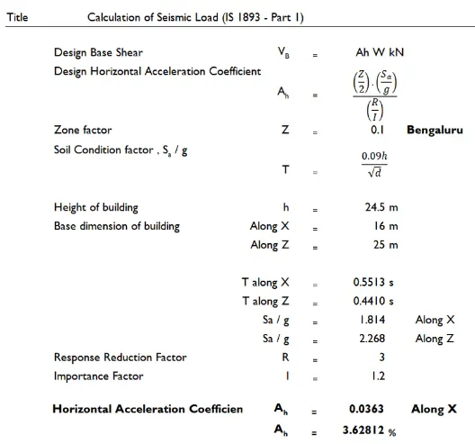
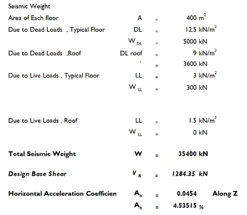
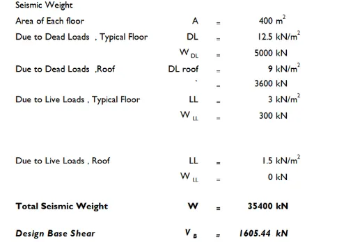
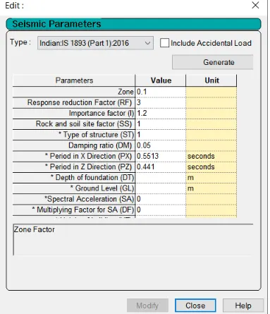

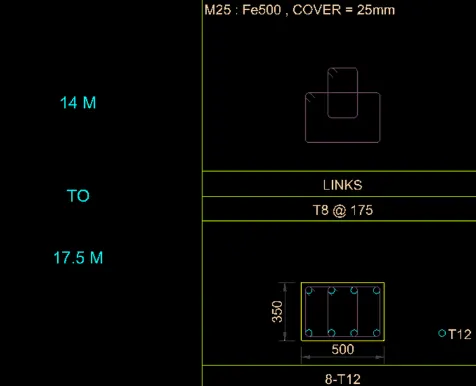
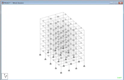
Result:-
The multi-storey Residential Building located in Bangalore is designed using STAAD Pro Connect Edition is done