Project 1
AIM
Define the Wiring harness on Given Engine and Prepare flatten view drawing in CATIA V5. Application of all Packaging rules, Industry best practices studied in this course shall be demonstrated in design. Apply Protection coverings as required.
PROCEDURE
Wiring harness is one the most essential parts of the vehicle industry. A wiring harness is an organized set of wires, terminals and connectors that run throughout the entire vehicle and transmit information and electric power, thereby playing a critical role in “connecting” a variety of components. Power and information travel through this network much like the circulatory and central nervous systems of the human body. It conducts electricity for all electrical loads on a vehicle.
Wiring harnesses contribute tremendously to manufacturers’ development and advancement of vehicles around the world. Automobiles or off-highway vehicles are driven in all kinds of environments, from cities to mountain villages, in the tropics as well as in cold climates. This means wiring harnesses must offer superior durability.
There are four main steps in electrical system design: selection of component, wiring diagram, wiring harness and electrical routing
SELECTION OF COMPONENT
Selection of connectors, fuses, lights, switches, sensors, wires, cables, relays, protection tubes, motors etc. are the core components of the wiring harness. The performance of these components directly determines the overall performance of the wiring harness and plays a decisive role in the stability and safety of the whole vehicle. The basis of the selection of these components is the voltage system and its current carrying capacity. Ambient temperature in the selection of these components is one of the most important aspects of wiring harness design. Proper selection of these electrical components and their conductors ensures reliability and safety. For example, for the requirements of high-performance airbags like ABS and ECU with a terminal connector, gold-plated pieces are preferred to ensure safety and reliability.
Wiring diagrams
Wiring diagrams are also known as schematics or circuit diagrams. The selected compound is placed and connected to each other in the diagram. These components belong to a set of libraries which can be modified and configured according to customer specific requirements. A modified and configured according to customer specific requirements. A wiring diagram shows each connection in detail. The schematics give an overview of the components that are part of the electrical design. Other items in the schematics are for example cables, sheet cross references and ECUs.
WIRING HARNESS
There are several factors to consider when designing a cable assembly or wire harness for your application. The wiring harness is designed once the schematics are ready.
The entire vehicle is divided accordingly. This process also involves generating a connection list and a BOM. Harness passes through many areas where it requires protection against heat, dust, moisture etc. Wire harness protection prevents damage caused by wire vibration damage, abrasions and incidental contact with other pieces of the heat-producing equipment.
Electrical routing
The lengths of the harnesses in the harness drawing are derived from the 3D models. Harness installation drawings are generated via 3D routing. The routing feature creates a unique type of subassembly which builds paths of electrical cables between the components. It ensures flexibility between two or more components and helps in deciding the path through which the cable should run to avoid further complexity. This helps in understanding the path followed by a particular harness.
P-Clamp
As the name says, we added a ratchet mechanism to the p-clamp. It gives users the power to fix the clamp separately from the fastening stage. A great additional feature is that you can release the ratchet mechanism, re-open the clamp and re-use it.
We matched the P-CLAMP features to the following usability requirements:
- Freedom of choice: separate pre- and final assembly stages.
- Easy installation: close with one-hand.
- Eliminate pinching: rifling centres the bundle automatically.
- Re-open, re-use: easy release with a flathead screwdriver.
- Reduce part inventory: four flexible sizes (6.2 mm - 51 mm diameter).
- Configure flexibly: multiple mounting plate dimensions available.
- Maximise durability: toughened, UV-resistant PA66 and corrosion-free steel.
- Optional extras: soft inserts and tension tab for repetitive quality.
Electrical Harness Design
The electrical harness requires two steps. You must first define the required connectors and connection points. Once you have these connections, you are ready to begin defining the geometric bundle that links the various connection points. These geometric bundles will behave as a space reservation for the wiring they will contain. In this section of the course, you will not be defining the actual wires within the geometric bundle, but rather just the overall size and shape of the geometric bundle that will contain the wiring. There are two workbenches involved in electrical harness design. They are the Electrical Harness Assembly and the Electrical Harness Installation workbenches. The Electrical Harness Assembly workbench will allow you to work with the geometric bundle as a whole. The Electrical Harness Installation workbench will allow you to define the specific bundle segment and route the bundle. The two workbenches are used simultaneously to define the geometric bundle. Although the Electrical Harness Installation workbench is a separate workbench, it is generally only accessed through the Electrical Harness Assembly workbench when defining a specific bundle segment. This is a similar behaviour to the Sketcher and Part Design workbenches. You generally do not access the sketcher workbench directly, but instead you access sketcher through the Part Design workbench. In our case, the Electrical Harness Assembly workbench works in the product environment, whereas the Electrical Harness Installation workbench works with a specific branch able part in the product. In this course, you will not be defining the specific wires within the geometric bundle. Instead, you will be defining the bundle as a whole for space reservation and connectivity information and not to define pin to pin connectivity. To define pin to pin connectivity, you will need to study the Electrical Wire Routing workbench. With that said, keep in mind, you can always define a geometric bundle per wire if desired. This will emulate defining specific connectivity, but you will find that it requires a lot of time and work when dealing with smaller wires.
Connector
we saw that the Installation and Equipment workbench can provide ease of installation, robust assembly behaviour and routine design reduction by automating the assembly on Electrical components. This post will show further capabilities on this topic, with a different combination of electrical links.
|
Icon |
Electrical Device Definition |
Electrical Connection Point Type Allowed |
Number |
Can Be Connected With |
Number |
 |
Connector (single connection point) |
Connector connection point |
1 |
Connector (single connection point) |
1 |
|
Connector (multiple connection point) |
1 |
||||
|
Back shell connection point |
∞ |
Back shell |
∞ |
||
|
Connector (multiple connection point) |
Connector connection point |
∞ |
Connector (single connection point) |
∞ |
|
|
Connector (multiple connection point) |
∞ |
||||
 |
Back shell |
Back shell connection point + Support part |
1 |
Connector (single connection point) |
1 |
|
Shell |
1 |
||||
 |
Shell |
Back shell connection point |
1 |
Back shell (if not connect to a back shell) |
1 |
|
Shell connection point |
1 |
Shell (if not connect to a back shell) |
1 |
FULLY CONNECTED BUNDLE SEGMENT
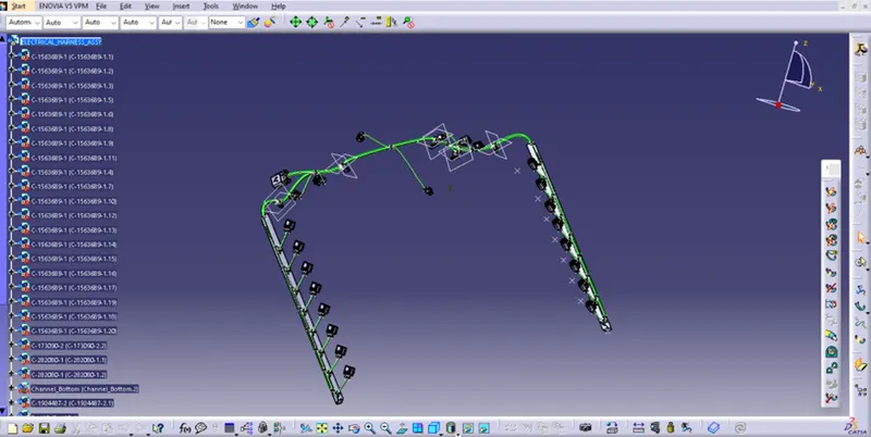
We first to the edit and select the search bar and go the advance select the work bench as electrical, type as bundle segment, attribute as fully connected and now select the search option and find the result as shown in the image.
WIRING HARNESS FLATNESS
In an industry in which manual engineering methods are still largely dominant, innovative approaches can significantly reduce the harness design cycle time and cost, improve product and process quality, and reduce harness manufacturing turnaround time and costs. With thin margins coupled with large volumes, improvements to efficiency, cost reductions, and production time can significantly impact profitability and long-term business sustainability. In this white paper, learn how solutions utilizing high levels of automation, data coherency, and robust integrations can do just that.
SOLUTION METHODOLOGY:
Step - 1:
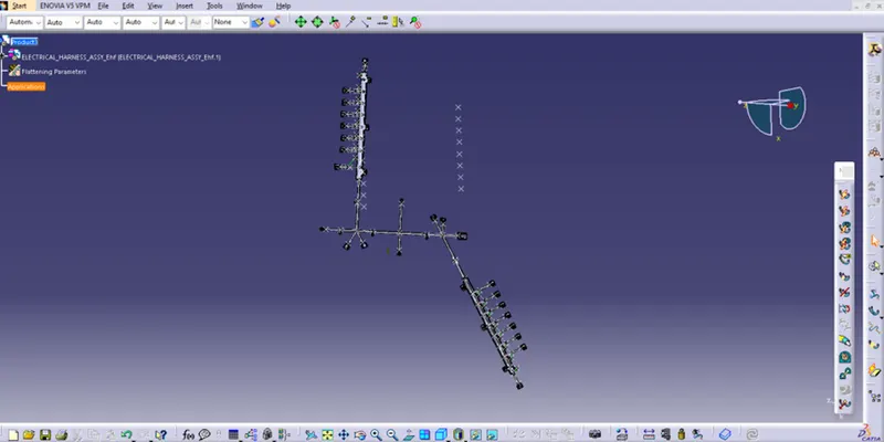
- Create a product file and navigate to the Electrical Harness Flattening for wire harness flattening option and save it in the same location where the wire harness or routing assembly is stored.
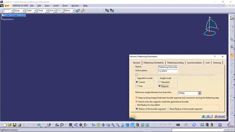
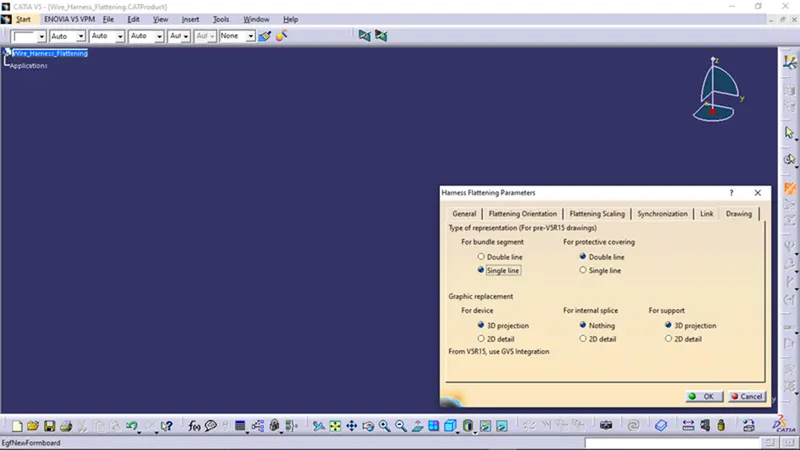
- Define the 'Harness flattening parameters' in order to flatten the required wire harness assembly.
- While defining the harness flattening parameters in the drawing menu single line is selected for bundle segment and double line is selected for protective coverings in order to differentiate between the wire bundle and cot tubes in drafting.
Step - 2:
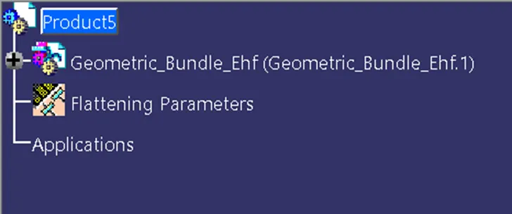
- Select the 'Extract' option from the Electrical Harness flattening workbench and select the Geometric bundle product in the wire harness assembly product file.
- Then wire harness assembly is imported to the Wire flattening product file with 'EHF' extension added to the geometric bundle assembly name.
Step - 3:
- Select the 'Flatten' option to flatten the wire harness assembly.
- Then select the active plane, then select any one branch and then select the 'select all branches'.
- If there is no discontinuity in the bundle segment then all the branches will be selected and by pressing 'ok' the wire harness assembly will be flattened.
Step - 4:
- Use 'Rotate' and other commands to rotate the branches and bring them in proper orientation as per the given layout.
Step - 5:
- Save the product file using 'Save management' option so that all the related product files and part files are stored in single directory.
FOR DRAFTING:
Step - 1:
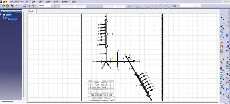
- Create a new drawing file and save the file in the same location.
Step - 2:
- Insert the title block template and fill up the required details.
Step - 3:
- Add the front view of the harness assembly by selecting any one of the flat faces of the connector and orient the view as per the requirement.
Step - 4:
- Go to the properties of the view and select the '3D Wireframe' on and ' Is always visible' option in order to see properly the Wire bundle, connectors and the protection coverings.
Step - 5:
- Show and name all the parts used in the wire harness assembly in form of a table.
CONCLUSION:
- From the above assignment we learnt how to flatten a given wire harness assembly and how to place the flattened view on a drawing sheet and show all its components.