Project 1
Aim :
1. Create Civil 3D Design File.
2. Create surface File & Create Surface by using given Survey Data.
3. Create Alignment by Using Proper Geometry Standard & apply Supeelevation.
4.Create View frames & sheet & create seperate .dst file for the same.
5. Workout quantity by using civil 3d.
PROJECT 01 DELIVERABLES
All .DWG files related to the project
The summary Excel spreadsheets linked to the .DWG files
The project estimate (.XLS or .XLSX)
A.PDF plan set of complete project
1. Create Civil 3D Design File.
- Open civil 3d impreal.
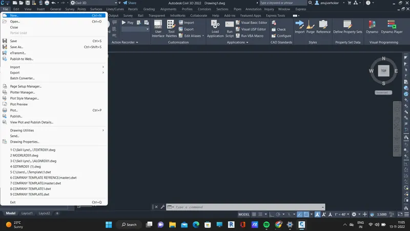
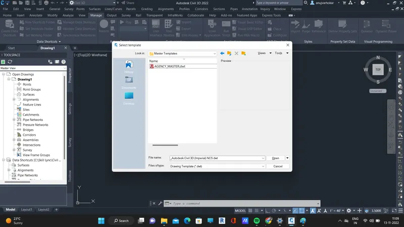
- After opening civil 3d interface civil 3d click on new.
- Next select civil 3d imperial template from template file template folder.
- Select template file rename to company xyz template file and save the file in project location.
- After creating template file add layer. dimension style, label style block,text style and layout.
2. Create surface File & Create Surface by using given Survey Data.
- Click on setting in tool box edit drawing style and set cordinate system in template file .
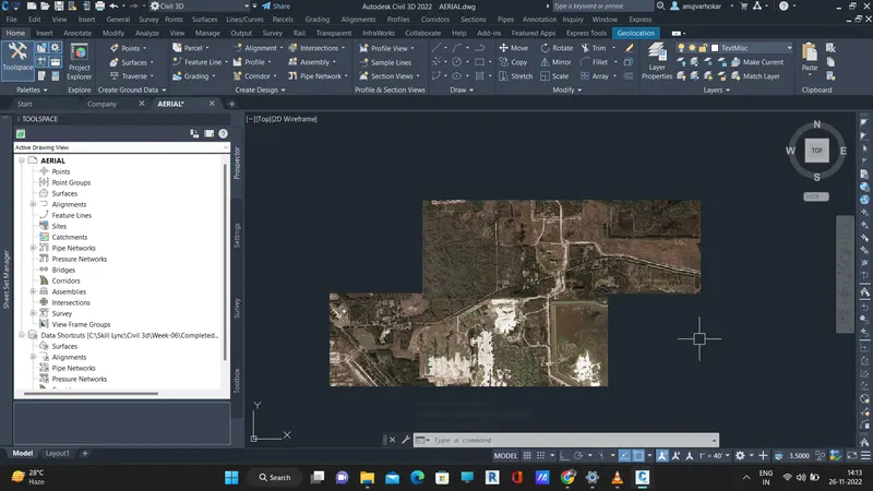
- Type mapinsert command for upload aerial images upload images in company xyz dwt file.
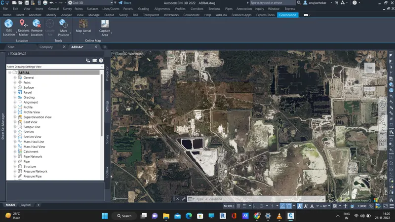
- Click on geolocation open map aerial and chek the images proper set on codinates or not.
- Using t frame command remove all borders.
- Using File nameing convention give the name AERIAL.dwg and save.
3. Create Alignment by Using Proper Geometry Standard & apply Supeelevation.
- Create new file using company dwt file.
- Using file naming convention give the name ALGNRD.dwg and save the file in project 01 folder.
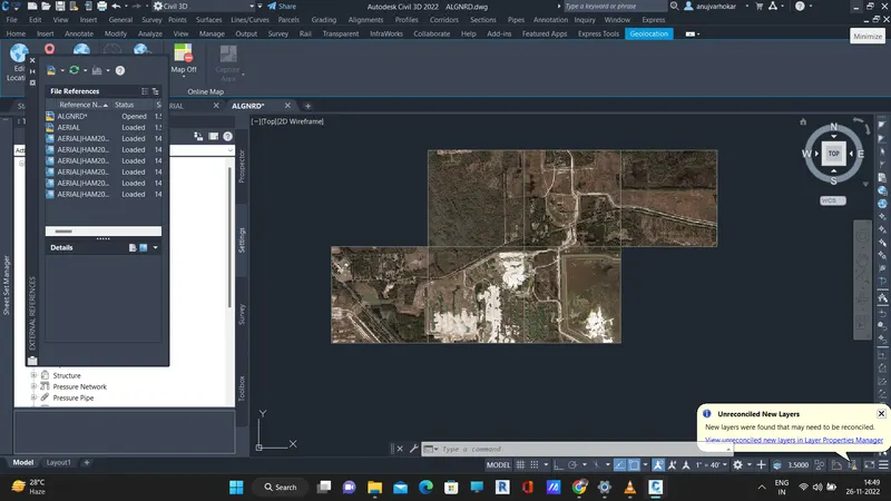
- Set cordinate and attach AERIAL.dwg file in ALGNRD.dwg file.
- Type command xref to attach AERIAL file in ALGNRD.dwg.
- Open Aerial map to check proper location cordinates and aerial file cordinates.
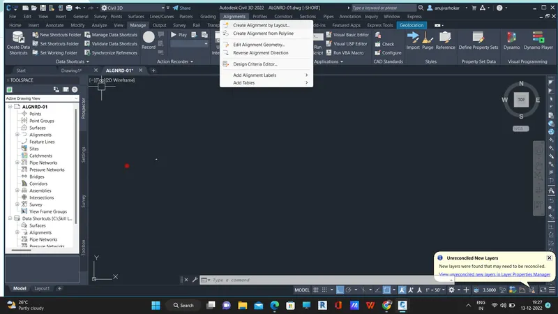
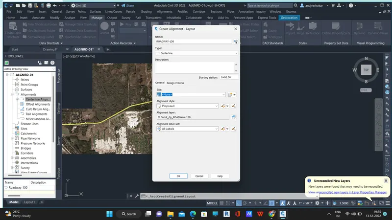
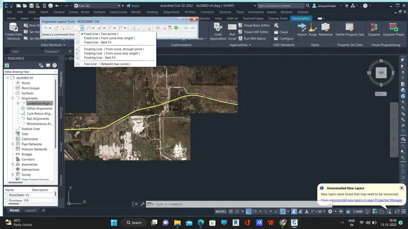
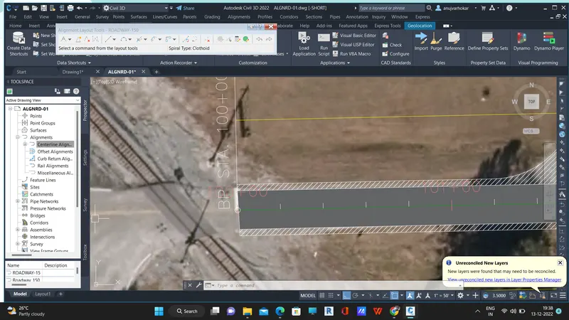
- After insert aerial images in proper cordinates click on Alignment \ createaligment from layout\ create alignment layout give the name of alignment road way-150 then alignment tool was open the select a command from alignment tools.
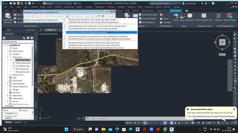
- Create aligment using command fixed line (two points) \ Free spiral- curve spiral between two entities.
- As per given in tcs drawing in project resources take center using road width given in drawing and draw the aligment.
- Create new file using company _xyz.dwt file.
- Click on manage\ set working folder in completed project folder.
- Create new shortcut folder give the name _shortcuts
- Set shortcut folder as _shorcuts right click on data shortcut click on associate project to current drawing.
- Create data shortcut of alignment roadway-150 in company file.
- Create reference of alignment roadway-150 in current file.
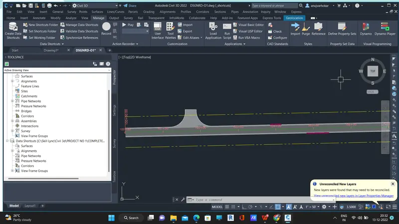
- Using layer give the 24 feet proposed width and draft the design of road using layer and take reference from tcs drawing.
- Save the file as DSGNRD.dwg
4.Create View frames & sheet & create seperate .dst file for the same.
- Ceate new dwt file and give the name plansheet.dwt file.
- Set the scale 1':50" .
- Click on layout copy title block scale 1':50" and lock.
- Type (vports) for select dual viewport create view port in title box .
- Type (pr) for properties give the proper defination to the view ports and save.
- Click on layout and give the name dual plan scale 1:50.
- Press ctrl+p select plot style tabel give the name proj 11 * 17 proj 1 select 11 *17 paper size.
- Repeat similar process for single view port on select single viewport and remaining process was same.
- Rename as Single plan 1:50 scale
- Save the dwt file as Plansheet.dwt file.
- Create new file using company-xyz.dwt file.
- Create data shortcut of alignment roadway -150 in current file.
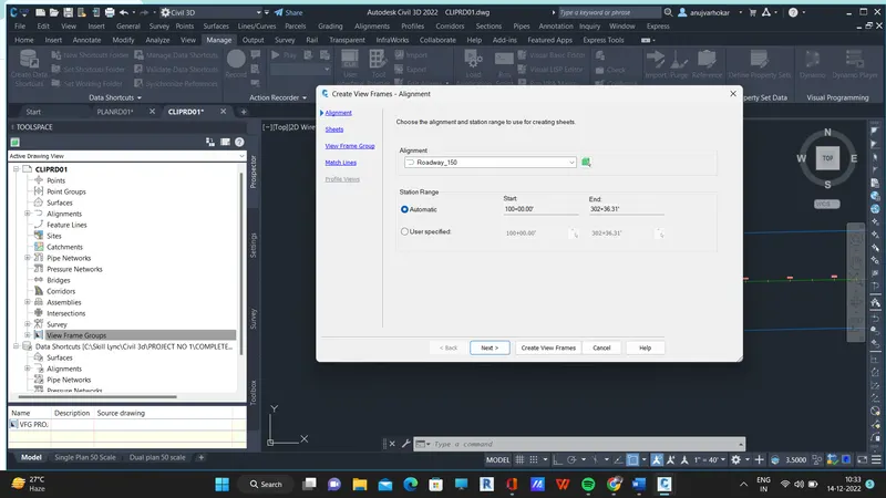
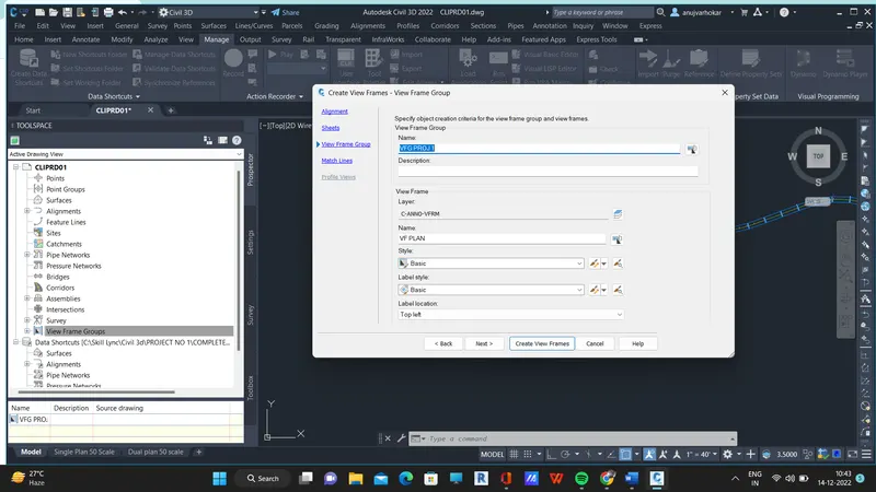
- Right Click on viewframe click on create view frame.
- Choose aligment and station for use creating sheet .
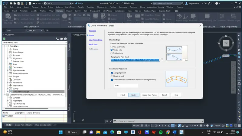
- Choose sheet type and make setting for the view frame. Select dwt file already have view port select plansheet dwt file and choose DUAL PLAN 1:50 SACLE
- Specify the object creation criteria for view frame group and view frame.
- Choose insert mathch line automaticaly and define how they are place.
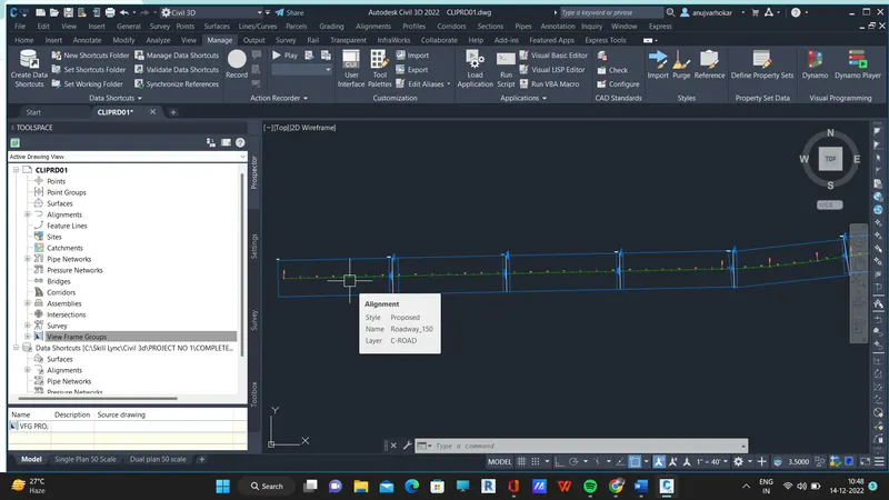
- Click on create view frame.
- Save the file as CLIPRD01 completed project location.
- Create data shortcut view frame and alignment roadway 150 in current drawing.
- Open priviously save file PLANSHEET.DWT FILE create reference viewframe and aligment in plansheet.dwt file.
- Before creating sheet type CTRL+4 for create dst file.
- Give the name project01.dst.
- Right click on project .dst create to new subset folder give the name Rodways plan And signing and markinng pavement.
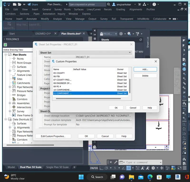
- Right click on project.dstclick on properties and edit custom properties.
- Save the file in completed assignment folder.
- Back to plansheet.dwt file.
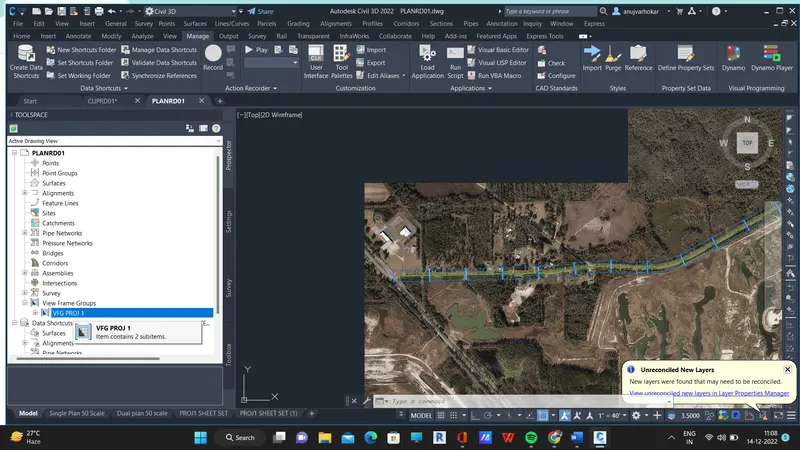
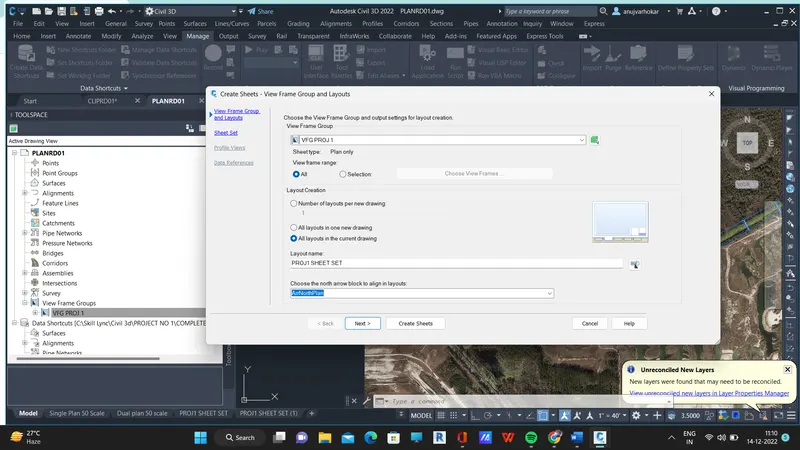
- Right click on view frame proj 1click on create sheet.
- Choose the view frame group and output setting for layout creation.
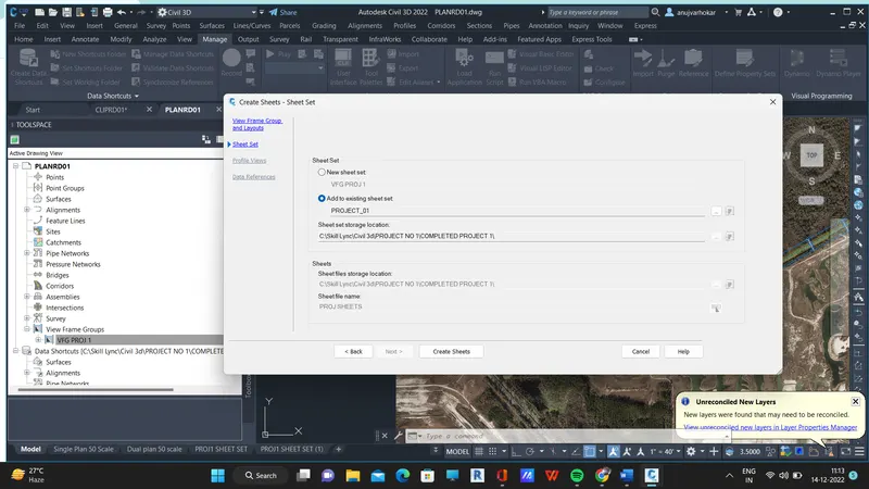
- Add existing sheet set and choose sheet file storage location and create sheets.
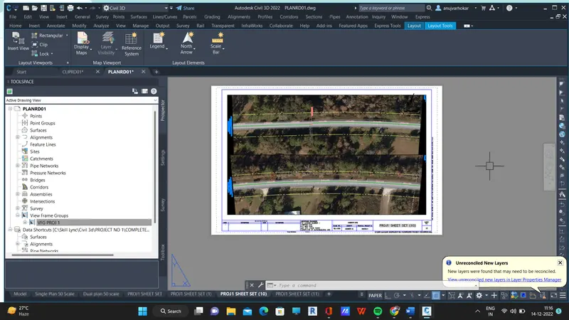
- Save the file as PLANRD01
- OPen project .dst file import KEYSRD01 and import all sheet in PLANRD01.dwg files sheet in subset Roadway plans.
- Rename and re number all the sheet.
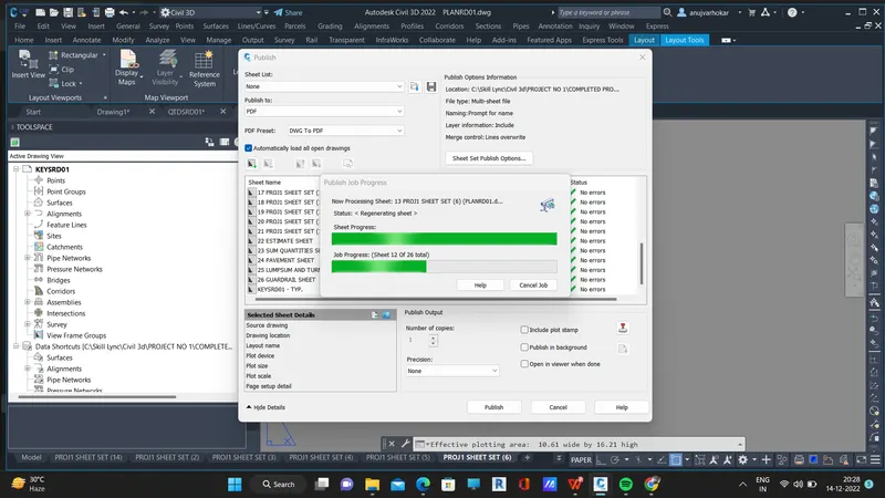
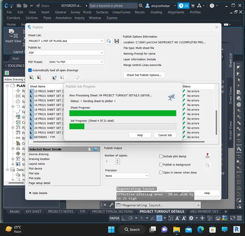
- Click on roadway plan click on publish then click on publish dialog box chek the sheet set the 11 into 17 paper size set storage location and create pdf file of all sheet save in completed project folder.
5. Workout quantity by using civil 3d.
- Create a new template file using company _xyz.dwt
- Open the fiile DSGNRD01.dwg copy the drawing in new file
- Click on edit paste to the orignal cordinates and save as QTSRS01.
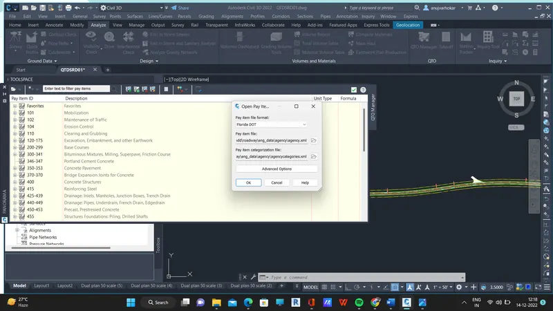
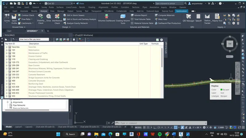
- Click on analyze Click on QTO manager open panorama window click on file sign given in panorama window select pay iteem file format ,select pay item file and pay item caategorization and click on ok .
- Pay item material list was open note the payitem id given in excel sheet and select in panorama window assign to pay item from drawing slecet the object when object was selected was hatch create add in favorite list.
- Similar process for all different material pay items. ( But we select any rectangular or any other shape object the n click on assign to pay item area.)
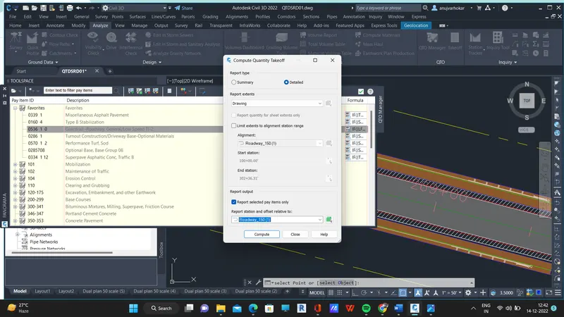
- Select required pay item id of material previosly selected panorama window favorite list.
- Click on execute take off commmand.
- Mark on detailed then select reported select pay item only select aligment and clcik on compute.
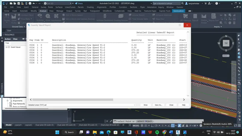
- Then select summary detailed area .html them see the detailed linear take off report.
- Repeat the process for all pay item id.
- Link the quantity using summary Excel sheet and create a layout.
- For create right click on layout click on move and copy select5 before layout and create new layout rename .
- Upolad single plan 1' :50" sheet from Plansheet .dwt file.give the proper defination.
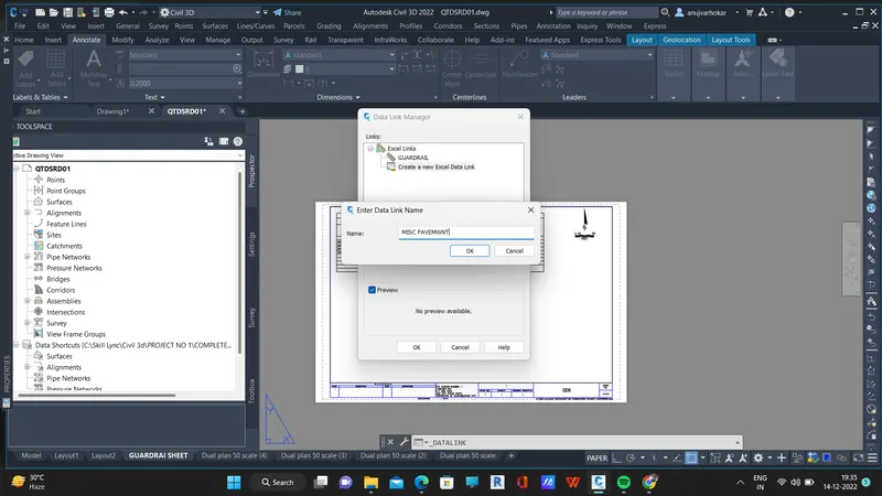
- For insert excel file in sheet go to the annote click on data link click on create create excel link give the name choose the file which are import in sheet clcick on ok.
- Click on table select data link select sheet and press ok and enter sheet in title box.
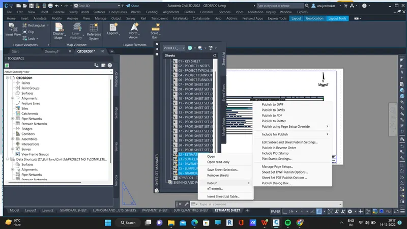
- For update the . pdf plan set to include the quantity summary sheet press ctrl 4 open sheet set manager.
- Right click on project slect import layout sheet .
- Select file QTDSRD01 file import and check.
- Click on publish click on publish to dialog box choose the pdf then file save location click ok.
- Convert all drawing sheet into pdf sheet.
- Click on publish click on publish to dialog box choose the pdf then file save location click ok.
- Convert all drawing sheet into pdf sheet.
- Create estimate bid form given project no 1.