Planetary Gear in Solidworks
AIM : To design and analyse planetary gear system in Solidworks.
OBJECTIVES :
- To create internal ring gear with following properties -
- Module = 2.5 (You must use the metric system in design modeler)
- Number of teeth = 46
- To create sun gear with following properties -
- Sun Gear
- Number of teeth = 14
- Input Speed of the Gear = 200 rpm.
- Number of planet gears = 4
- The dimensions of the carrier depend on the shaft diameter of the planet gear.
- With the above input parameters, you are going to run a simulation on the following cases,
|
Input | Output | Fixed | ||
| 1 | Sun Gear |
|
|
||
| 2 |
|
|
Sun Gear | ||
| 3 | Sun Gear |
|
|
- Input- Rotary Motion given to that part as input.
- Output- After motion analysis, Angular Velocity of that part is plotted as a graph.
- Fixed-Make that particular component as a fixed part.
- The module is the same for all the gears.
- Note - Gear mates are not to be used.
THEORY : A planetary gear set is made up of three types of gears; a sun gear, planet gears, and a ring gear. The sun gear is located at the center (yellow), and transmits torque to the planet gears (blue) which are typically mounted on a moveable carrier (green). The planet gears orbit around the sun gear and mesh with an outer ring gear (pink). Planetary gear systems can vary in complexity from very simple to intricate compound systems, depending on the application.
Planetary gears are often used when space and weight are an issue, but a large amount of speed reduction and torque are needed. This requirement applies to a variety of industries, including tractors and construction equipment where a large amount of torque is needed to drive the wheels. Other places you will find planetary gear sets include turbine engines, automatic transmissions, and even electric screwdrivers.
Planetary gear systems are able to produce a lot of torque because the load is shared among multiple planet gears. This arrangement also creates more contact surfaces and a larger contact area between the gears than a traditional parallel axis gear system. Because of this, in the load is more evenly distributed and therefore the gears are more resistant to damage.
PROCEDURE :
- 1. Calculations of the pitch circle diameter and the number of teeth for the planet gear -
- Since all the necessary parameters except pitch circle diameter and number of teeth for planet gears. It can be found by by basic geometry as,
- `m=D/T` , where `m` is module of gear, `D` is Diameter(pitch) , `T` is number of teeth on gear,
- From this equations, pitch diameter of Ring gear whose module is 2.5 and number of teeth are 46, comes out to be `115` m,
- Similarly, pitch diameter of Sun gear whose module is 2.5 and number of teeth are 14, comes out to be `35` m,
- From the geometric orientation of the system, the diameter(pitch) of planets gear can be found as,
- Since module is the same for all the gears.
- `implies` `D_r` = `D_s + 2*D_p` `implies` `D_p = 40` m, and number of teeth of planet gear as `16`
- A representation of the equations used above, the gear at the center is sun gear and planet gears surround it and all these are placed in a bigger gear called ring gear.
- 2. Designing 3D models of all components -
- For designing ring gear, either we can design according to all dimensions or we can import from Solidworks toolbox. The Ring gear is imported from Solidworks toolbox using ANSI metric system with following parameters as input -
- Similarly sun gear and planet gears are also imported from it and inputs are provided,
- The carrier can be made according to the design and orientations of planet gears. For this, sketches were drawn for different faces and were extruded accordingly,
- 3. Assembling all components -
- At first, carrier was inserted and and made to float from being fixed and made coincident with plane parallel to it's face and axis with the other two planes, making it to rotate about it's axis.
- Then other gears were inserted and were assembled using different mating options except Gear mate.
Front view of the assembly
Side view of the assembly
- 4. Motion Study and Analysis -
- After complete and proper assembly, motion study using Solidworks add-ins were carried out for the cases provided in the challenge statements.
- Case 1 -
- Input- Sun gear
- Output- Carrier arm
- Fixed- Ring gear
- Plot obtained from results of output-
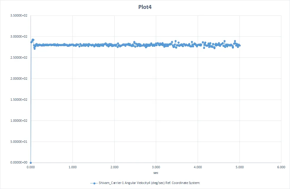
- As the torque is provided to sun gear, the angular velocity of carrier increases rapidly and there is small drop due to various components motion and gear sliding, after that it's almost constant with minor jerks in motion. The planet gears not only rotate about their axis but are also forced to roll on the inside of the ring gear since it is fixed. This results in low speed and high torque transmitting capacity.
- Case 2 -
- Input- Ring gear
- Output- Carrier arm
- Fixed- Sun gear
- Plot obtained from results of output-
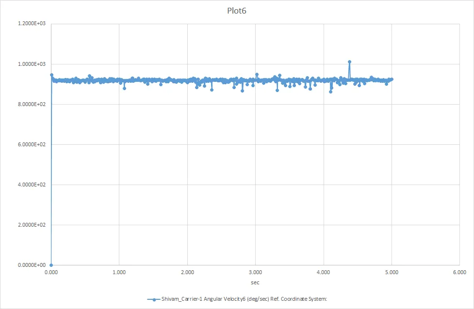
- Here also as the torque is provided to ring gear, the angular velocity of carrier increases rapidly and there is small drop due to various components motion and gear sliding, after that it's almost constant with minor jerks in motion. The angular velocity of carrier(output) is also quite large compared to other cases because of meshing of planet gears and ring gear which results in large gear ratios because of their geometry. This results in high speed and low torque transmitting capacity.
- Case 3 -
- Input- Sun gear
- Output- Ring gear
- Fixed- Carrier arm
- Plot obtained from results of output-
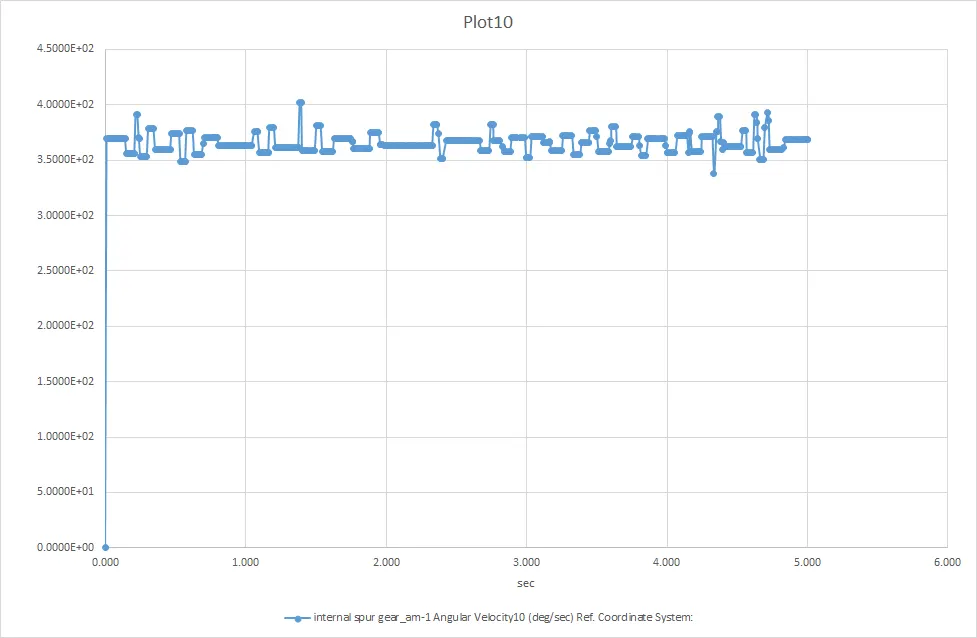
- The planet gears rotate only about their axis and transmit motion from sun to the ring and since the ring gear is large in diameter. This results in low speed and high torque transmitting capacity.
- The 3D model and assembly can be found from the following Google drive link : drive
- The link for the simulation of case 1 : link1
- The link for the simulation of case 2 : link2
- The link for the simulation of case 3 : link3
CONCLUSIONS : Planetary gears can be used in various mechanical systems due to it's dynamic natures, it can be used for low speed/high torque or high speed/low torque or any other desired ratios by fixing the known components.
REFERENCES :