Multi-body Dynamics: Planetary Gear
OBJECTIVE:
1. CALCULATION TO FIND OUT PLANETARY GEAR DIMENSIONS.
2. 3D MODELLING OF RING GEAR, PLANETARY GEAR, SUN GEAR AND CARRIER.
3. ASSEMBLY OF THE PLANETARY GEAR SYSTEM.
4. SETTING UP MOTION ANALYSIS.
5. PLOTTING OF ANGULAR VELOCITY OF THE OUTPUT FOLLOWING THE SAME:
| Sl.No | Input | Output | Fixed |
| 1 | Sun Gear | Carrier | Ring Gear |
| 2 | Ring Gear | Carrier | Sun Gear |
| 3 | Sun Gear | Ring Gear | Carrier |
6. SHARING LINK FOR THE ANIMATIONS
GIVEN DATA:
Use the following inputs for designing the Planetary Gear
- Ring Gear
- Module = 2.5 (You must use the metric system in design modeler)
- Number of teeth = 46
- Sun Gear
- Number of teeth = 14
- Input Speed of the Gear = 200 rpm.
- Number of planet gears = 4
The dimensions of the carrier depend on the shaft diameter of the planet gear.
- With the above input parameters, you are going to run a simulation on the following cases,
| Sl.No | Input | Output | Fixed |
| 1 | Sun Gear | Carrier | Ring Gear |
| 2 | Ring Gear | Carrier | Sun Gear |
| 3 | Sun Gear | Ring Gear | Carrier |
Hint:
- Input- Rotary Motion given to that part as input.
- Output- After motion analysis, Angular Velocity of that part is plotted as a graph.
- Fixed-Make that particular component as a fixed part.
- You should not use the Gear Mate.
- The module is the same for all the gears.
- You need to calculate the pitch circle diameter and the number of teeth for the planet gear.
THEORY:
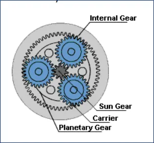
- An epicyclic gear train (also known as planetary gear) consists of two gears/more mounted so that the centre of one gear revolves around the centre of the other.
- A carrier connects the centres of the two gears/more and rotates to carry one gear, called the planet gear, around the other, called the sun gear.
- The planet and sun gears mesh so that their pitch circles roll without slip. A point on the pitch circle of the planet gear traces an epicycloid curve.
- The internal gear and planet gears mesh together now, such that their pitch circles roll without slip. THis internal gear is called ring gear.
CALCULATION:
Module (M) = Pitch circle diameter (PCD) / No. of teeth (N)
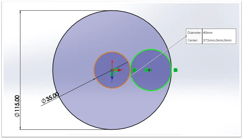
PCD, Ring = 2.5 x 46 = 115mm
PCD, Sun = 2.5 x 14 = 35mm
From the above 2D Modelling,
PCD, Planetary = 40mm
Thus, based on the formula:
N, Planetary = 40/2.5 = 16
SOLUTION:
1. PLANETARY GEAR DIMENSIONS:
- Pitch Circle Diameter = 40mm
- No. of teeth = 16
2. 3D MODELLING:
NOTES:
- For creating gear from Toolbox - go to design library - Toolbox - ANSI metric - Power transmission – Gears
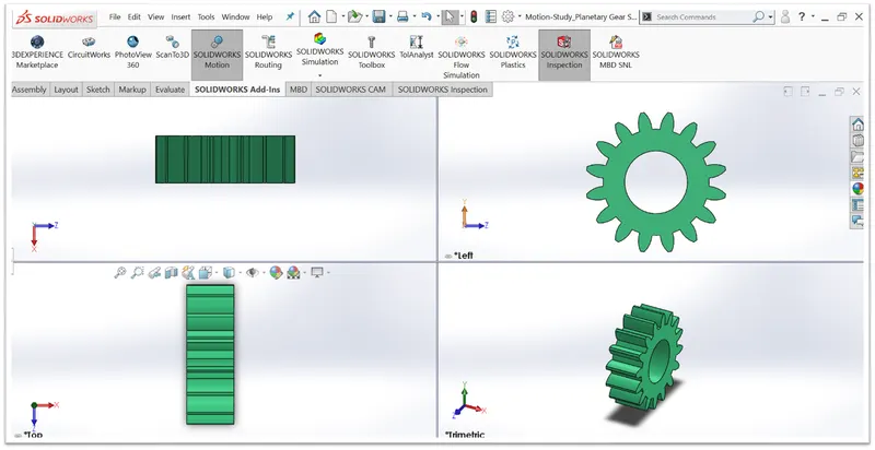
- For sun and planetary gears choose Spur gear
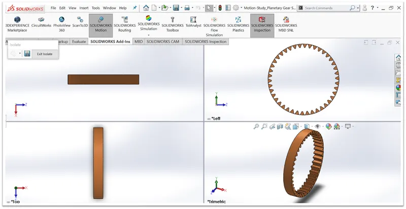
- For Ring gear to choose Internal Spur Gear
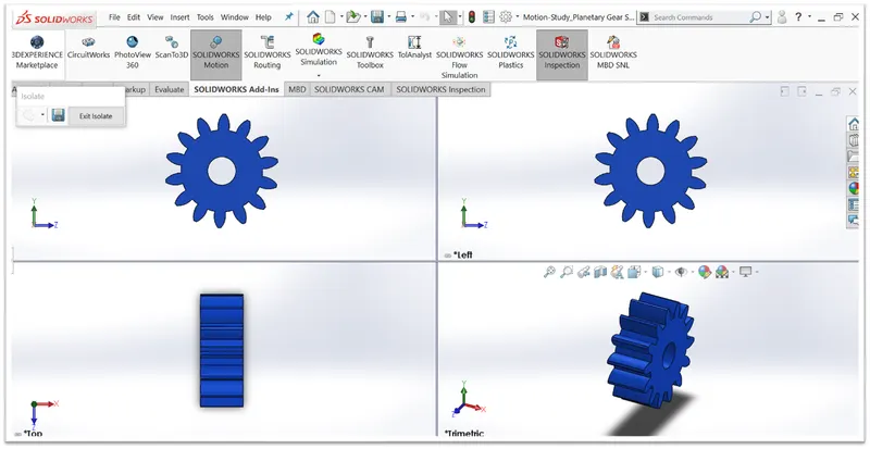
- By default, Module = 2.5, Pressure angle = 20, Face Width = 15 mm is same for all
- RING GEAR:
- PLANETARY GEAR:
- SUN GEAR:
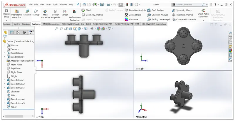
- CARRIER:
3. ASSEMBLY OF THE PLANETARY GEAR SYSTEM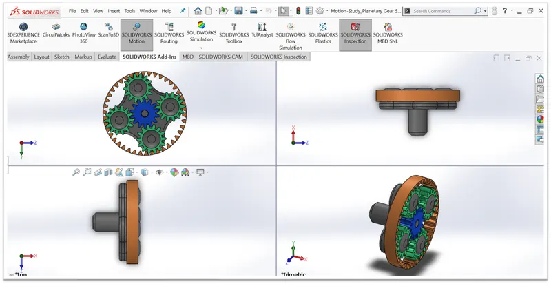
4. SETTING UP MOTION ANALYSIS:
- Motor is assigned to the SUN GEAR/RING GEAR as per the simulation to be carried out.
- Contact forces is now assigned next between the sun gear and planet gear-1, providing material as steel(dry) to both.
- Same process is carried out one-by-one to give contact force between sun gear and planet gear-2,3 and 4, giving same material properties to both.
- Next, contact force is given between the planet gear-1 and ring gear, keeping material properties same.
- Next, from the setting option, the frames are changed from 25 to 120 and precise contact option is enbaled.
5. PLOTTING OF ANGULAR VELOCITY:
NOTES:
- First, Force/Velocity/Displacement is selected.
- Next, Angular velocity is selected.
- Then, Magnitude is selected.
- Press Enter and see the plot.
- Rename from the bottom feature tree, if needed.
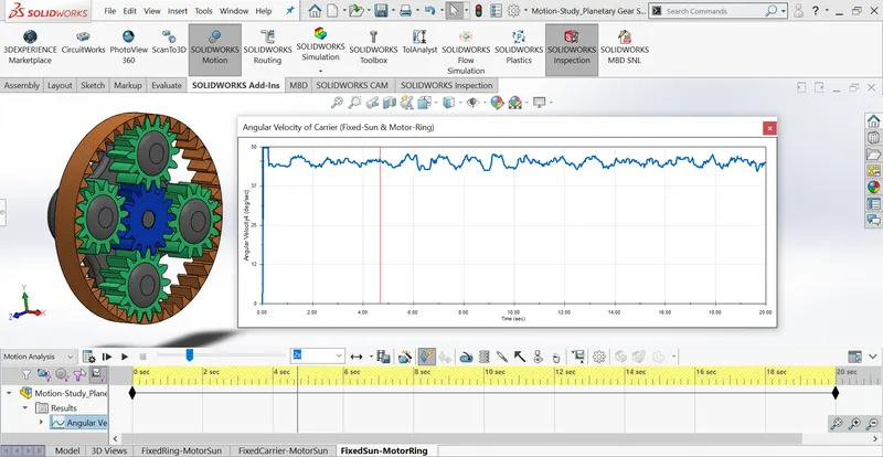
3 Different simulations are carried out and they are mentioned below with the plots.
- 1st: FIXED: SUN GEAR, MOTOR: RING GEAR, OUTPUT: CARRIER
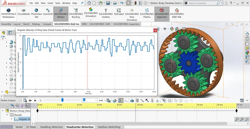
- 2nd: FIXED: PLANETARY GEAR, MOTOR: SUN GEAR, OUTPUT: RING GEAR
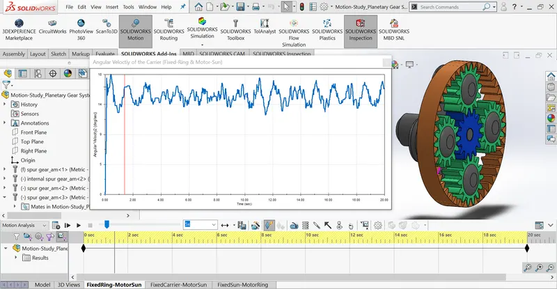
- 3rd: FIXED: RING GEAR, MOTOR: SUN GEAR, OUTPUT: PLANETARY GEAR
6. SHARING LINK FOR THE ANIMATIONS:
- 1st: FIXED: SUN GEAR, MOTOR: RING GEAR, OUTPUT: CARRIER
Link: INPUT: RING GEAR, OUTPUT: CARRIER, FIXED: SUN GEAR - 2nd: FIXED: PLANETARY GEAR, MOTOR: SUN GEAR, OUTPUT: RING GEAR
Link: INPUT: SUN GEAR, OUTPUT: RING GEAR, FIXED: CARRIER - 3rd: FIXED: RING GEAR, MOTOR: SUN GEAR, OUTPUT: PLANETARY GEAR
Link: INPUT: SUN, OUTPUT: CARRIER, FIXED: RING GEAR
CONCLUSION
- For making the graph more smoother we have used precise contact with 120 frames per second.
- In the first case, the carrier is fixed and output is to be obtained from the ring gear with the input given to Sun gear, all the gears rotate about their axis. The planet gears rotate only about their axis and transmit motion from sun to the ring and since the ring gear is big in diameter the angular velocity achieved is less. The deviations that are visible in the graphs show that there are points where sliding is occurring between the gears. The angular velocity obtained for this case is around 37-50 deg/sec.
- In the second case, when the input is given to the ring gear and output is obtained from the carrier keeping the sun gear fixed. The angular velocity achieved is maximum since the internal gear is big and planet gears are small comparatively so when a large gear meshes with a small gear the velocity achieved from the small gear is high because the velocity ratio is high. The angular velocity obtained for this case is between 12-25 deg/sec.
- In the third case, when the input is given to the sun gear and output is obtained at the carrier keeping the ring gear fixed, the planet gear not only rotates about their axis but are also forced to roll on the inside of the ring gear along with the carrier as the Ring gear is fixed. The angular velocity obtained for this case is between 12-15 deg/sec.