Planetary Gear
AIM-TO DESIGN AND SIMULATION OF PLANETARY GEAR
Software used is Solidworks
INTRODUCTION:
GEAR:
A gear is a rotating machine part having cut teeth, which mesh with another toothed part to transmit torque. The teeth on the two meshing gears all have the same shape. Two or more meshing gears, working in a sequence, are called a gear train or a transmission.
GEAR TERMINOLOGY:
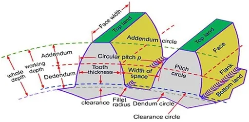
Gears are mainly identified by their module, pitch diameter, and no.of.teeth
For two Gears to Mesh they must have the same circle pitch ,same module and in order to have a constant angular velocity ratio for all positions of the wheel the pitch point must be a fixed point
Circle Pitch- It is the distance measured on the circumferrence of the pitch circle from a point of one tooth to the corresponding point on the next tooth
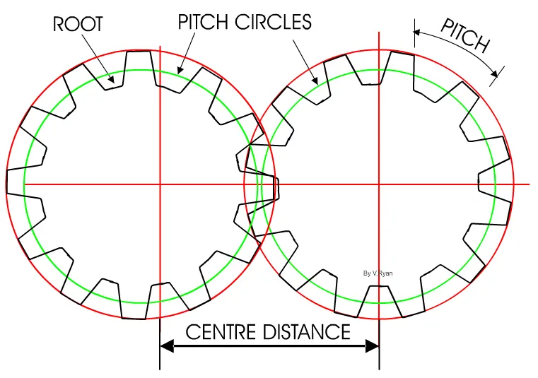
Module-It is the ratio between Pitch Circle Diameter and the number of teeth
m=D/T
PLANETARY GEARS:
A planetary gear consists of the sun gear, planetary gear, and ring gear which are connected to the carrier gear so that the center of one gear revolves around the center of the other. A carrier connects the centers of the planetary gears.
OBJECTIVE:
To design the planetary gears, by satisfying the following conditions :
- Ring Gear
- Module = 2.5
- Number of teeth = 46
- Sun Gear
- Number of teeth = 14
- Input Speed of the Gear = 200 rpm.
- Number of planet gears = 4
- The simulation and analysis will be done based on the following conditions;
CALCULATIONS
We have three parameters i.e. pitch circle diameter, module, and a number of teeth. The formula used to calculate the module ( if we know the pitch diameter and the no. of. teeth).
is given as;
m=d/T
Where:-
m = module
d = pitch diameter
T = number of teeth
CALCULATING PARAMETERS:
FOR RING GEAR:
m = 2.5 :T = 46 : d = ( value we need to find)
w.k.t., d=m⋅ T
d=2.5⋅46
d=115
FOR SUN GEAR:
Similarly, we can find out the pitch diameter for sun gear by using the formula.
d=35
FOR PLANET GEAR:
We need to find out pitch diameter and number of teeth. So we can find by the radius of sun and radius of inner gear (Radius of Ring Gear = Radius of Sun gear + Diameter of planet gear ).
[ 115 /2 = 35/2 + Diameter of planet gear ]
The diameter of planet gear: d=40.Now by using the main formula we can find out the number of teeth.
m=d *T => T=16 (Module is same for all the gears)
After calculating all unknown parameters the final result table is as follows.
|
Sr. No. |
Gear |
Pitch Circle Diameter |
Module |
Number of Teeth |
|
1. |
Ring Gear |
115 |
2.5 |
46 |
|
2. |
Sun Gear |
35 |
2.5 |
14 |
|
3. |
Planet Gear |
40 |
2.5 |
16 |
DESIGNING OF PARTS AND ASSEMBLY :
The design of parts can be done by selecting the toolbox and then importing the gears from ANSI(metric) in the Solidworks.
SUN GEAR:
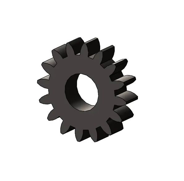
m=2.5, number of teeth=14, Pitch circle Diameter=35,Face Width=10,Nominal Shaft Diameter =17
[The nominal Shaft diameter is being used to design the carrier,All dimensions are in mm]

PLANET GEAR:
m=2.5 ,number of teeth =16,Pitch Circle Diameter=40,Face Width=10,Nominal Shaft Diameter=17
[The nominal Shaft diameter is being used to design the carrier,All dimensions are in mm]
RING GEAR:
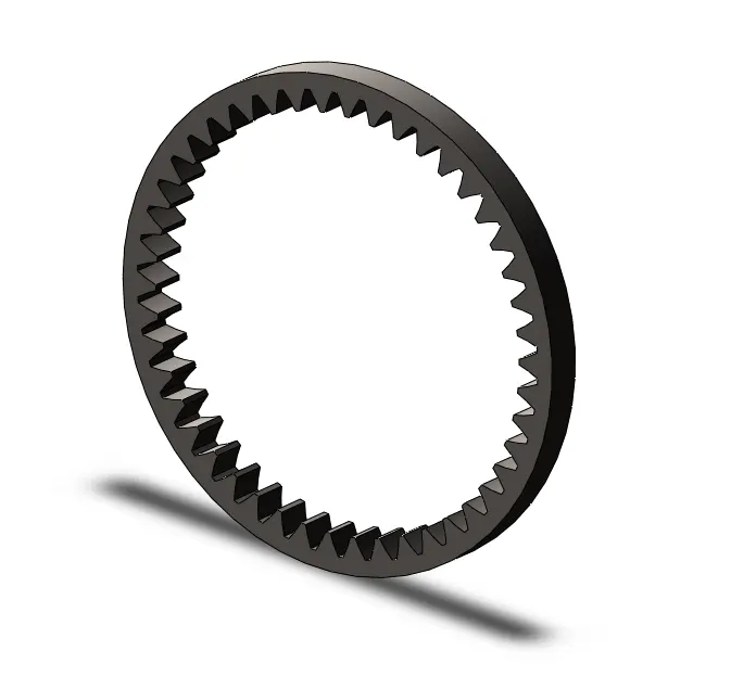
m=2.5 , number of teeth = 46,Pitch Circle Diameter=115,Face Width=10,Nominal Shaft Diameter=17
[The nominal Shaft diameter is being used to design the carrier,All dimensions are in mm]
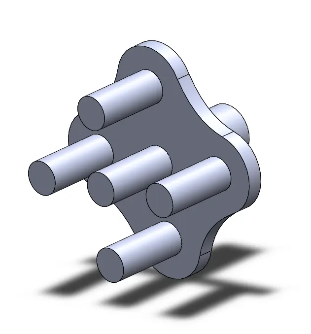
CARRIER
The carrier Dimensions are based upon the Nominal Shaft Diameter of the Gears
ASSEMBLY:
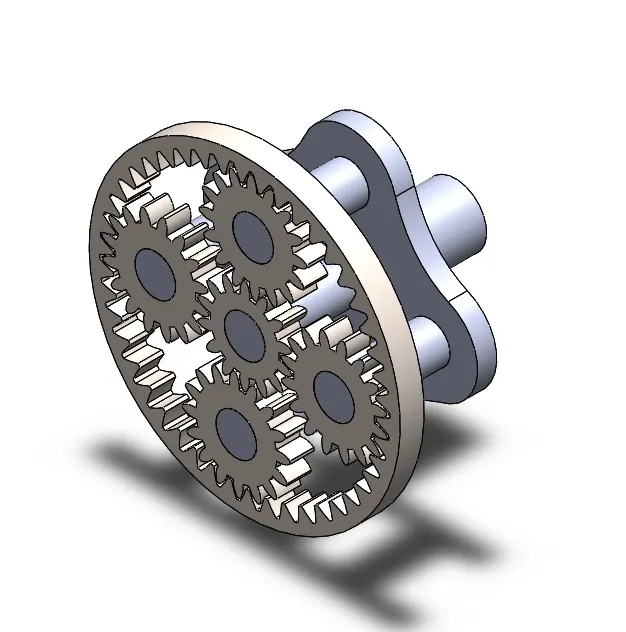
The assembly has been done by considering the condition “not to use gear mate” and the simulation is also done,First the carrier is being constrained so that the translation in X,Y,Z axis is constrained the only movement possible for this is rotation along X axis.
The Gears are being made concentric with the carrier and fixed so that they should also have only one degree of freedom i.e rotation.
Motion analysis
In the motion study make contacts between the followings.
- Carrier and the Planet gears
- Sun gear and the Planet gears
- Ring gear and the Planet gears
The material for each contact is Steel (Dry).
There are 3 cases
The input speed to the motor in each case is 200 RPM. The motion analysis is done for 20 seconds
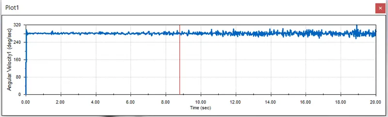
Case 1:
Ring gear fixed. Motor - sun gear.
The plot of an angular velocity of the carrier against time.
Case 2:
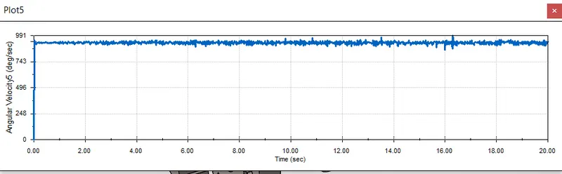
Sun gear fixed. Motor - Ring gear.
The plot of an angular velocity of the carrier against time.
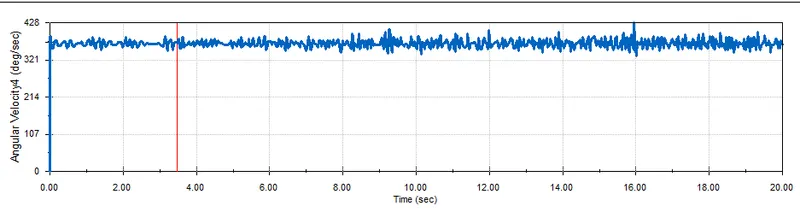
Case 3 :
Carrier fixed. Motor - Sun gear.
The plot of an angular velocity of the Ring against time.
Observation and conclusion :
- In the first case when the input is given to the sun gear and output is obtained at the carrier keeping the ring gear fixed, the planet gear not only rotates about their axis but are also forced to roll on the inside of the ring gear along with the carrier as the Ring gear is fixed. The angular velocity obtained for this case is between 240-320 deg/sec.
- In the second case when the input is given to the ring gear and output is obtained from the carrier keeping the sun gear fixed. The angular velocity achieved is maximum since the internal gear is big and planet gears are small comparatively so when a large gear meshes with a small gear the velocity achieved from the small gear is high because the velocity ratio is high. The angular velocity obtained for this case is between 743-991 deg/sec.
- In the third case the carrier is fixed and output is to be obtained from the ring gear with the input given to Sun gear, all the gears rotates about their axis. The planet gears rotate only about their axis and transmit motion from sun to the ring and since the ring gear is big in diameter the angular velocity achieved is less.The deviations that are visible in the graphs show that there are points where sliding is occurring between the gears. For making the graph more smoother we can use precise contact. The angular velocity obtained for this case is around 321-428 deg/sec.
Animation
Case 1-When Input is given to the Sun gear at 200rpm and the Ring Gear is fixed and output is obtained from the Carrier
Case 2-When input is Ring gear and Sun Gear is fixed and output is obtained from the Carrier
Case 3- Input is given to the Sun Gear and Carrier is fixed and output is obtained from the Ring gear
Google drive link for parts and assembly
https://drive.google.com/file/d/1W7lXY2-p2kDNmHHKPLkClyrz4aKVBGqv/view?usp=sharing
https://drive.google.com/file/d/1W7lXY2-p2kDNmHHKPLkClyrz4aKVBGqv/view?usp=sharing