Planetary Gear
AIM:
To use the given inputs and design planetary gears.
THEORY:
Basic Terminologies:
(i)Spur Gears: They type of gears whose teeth are cut parallel to the axis of the shaft.
(ii)Velocity Ratio: Velocity ratio is the ratio of the angular velocity of the driving gear to the angular velocity of the driven gear.
(iii)Pitch Surface: The pitch surfaces of the gears are imaginary planes, cylinders that roll together without slipping.
(iv)Pitch Circle: The pitch circle is the curve of intersection of the pitch surface of revolution and the plane of rotation. It is an imaginary circle that rolls without slipping with the pitch circle of the mating gear. The pitch circles of mating gears are tangent to each other.
(v)Pitch Circle Diameter: The pitch circle diameter is the diameter of the pitch circle. The size of the gear is usually specified by the pitch circle diameter.
(vi)Pressure Angle: The pressure angle is the angle which the line of action makes with the common tangent to the pitch circles. The pressure angle is also called the angle of obliquity. It is denoted by 'alpha'.
(vii)Circular pitch: The circular pitch (p) is the distance measured along the the pitch circle between two similar points on adjacent teeth. Therefore,
p= pi*d'/z
where d' = pitch circle diameter and z= no.of teeth
(viii)Diametral Pitch: The diametral pitch (P) is the ratio of number of teeth to pitch circle diameter.
P= z/d'
(ix) Module: The module (m) is defined as the inverse of the diametral pitch. Therefore,
m= 1/P = d'/z
PLANETARY GEARBOX:
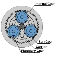
What is Planetary Gearbox?
A planetary gearbox is a gearbox with the input shaft and the output shaft aligned. A planetary gearbox is used to transfer the largest torque in the most compact form (known as torque density).
The bicycle’s acceleration hub is a great example of a planet-wheel mechanism: For a three-speed hub, a one-stage planetary gear system is used, for a five-speed hub a 2-stage. Each planet gear system has a reduction state, a direct coupling and an acceleration mode.
In mathematical terms, the smallest reduction ratio is 3: 1, the largest is 10: 1. At a ratio of less than 3, the sun gear becomes too big against the planet gears. At a ratio greater than 10 the sun wheel becomes too small and the torque will drop. The ratios are usually absolute i.e. an integer number.
The Arrangement
The most basic form of planetary gearing involves three sets of gears with different degrees of freedom. Planet gears rotate around axes that revolve around a sun gear, which spins in place. A ring gear binds the planets on the outside and is completely fixed. The concentricity of the planet grouping with the sun and ring gears means that the torque carries through a straight line. Many power trains are "comfortable" lined up straight, and the absence of offset shafts not only decreases space, it eliminates the need to redirect the power or relocate other components.
In a simple planetary setup, input power turns the sun gear at high speed. The planets, spaced around the central axis of rotation, mesh with the sun as well as the fixed ring gear, so they are forced to orbit as they roll. All the planets are mounted to a single rotating member, called a cage, arm, or carrier. As the planet carrier turns, it delivers low-speed, high-torque output.
A fixed component isn't always essential, though. In differential systems every member rotates. Planetary arrangements like this accommodate a single output driven by two inputs, or a single input driving two outputs. For example, the differential that drives the axle in an automobile is planetary bevel gearing – the wheel speeds represent two outputs, which must differ to handle corners. Bevel gear planetary systems operate along the same principle as parallel-shaft systems.
Even a simple planetary gear train has two inputs; an anchored ring gear represents a constant input of zero angular velocity.
Compound (as opposed to simple) planetary trains have at least two planet gears attached in line to the same shaft, rotating and orbiting at the same speed while meshing with different gears. Compounded planets can have different tooth numbers, as can the gears they mesh with. Having such options greatly expands the mechanical possibilities, and allows more reduction per stage. Compound planetary trains can easily be configured so the planet carrier shaft drives at high speed, while the reduction issues from the sun shaft, if the designer prefers this. Another thing about compound planetary systems: the planets can mesh with (and revolve around) both fixed and rotating external gears simultaneously, hence a ring gear is not essential.
Where is the Planetary gearbox generally used?
Where is the planetary gearbox usually used (in the transmission):
- In a robot to increase the torque
- In a printing press to reduce the speed of the rollers
- For precise positioning
- In a packaging machine for a reproducible products
Consider,
Ds= Pitch Circle Diameter of Sun Gear
Dr= Pitch Circle Diameter of Ring Gear
Dp= Pitch Circle Diameter of Planetary Gear
From Figure, we can say
Ds + 2Dp= Dr ...(i)
=> mTs + 2mTp = mTr .... (ii)
where m= module of gear
Ts= No. of teeth in Sun Gear
Tp= No. of teeth in Planetary Gear
Tr= No. of teeth in Ring Gear
Dividing equation (ii) by m, we get
Ts + 2Tp= Tr... (iii)
In this project we have to run motion analysis for three cases,
| Case | Input | Output | Fixed |
| 1. | Sun Gear | Carrier | Ring Gear |
| 2. | Ring Gear | Carrier | Sun Gear |
| 3. | Sun Gear | Ring Gear | Carrier |
CALCULATION:
Ring Gear:
module= 2.5
No. of teeth= 46
Therefore Pitch Circle Diameter (Dr)= 2.5 * 46= 115mm
Sun Gear:
module= 2.5
No.of teeth= 14
Therefore Pitch Circle Diameter (Ds) = 2.5 * 14= 35mm
Planetary Gear:
From Equation (iii), we know that
Ts + 2Tp = Tr
14 + 2Tp = 46
=> 2Tp= 32
=> Tp= 16
GEAR CONSTRUCTION:
Ring Gear:
Module: 2.5
No. of teeth: 46
Pitch Circle Diameter: 115mm
Face Width: 25mm
Outer Diameter: 140mm
Sun Gear:
Module: 2.5
No. of teeth: 14
Pitch Circle Diameter: 35mm
Face Width: 25mm
Internal Shaft Diameter: 20mm
Planetary Gear:
Module: 2.5
No. of teeth: 16
Pitch Circle Diameter: 40mm
Face Width: 25mm
Internal Shaft Diameter: 20mm
GEOMETRIC SETUP OF CARRIER:
1) Open Solidworks. Open a new part. Select the right plane and create a new sketch.
2) Draw a circle of radius 35mm. Coincide its center with origin.
3) Draw two construction lines perpendicular to each other which intersect at the origin. Draw another construction line which acts as the angular bisector to the previous two lines.
4) Draw a circle of diameter 40mm. Make it tangent to the 35mm circle and make its center lie on the 45deg line.
5) Mirror this circle horizontally and vertically such that there are 4 such circles surrounding the 35mm circle.
6) On the horizontal line, draw a circle of diameter 70mm and tangent to two 40mm circles. Mirror this circle on the other three sides. Trim the excess.
7) Exit sketch. Exrtude by 15mm. Select one face and sketch. Draw five circles of 20mm diameter, each concentric with the previous five circles. Exit sketch. The centre circle should be made into a hole of depth 10mm and the other 4 circles should be extruded by 25mm.
8) Select the other face of the pattern and sketch. Draw a circle of diameter 20mm with center at origin. Exit sketch and extrude it by 120mm. Carrier is ready.
ASSEMBLY:
1) Open a new assembly model. Export the carrier.
2) Coincide the right plane of the assembly with the right plane of the carrier. Coincide the front and top plane of the assembly with the central axis of the carrier.
3) Go to design library. Select standard as ANSI Metric. Select Power Transmission. Click on Gears. Under gears, select spur gears and click Insert into assembly. Make dimensions to that of planetary gears. Insert 4 such gears. Similarly repeat the same step and get sun gear and planetary gears.
4) Coincide the central axis of each planetary gear with the axis of each 25mm extrusion in the carrier. Then Coincide the front face of the planetary gear with the front face of the 25mm extrusion.
5) Coincide the center axis of the sun gear with the center axis of the carrier. Then coincide the front face of the sun gear with the front face of any planetary gear.
6) Coincide the central axis of the ring gear with the central axis of the carrier. Then coincide the front face of the ring gear with the front face of the planetary gear.
7) Go to the front view and move all the components till no two components overlaps with each other.
8) Assembly is complete.
MOTION ANALYSIS:
1) Right click the carrier and select float. Fix the ring gear.
2) Go to SolidWorks Add-Ins and select SolidWorks Motion. Go to the Motion Study. Change the type of motion study from Animation to Motion Analysis.
3) Select the motor option. Under reference face, select the inner circle of the sun gear. Make speed 200rpm.
4) Select Contact. Make it solid contact. Assume all components are made of Steel (Dry). Make contact between the sun gear and all planetary gears and between the planetary gears and the ring gear.
5) Calulate the Results. After calculation, select the results option and get the plot of angular velocity of the carrier.
6) Repeat the same steps for the other two cases.
RESULTS:
Case 1:
Input: Sun Gear
Output: Carrier
Fixed: Ring Gear
Video Link: https://www.youtube.com/watch?v=706SRlcyWQs&feature=youtu.be
Plot:
Case 2:
Input: Ring Gear
Output: Carrier
Fixed: Sun Gear
Video Link: https://www.youtube.com/watch?v=gIvkRq_ge0o&feature=youtu.be
Plot:
Case 3:
Input: Sun Gear
Output: Ring Gear
Fixed: Carrier
Video Link: https://www.youtube.com/watch?v=3-8Fg8LSdzE&feature=youtu.be
Plot:
INFERENCE:
(i) Case 1: Angular Velocity of the carrier reaches a peak value of 300 deg/sec, then dips a bit and then remains constant.
(ii) Case 2: Angular Velocity of the carrier reaches a peak value of 971 deg/sec, then dips a bit and then remains constant.
(iii) Case 3: Angular Velocity of the ring gear reaches a peak value of 382 deg/sec, then dips a bit and then remains constant.
REFERENCES:
https://www.sciencedirect.com/topics/engineering/epicyclic-gears