Flow over an airfoil
AIM:
To model the flow over a NACA0017 airfoil for the angle of attacks 0,2,4,6,8 and 10 degrees and compare their lift and drag forces.
THEORY:
An airfoil is the cross-sectional shape of a wing, blade(of a propeller,turbine and a rotor) or a sail. An airfoil-shaped body moving through a fluid produces an aerodynamic force. The component of this force perpendicular to the direction of motion is called lift. The component parallel to to the direction of motion is called drag. Subsonic flight airfoils have a characteristic shape with a rounded leading edge, followed by a sharp trailing-edge, often with a symmetric curvature of upper and lower surfaces. Foils of similar function designed with water as the working fluid are called hydrofoils.
Source:http://www.aerospaceweb.org/question/airfoils/q0100.shtml
The lift on an airfoil is primarily the result of its angle of attack. When oriented at a suitable angle, the airfoil deflects the oncoming air(for fixed-wing aircraft, a downward force), resulting in a force on the airfoil in a direction opposite to the deflection. This force is known as aerodynamic force and can be resolved into two components: lift and drag. Most foil shapes require a positive angle of attack to generate lift, but cambered airfoils can generate lift at zero angle of attack. This "turning" of air in the vicinity of the airfoil creates curved streamlines, resulting lower pressure on one side and higher pressure on the other. This pressure difference is accompanied by a velocity difference, via Bernoulli's principle, so the resulting flow field about the airfoil has a higher average velocity on the upper surface than on the other lower surface. The lift force can be directly related to the average top/botttom velocity difference without computing the pressure by using the concept of circulation and the Kutta-Joukowski theorem.
Source:http://www.aviationchief.com/angle-of-attack.html
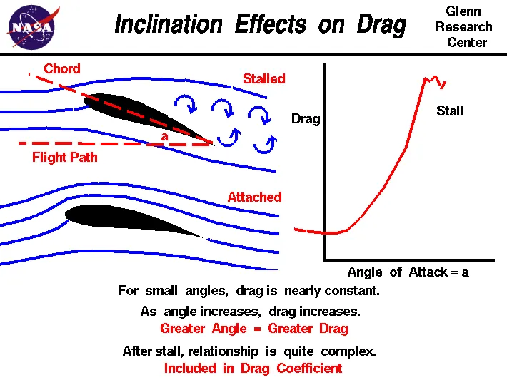
Source: https://www.grc.nasa.gov/www/k-12/airplane/inclind.html
PROCEDURE:
- Open SolidWorks and create a new document.
- Click Insert --->Curve ----> Curve through XYZ Points. A dialogue box opens.
- Click on Browse. Search for text file containing the coordinates of the airfoil. Click OK.
- Arrange the model in front view. Right click on the Front Plane and select Sketch.
- Select the Sketch and click on the Convert Entity option. It will turn black.
- If you zoom in, you will see that the airfoil is not closed. Select the line tool and draw a vertical line to close the sketch.
- Then click on the Rotate Entity options. Under entities to rotate, select the line and the spline. Select the centre of rotation as the point where the spline converges. Keep Rotation angle as 0 degree. Click enter.
- Exit the sketch. Under Features, click on Extrude. Extrude the sketch by 0.2m.
- Save the project. Open Flow Simulation and click on the Wizard option. Type a Project Name, SI System.
- The type of flow should be external and should be time-dependent. Total analysis time is 5 seconds and Output time step is 1 second.
- Working Fluid is air. The Velocity in X-direction is 600 m/s. The remaining properties can remain in their default values. Click Finish. The Computational Domain is created. Right click on the computational domain and click Edit. Change the settings from 3D Simulation to 2D Simulation(plane being XY Plane). Increase the limits of the domain. Click OK.
- Right Click Goals---> Insert Global Goals. Select Force (X), Force(Y), Frictional Force(X), Frictional Force(Y). Click Enter. Right click Goals again. Select Insert Surface Goals. Under Surface to be selected select the Extrusion. Under parameters, select Force(X) and Force(Y). Click Enter.
- Right click Mesh and select Show Basic Mesh. Right Click Mesh again and select "Insert Local Mesh". Under Surface to be selected, select the extrusion. These cells will be more refined. Click Enter.
- Run the program. The solver will open. Select Insert---> Preview. A dialogue box will open. Select Contours. The contour of the air foil will open. Click on Insert-->Goal Plot. Under the Parameters select SG Force(Y) (Lift Force).
- A graph wil appear. Many iterations will be taking place. Wait for the curve to flatten and an average value settles.
- Save the results and close the solver.
- Under Results, select Cut Plot. The Cut Plot dialouge box opens. Select the front plane. Click on Contour and choose velocity. Number of steps should be 15. Click enter. The cut plot is created.
- Now under Results, right click Goal Plots and select Insert. The Goals (Global and Surface) are shown asking which to be selected. Select SG Force X and SG Force Y and click Show.
- The Results tab opens, showing us the average values of SG Force X (Drag) and SG Force Y (Lift).
- Repeat the same steps for angles of attack 2,4,6,8 and 10 degrees.
RESULTS:
Case 1:For AOA= 0 degree
There will be fluctuations in the graph.
Drag Force: 302.477 N
Lift Force: -0.194N
Case 2: When AOA= 2 degrees
Drag Force: 401.840 N
Lift Force: 633.049N
Case 3: When AOA= 4 degrees
Drag Force: 497.849 N
Lift Force: 1492.702 N
Case 4: When AOA= 6 degrees
Drag Force: 622.658 N
Lift Force: 2347.311 N
Case 5: When AOA= 8 degrees
Drag Force: 734.619 N
Lift Force: 3267.393 N
Case 6: When AOA= 10 degrees
Drag Force: 989.540 N
Lift Force: 4218.312 N
REFERENCES:
http://www.aviationchief.com/angle-of-attack.html