Pipe flow simulation using solidworks
PIPE FLOW SIMULATION USING SOLIDWORKS
AIM:
- To Run a pipe flow simulation with an inlet Reynolds number of 100,1000 and 10,000.
- To Place line probes at 95%, 90%, and 85% of the pipe length.
- To Compare the normalized velocity profile at each of these locations
- Normalize the velocity profile by the inlet velocity.
WORKING:
- A thin pipe of length is simulated to carry fluid at three different velocities corresponding to Reynolds number 100, 1000, and 10000.
SPECIFICATIONS:
- Length of the pipe - 1m
- The diameter of the pipe - 20mm
- The thickness of the pipe - 1mm
PROPERTIES OF FLUID:
- Fluid - water
- Dynamic viscosity - 8.9*10^-4 Pa.s
- Density - 1000 kg.m^-3
FORMULA:
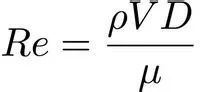
CALCULATE VELOCITY:
- Velocity = 0.00468421 m/s (For Re = 100)
- Velocity = 0.0468421 m/s (For Re = 1000)
- Velocity = 0.468421 m/s (For Re = 10000)
BOUNDARY CONDITIONS:
- Inlet velocity
- Static pressure at the outlet
- Real-wall of the pipe
RESULT AND PLOTS:
- To find the cut plot for the pipe at 85%, 90%, and 95% of the pipe length.
- To analyze the cut plot for different Reynolds numbers which tends to change in velocity as mentioned above.
- Plot the velocity range at the given length for different Reynolds numbers.
At Re = 100 (Cut plot of length 850mm, 900mm, and 950mm)
- At length 850mm
- At length 900mm
- At length 950mm
At Re = 100 (Velocity plot of length 850mm, 900mm, and 950mm)
- At length 850mm
- At length 900mm
- At length 950mm
At Re = 1000 (Cut plot of length 850mm, 900mm, and 950mm)
- At length 850mm
- At length 900mm
- At length 950mm
At Re = 1000 (Velocity plot of length 850mm, 900mm, and 950mm)
- At length 850mm
- At length 900mm
- At length 950mm
At Re = 10000 (Cut plot of length 850mm, 900mm, and 950mm)
- At length 850mm
- At length 900mm
- At length 950mm
At Re = 10000 (Velocity plot of length 850mm, 900mm, and 950mm)
- At length 850mm
- At length 900mm
- At length 950mm