Photo Realistic Rendering
1.REPORT ON ASSEMBLY OF CHOPPER MODEL
DESIGN OF AMERICAN CHOPPER USING SOLIDWORKS
OBJECTIVE
AMERICAN CHOPPER using a CAD software-SOLIDWORKS and to render it with SOLIDWORKS visualize to create a photorealistic view of it.
INTRODUCTION
This project explains the designing of American chopper using the CAD software SOLIDWORKS from sketching the parts and modelling them to final rendering of the assembly to give a photo realistic view.
METHODOLOGY
- Part Modelling
- Assembly
- Rendering
FLOW CHART
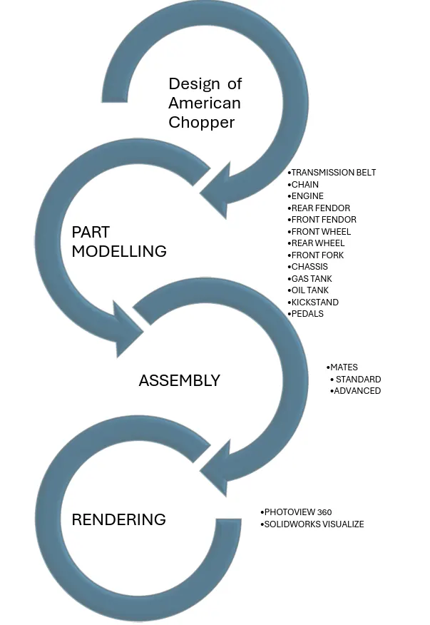
PART MODELLING
Step 1 -Start the new model.
Step 2- Sketching the outline using lines, circles , arcs, and other geometrical shapes using common tools in sketch.
Step 3 - Creating Feature using common feature like -Boss Extrude, Extrude cut, Revovled, Swept.
Step 4 - Refining the model using - Fillet,Chamfer, Shell, Patterns.
FEATURES USED
- Boss Extrude:
- This feature takes a closed profile sketch ( e.g. rectangle, circle) on plane.
- Extrudes the sktech along a specifeid depth and thickness to create 3D solid feature of 2D sketches.
- Extrude Cut:
- The Extrude Cut tool in SolidWorks is used to remove material from an existing solid model.
- It requires a closed profile sketch (like a circle, rectangle, or complex shape) to define the area to be cut.
- You specify the depth of the cut by setting a distance or using options like "Blind" (cuts all the way through) or "Up to Next" (cuts until it meets another face).
- Once applied, the Extrude Cut removes the specified material, resulting in a modified solid model with the desired cut-out feature.
- Revolve boss base:
- In SolidWorks, a Revolve Boss is a feature used to create a 3D solid by revolving a closed profile (sketch) around a chosen axis.
- This is ideal for creating axisymmetric features like cylinders, cones, or even more complex revolved shapes.
- By selecting a closed profile and an axis of revolution, the Revolve Boss tool adds material to part, resulting in a revolved solid feature.
- Revolve cut:
- The Revolve Cut feature in Solidworks is used to remove material from a solid model.
- It works by revolving a sketched profile around a chosen axis.
- Revolve cuts are useful for creating grooves, slots, channels, and other revolved features on 3D model.
- Lofted Boss/Base:
- Lofted Boss/Base is a powerful tool in SolidWorks used to create 3D solid models by connecting multiple 2D profiles.
- You start by sketching closed shapes (profiles) on planes in part. A minimum of two profiles is required, but more can be used for complex shapes.
- The Loft feature essentially "bridges" these profiles together, creating a smooth transition between them. Tool allows to optionally use guide curves to define the path the loft follows.
- The Loft can either add material (Boss) to create a solid form, or remove material (Base) from an existing solid.
- Swept Boss/Base:
- Creates a 3D solid by moving a closed 2D profile (like a circle or rectangle) along a path (straight or curved).
- Useful for creating pipes, tubes, channels, or other elongated shapes with varying profiles.
- Sweep cut:
- Creates a cut in 3D model by following a 2D profile along a path (straight line, arc, etc.).
- The path can be an edge, a curve, or even a set of curves.
- This flexibility allows for creating complex cut shapes.
- Tool allows to modify the profile or the path independently to achieve the desired cut geometry.
- Fillet:
- In Solidworks, the Fillet tool helps you transform sharp edges on 3D model into smooth, rounded corners.
- You define the radius size for the fillet. This allows you to create precise curvature for a desired aesthetic or functional purpose.
- Solidworks offers flexibility in selecting what to fillet. Tool allows to choose edges, faces, or even vertices (corner points) for the fillet application.
- Beyond the basic constant radius fillet, Solidworks provides options like variable radius fillets (gradually changing radius) and full round fillets (creating a complete cylinder or sphere at the corner).
- Chamfer:
- Chamfer creates a bevel on edges, faces, or vertices.
- It transforms a sharp corner on model into a sloped or angled edge, improving aesthetics and functionality.
- Tool allows to define the chamfer size with distance values or angles, and even control the chamfer direction for specific design needs.
- Split:
- It is a tool used to create new faces and reference lines on existing 3D models.
- It achieves this by splitting the model based on user-defined selections. There are three main methods for splitting: silhouette, projection, and intersection.
- Dome:
- This feature allows you to create a dome-shaped protrusion on an existing face of 3D model.
- Tool allows to define the size of the dome by specifying an expansion distance and optionally create a concave dome instead of the default convex shape.
- Shell:
- Shelling in Solidworks hollows out a solid part, leaving a thin-walled section.
- Tool allows to choose which faces to remove and specify the desired wall thickness.
- Solidworks Shell creates a lightweight model.
- Combine:
- Used to modify multiple existing solid bodies within a single part file.
- Combine allows to Add (merge), Subtract (remove material), or Find Common Area (intersection) of two or more solid bodies.
- Linear Pattern:
- A linear pattern replicates features or sketch entities in a straight line, allowing you to efficiently create repetitive features.
- Tool allows to define the pattern's direction using an edge or reference plane, and specify the spacing and number of copies to be created.
- Circular Pattern:
- Creates copies of a feature (extrusion, hole, etc.) in a circular pattern around a selected axis.
- This tool saves time and effort by replicating features instead of recreating them individually.
- It e nables creation of symmetrical or asymmetrical patterns.
- Mirror:
- Creates a symmetrical copy of selected features, faces, or bodies within a part or assembly.
- Creates a mirrored version within the same part file as a separate configuration.
- Or creates a completely new part file that is a mirrored copy of the original.
- Swept Surface:
- Creates complex shapes by sweeping a profile along a path.
- Extruding a 2D shape (profile) along a curved path to achieve a more intricate 3D form.
- This feature is ideal for modeling parts with non-linear features, such as pipes, blades, or sculpted objects.
- Tool allows to define the 2D profile using sketch tools and choose an existing curve or create a new path for the sweep operation.
- It is used to make a surface along with a path the curve is driven.
- Boundary Surface:
- The Boundary Surface tool in Solidworks lets you create free-form, curved surfaces. It's ideal for situations where a simple extrude or loft won't achieve the desired smooth curvature.
- Unlike Loft, Boundary Surface uses multiple curves (not just profiles) to define the surface. This allows for greater control over the shape and curvature in different directions.
- By enabling tangent or curvature continuity across the entire surface, Boundary Surface is often used to create high-quality surfaces for applications like consumer products or aesthetic designs
- Loft Surface:
- A loft feature generates a smooth surface by transitioning between two or more closed profiles (like sketched shapes) along a chosen path.
- The path defining the loft can be straight lines, curves, or even existing edges of other features in model.
- Loft surfaces are useful for creating complex shapes like pipes, turbine blades, or ergonomic product shells.
- Knit surface:
- The Knit Surface tool in Solidworks merges two or more adjacent surfaces into a single, unified surface.
- Surfaces must meet along their edges, not overlap each other, for a successful knit operation.
- Tool allows to choose to create a solid model if the knit surfaces enclose a volume, or simply keep it as a single surface entity.
- Surface Trim:
- Solidworks Surface Trim lets you cut away unwanted sections from existing surfaces using other surfaces, planes, or even sketches as trimming tools.
- Tool allows to choose between "Standard" trim, which uses a single entity for cutting, or "Mutual" trim, where multiple surfaces trim each other.
- During the trimming process, you decide what parts to retain. Tool allows to either choose to "Keep selections" (keeping specific surfaces) or "Remove selections" (discarding unwanted areas).
- Projection Curve:
-
A projection curve takes a 2D sketch (or another 3D sketch) and projects it onto a face, plane, edge, or another sketch in model. This essentially creates a new 3D curve that follows the path of the original sketch on the target surface.
-
Projection curves are handy for creating intricate 3D features that wouldn't be easily achievable with basic extrude or revolve commands.
-
Projected curves can be used as a base geometry for other operations like sweeps, where a profile is swept along the projected path to create a complex solid.
-
- Blocks:
-
In Solidworks, Blocks let you group together sketch entities (lines, circles, etc.) for reuse in other parts or drawings. This saves time by eliminating the need to redraw them each time.
-
Tool allows to save Blocks in a Design Library for easy access. This promotes consistency and simplifies collaboration on projects where multiple designers are involved.
-
While Blocks maintain their grouping, they can still be edited or exploded after insertion. This allows for adjustments to the geometry within the Block itself.
-
- Trim Entities:
- Modifies existing sketch geometry by cutting or extending entities based on selected references.
- Solidworks offers various trim methods like "Power Trim" for dragging across entities, "Trim to Closest" for automatic trimming to intersections, and others for specific trimming needs.
- Appearances:
- Appearances in Solidworks define the visual characteristics of a model, like color, texture, and material.
- They are applied to faces, features, bodies, or the entire part/assembly.
- Appearances add realism and clarity to 3D model, making it easier to visualize the final product and improve communication during the design process.
- Assembly:
- Open individual part files and insert them into the assembly workspace.
- Use mates (like coincident, parallel, etc.) to define the relationships and movement between parts.
- Apply joints (like hinges, sliders) to define allowed motion within the assembly.
- Check for assembly functionality, clearances, and potential interferences.
- ASSEMBLY APPROACHES IN SOLIDWORKS
- Top-Down Approach
- Bottom-Up Approach
- RENDERING
- Rendering in Solidworks transforms 3D model into a realistic or stylized image. It goes beyond the basic lines and adds details like materials, lighting, and shadows to create a visually compelling representation.
- This helps visualize the final product's look and feel, improving communication with clients, colleagues, or for marketing purposes.
- Solidworks offers PhotoView 360 for photorealistic renders, or Tool allows to leverage the built-in RealView Graphics for faster, simpler visualizations.
MAJOR CATEGORIES IN RENDERING
- Real-Time Rendering
- Pre-Rendering
SOFTWARE USED
- Photoview 360
- Solidworks Visualize.
COMPONENTS DESIGNED
- Transmission Belt
- Kick Stand
- Front Fender
- Rear Fender
- Chain
- Oil Tank
- Pedal
- Front Wheel
- Rear Wheel
- Front Fork
- Chassis
- Engine
- Gas Tank
DESCRIPTION
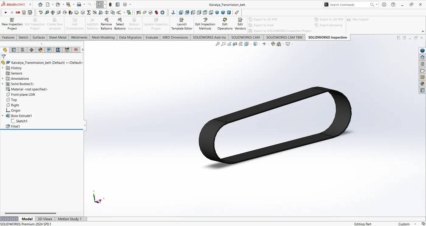
TRANSMISSION BELT
Features used
- Offset entities
- Extrude Boss/Base
- Fillet
- Appearances
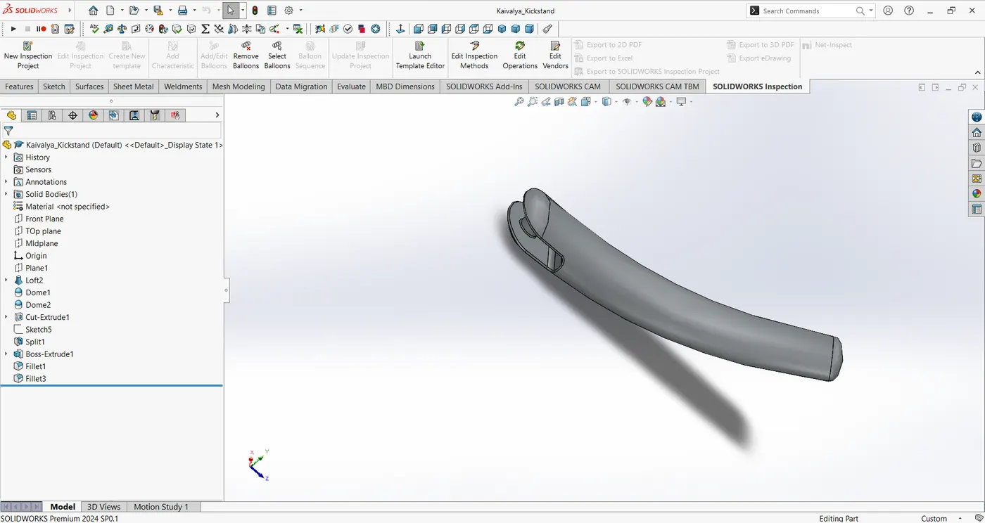
KICK STAND
Feature used
- Loft boss
- Extrude boss
- Extrude cut
- Dome
- Split
- Fillets
- Appearance
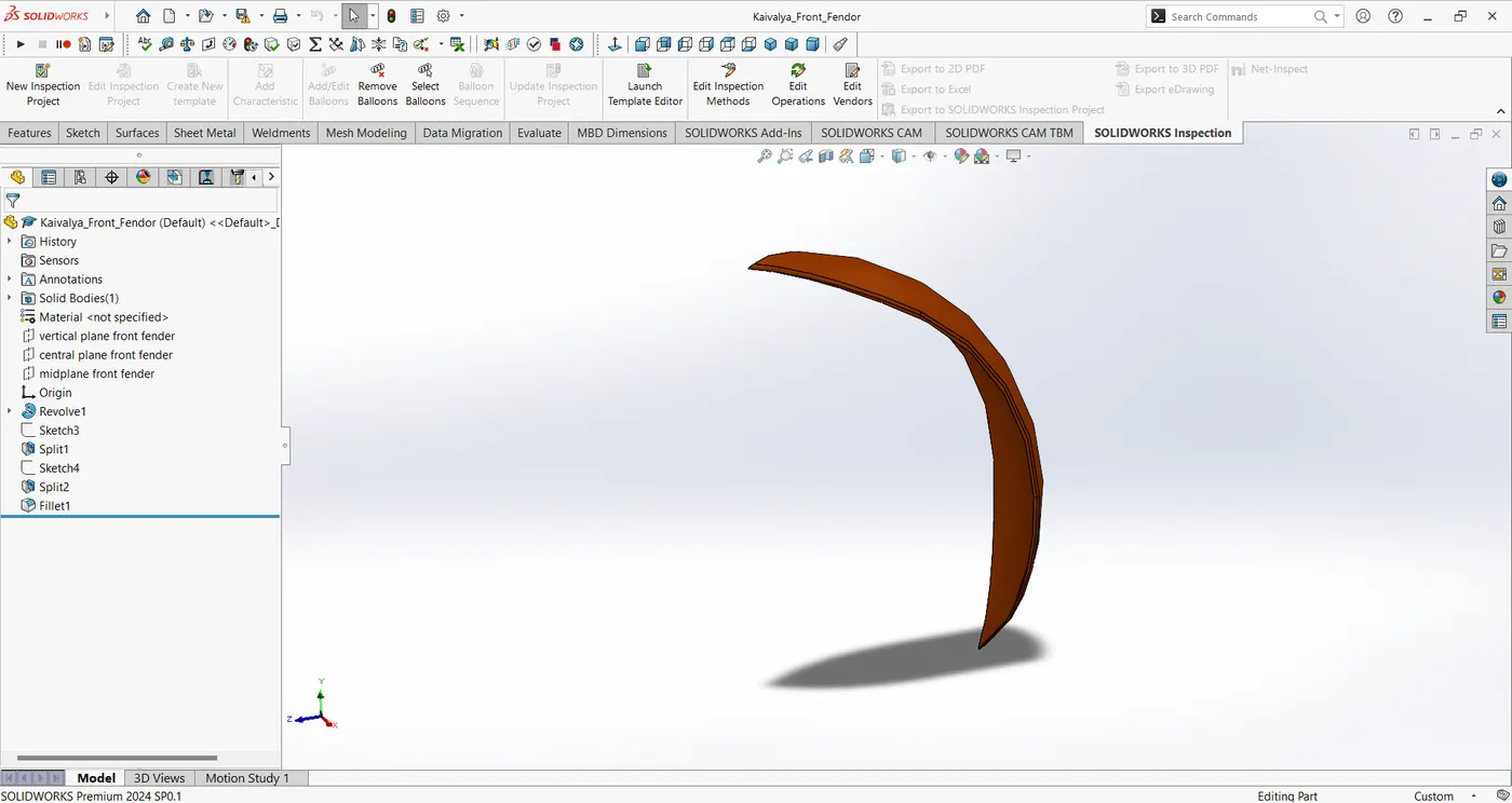
FRONT FENDER
Features used
- Offset entities
- Trim entities
- Revolve boss
- Dynamic Mirror
- Split
- Appearances
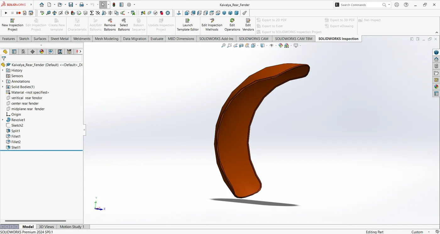
REAR FENDER
Features used
- Offset Entities
- Trim Entities
- Revolve boss
- Spilt
- Fillet
- Appearances
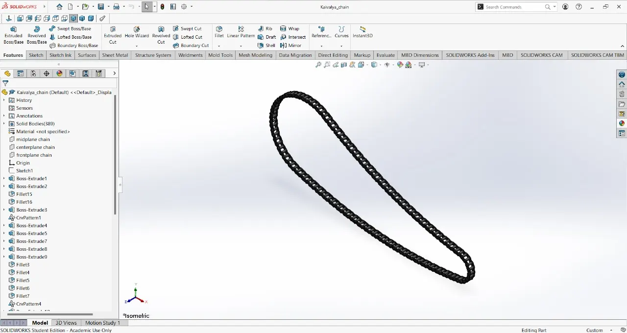
CHAIN
Features used
- Trim entities
- Fillet
- Blocks
- Extrude boss
- Linear Patterns
- Appearances
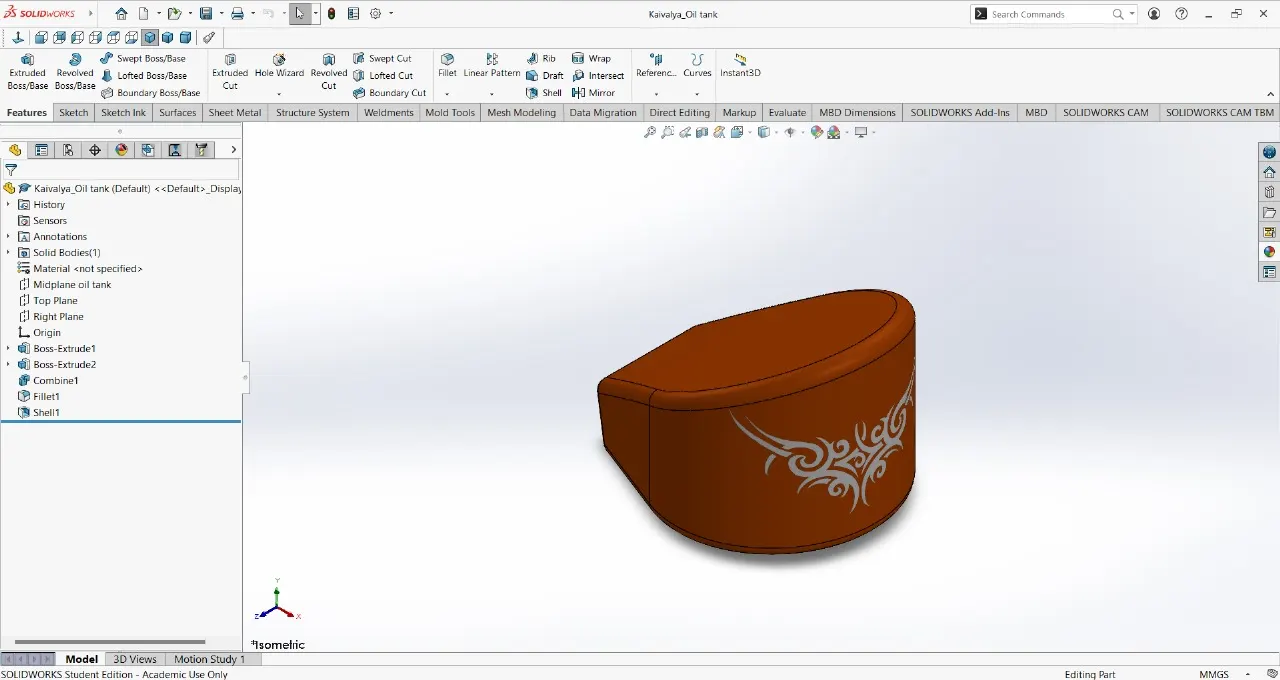
OIL TANK
Features used
- Boss Extrude
- Combine
- Fillet
- Shell
- Appearance
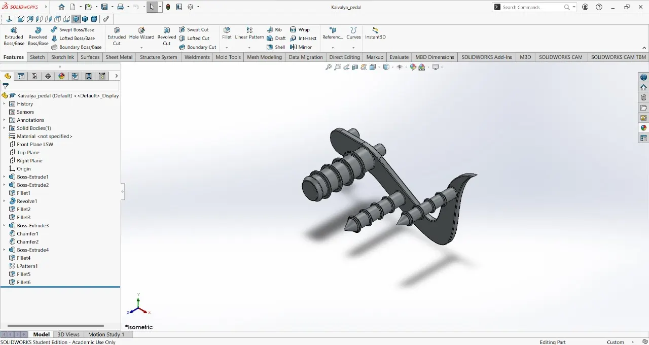
PEDAL
Features used
- Extrude boss
- Fillet
- Linear pattern
- Dome
- Chamfer
- Appearance
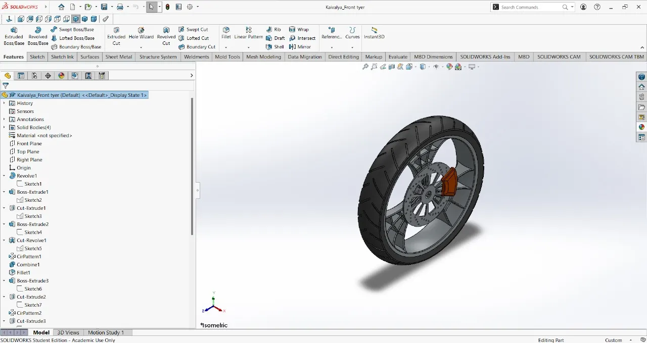
FRONT WHEEL
Features used
- Revolve boss
- Trim entities
- sketch fillet
- Boss Extrude
- Revolve Cut
- Linear Pattern
- Chamfer
- Cut Extrude
- Circular Pattern
- Appearance
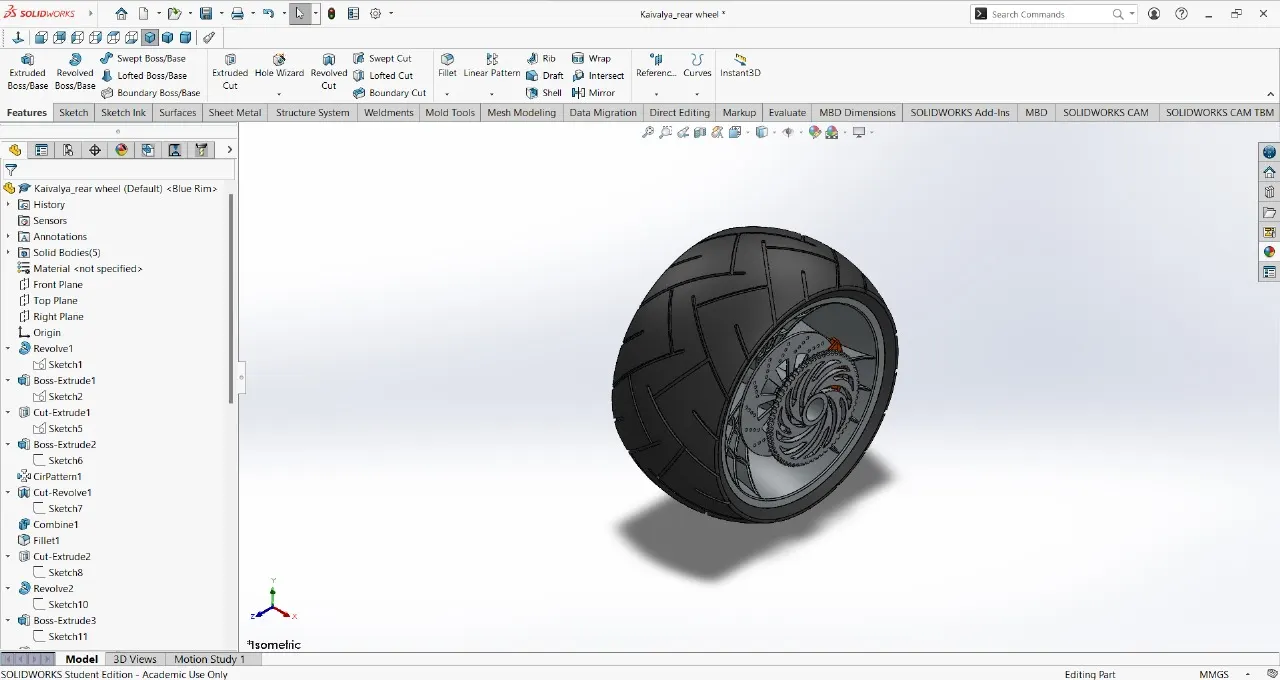
REAR WHEEL
Features used
- Revolve boss
- Trim entities
- Fillet
- Extrude Boss
- Planes
- Revolve cut
- Linear pattern
- Chamfer
- Fillet feature
- Extrude Cut
- Circular pattern
- Appearance
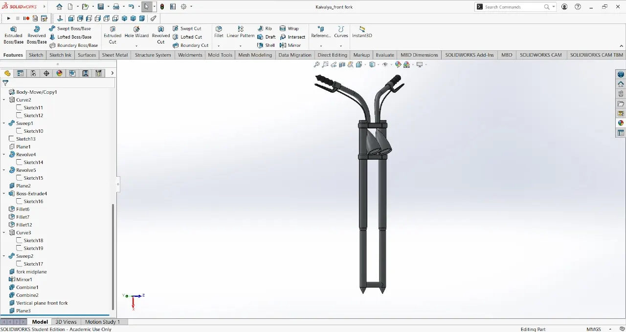
FRONT FORK
Features used
- Extrude boss
- Trim entities
- Revolve boss
- Split
- Move/copy bodies
- Dome
- Mirror
- Combine
- Projected curve
- Sweep boss
- Appearance
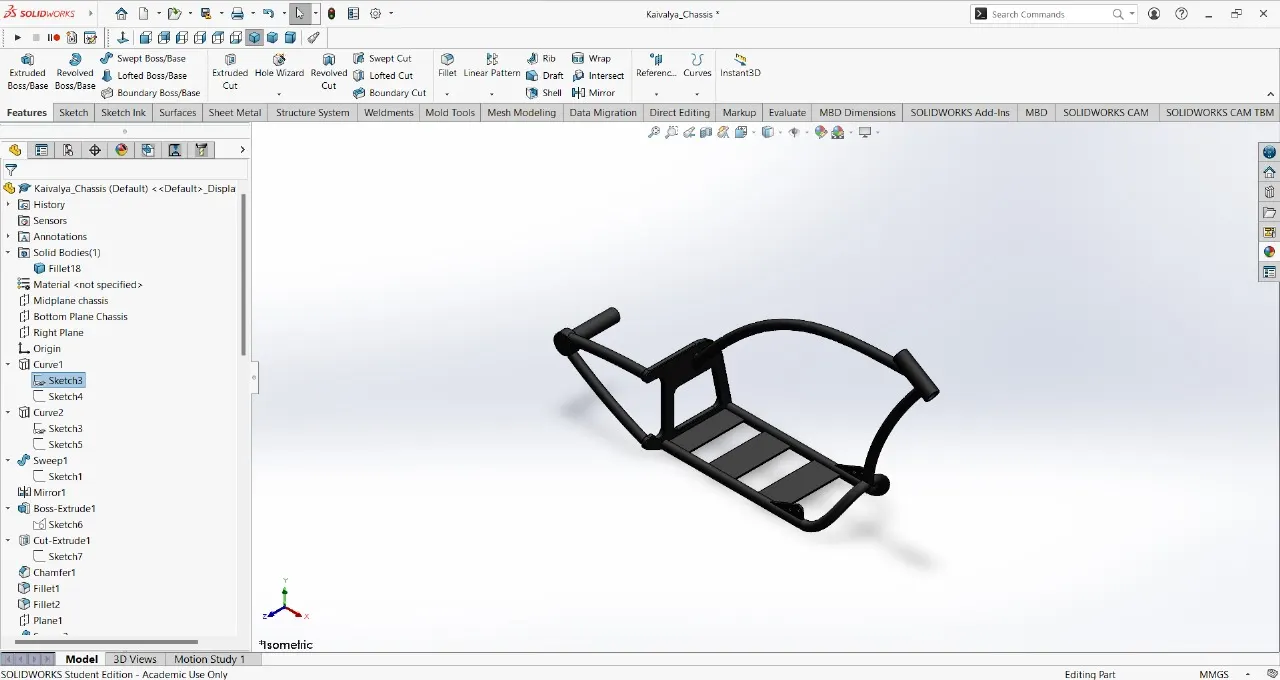
CHASSIS
Features used
- Offset entities
- Convert Entities
- Project Curve
- Trim entities
- Sweep boss
- Split
- Revolve Cut
- Extrude boss
- Fillet
- Combine
- Appearance
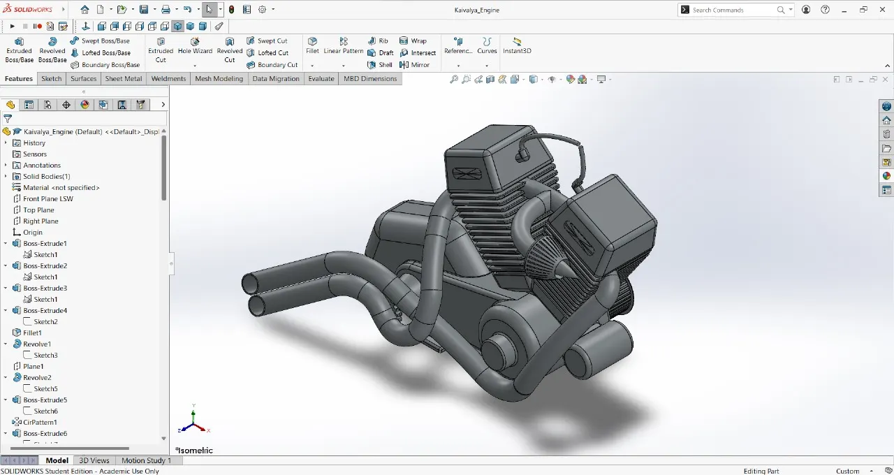
ENGINE
Features used
- Trim entities
- Revolve Boss
- Extrude Cut
- Offset entities
- Dome
- Fillet
- Projected Curve
- Composite Curve
- Sweep boss
- Mirror
- Circular pattern
- Split
- Appearance
GAS TANK
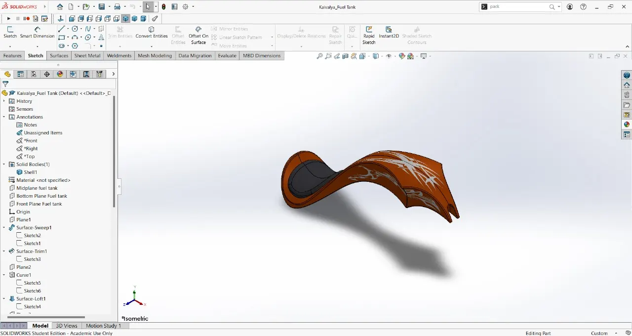
Features Used
- Projected curve
- Trim entities
- Sweep boss
- Loft surface
- Knit surface
- Sweep Cut
- Fillet
- Appearance
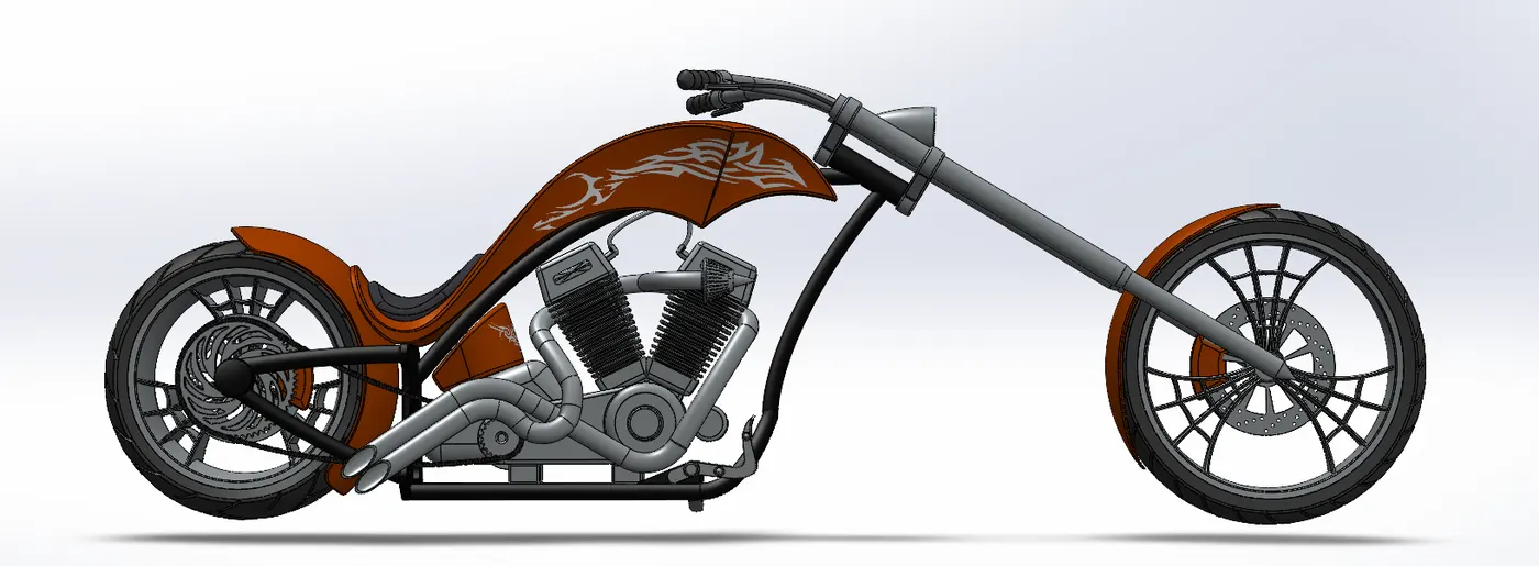
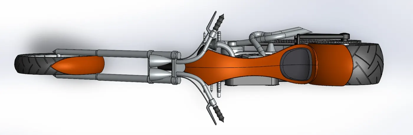
ASSEMBLED AMERICAN CHOPPER
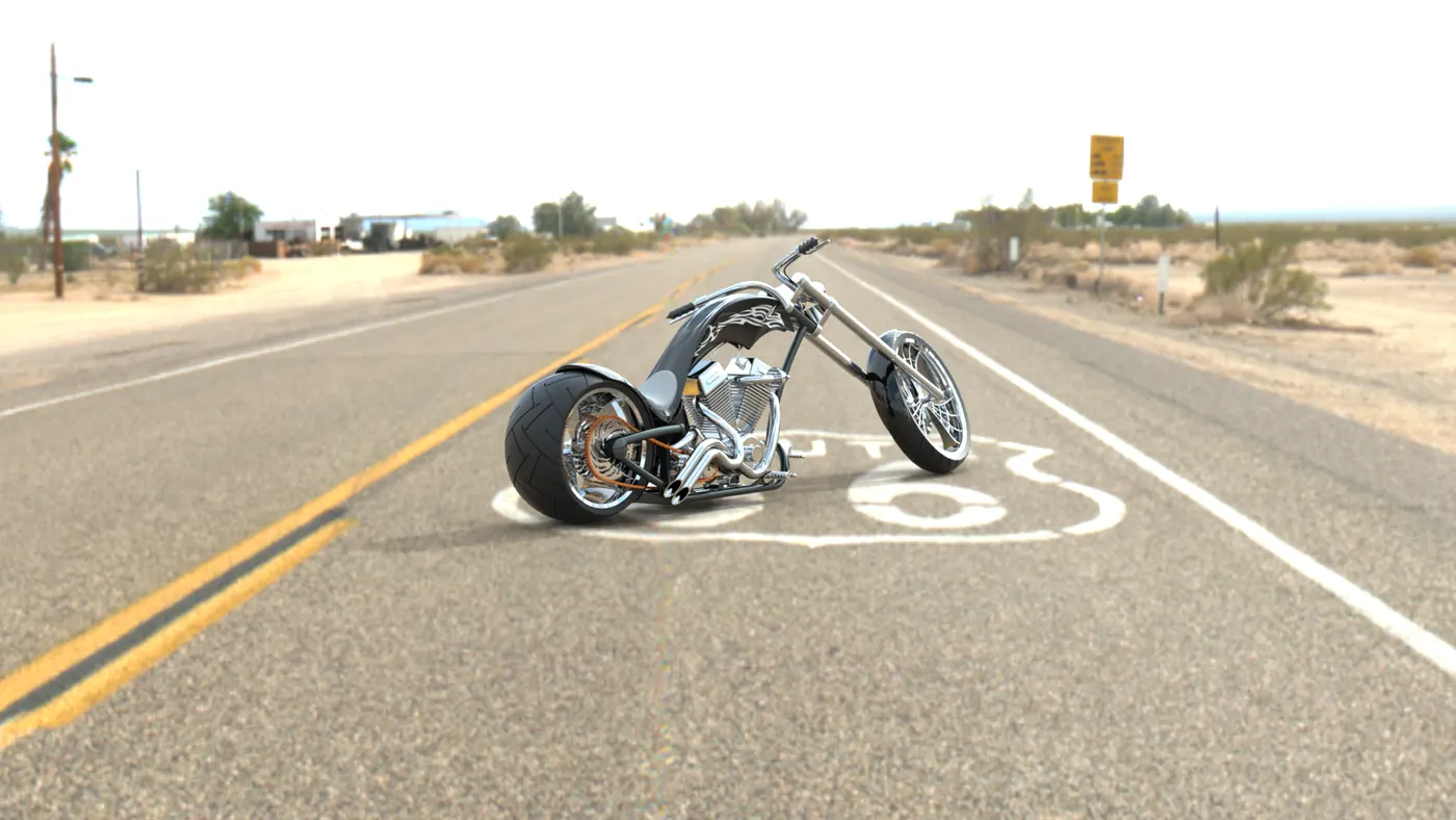
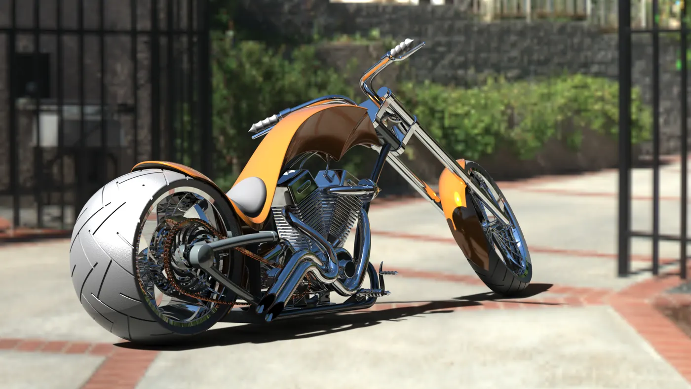
FINAL RENDERS OF AMERICAN CHOPPER
CONCLUSION
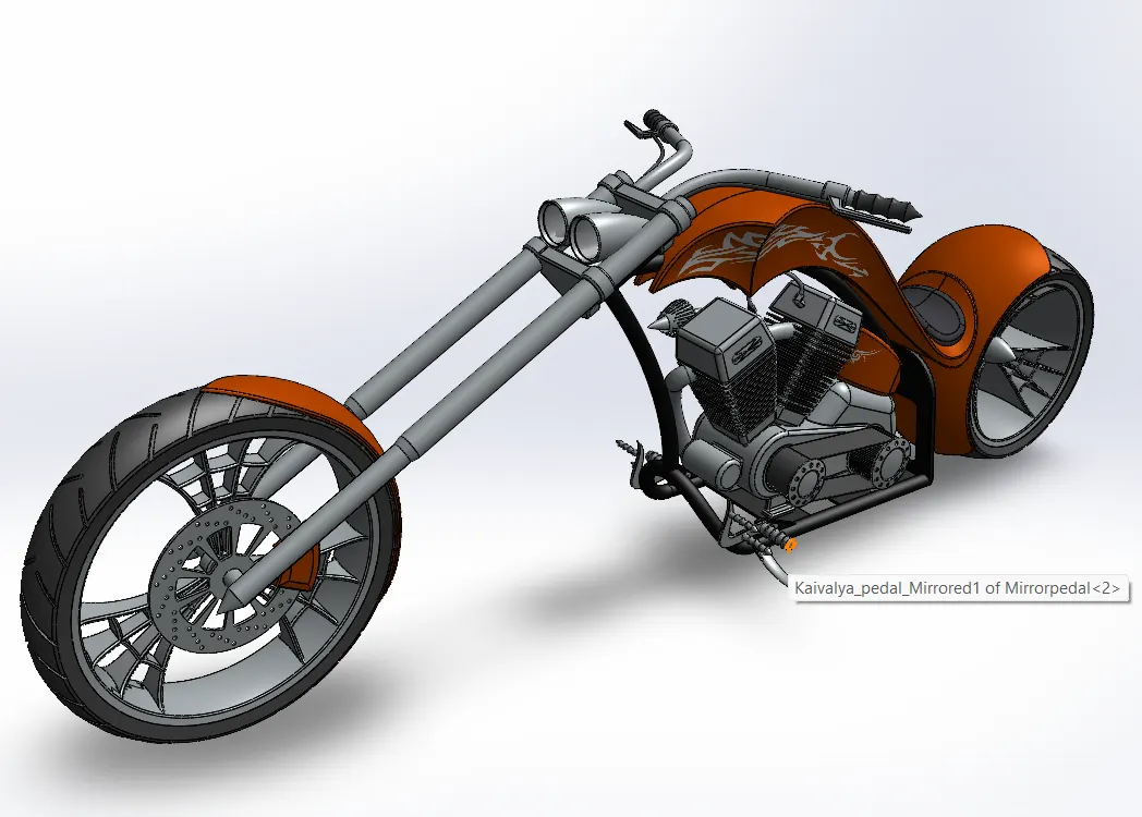
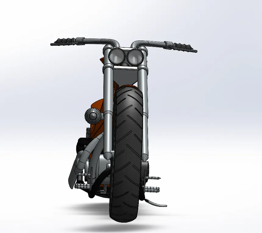
Thus, the parts of the AMERICAN CHOPPER are designed and assembled using SOLIDWORKS and are rendered to photorealistic images using PHOTOVIEW 360 and SOLIDWORKS VISUALIZE.
Attached linkis of drive which contenet all parts,assembly and rendered model zip file below due to large size of file .
https://drive.google.com/drive/folders/1ey6LJHnaq__pnbrJE48y7s682vvuyJ4H?usp=drive_link