Photo Realistic Rendering
MODELING OF AMERICAN CHOPPER IN SOLIDWORKS
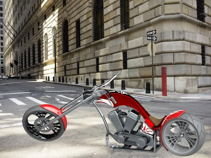
Objectives:
The main objectives of this project are:
- To create individual parts of the chopper using Solidworks
- To assemble all the individual parts into the chopper
- to know the application of decals, lights, cameras, etc
To create the photorealistic model and render it using Photoview 360 and Solidwork visualize
Introduction :
Solidworks is one of the prominent modeling software available today this software is mainly used to model 3D parts using 2D sketches. It also has the option to specify the material and look of the model which we created. It has other ADD-in features like photoview360 which helps in the rendering of the final model to make it look photo-realistic. In this project, we learned about the detailed design of Americal chopper parts and assembling them, and rendering the final after assembly.
Design methodology
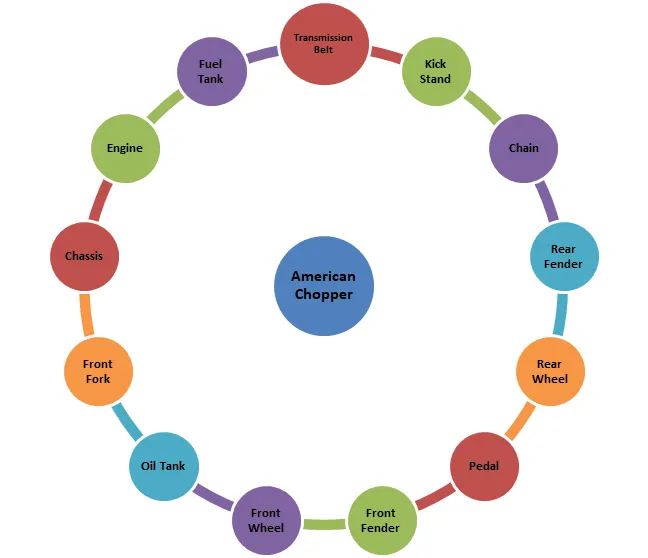
Details of Solidworks Features Used:
Sketch
The sketch is used to create the 2D representation of the model. In solid work, there are different entities available as follows:
- Line
- Circle
- Arc
- Spline
- Rectangle
- Polygon
- Fillet
- Ellipse
(Some sketch entities like line, circle, spline, arc, rectangle, etc. contain more options)
- Offset
The offset command create parallel line, curve, and concentric circles through a point or at a specified distance.
- Trim and extend entity
The trim command is used to remove the selected extra line/parts of an object. And the extend command is used to extend the selected boundaries or edges.
- Covert entity
It is used to project the last sketch into the current sketch plane.
- Mirror
The mirror is used to create the remaining half of a sketch/ copy of a selected sketch about a specified line.
- Linear sketch pattern
It is used to create multiple instances of features that can uniformly be specified along one or two linear paths.
- Smart dimension
It allows you to dimension the part which is created.
- Dynamic mirror
Select the dynamic mirror feature to mirror pre-existing sketch. First select the line, centerline, and linear model edge about which to mirror, and then create a sketch to mirror.
Path - Tool> Sketch Tools>Dynamic Mirror
Extruded boss/base:-
It is used to convert the 2D sketches into the 3D model in one or both directions from the sketch plane. Here you have to specify the direction up to the surface, vertex, value, and body from the sketch plane.
Extrude cut
It helps to remove material from the created 3D model by using the 2D sketch. It is the opposite of extruded boss/bass feature. Here also have to specify directions up to the surface, vertex, value, and body from the sketch plane.
Revolved boss/base:
It is used to revolve a 2D sketch (one or more profiles) along an axis, line, or centerline.
Revolved cut:
This feature is just the opposite of revolve boss/base. The revolved cut allows cutting a profile around an axis, plane, and line to create complex geometry.
Swept Boss/Base
A swept feature is used to create a solid body by moving a closed entity/ profile along a specified sketch/path. In order to complete a feature, two sketches are necessary. One will be the closed profile and the second will be the path.
Swept Cut
A swept cut feature allows cutting a 3D model by sweeping a closed sketch profile along a specified path sketch. The path sketch will control the direction of the cut. Profile sketch should be connected to the path sketch.
Lofted boss/base
The loft feature creates a solid body by making the transition between multiple profiles and guide curves. It helps to generate complex geometry in one feature.
Lofted cut
The loft cut is allowed to remove the material between two sketch profiles. Make sure that selections are must under the profile selection box and not the guide curve selection box
Fillet
It is used to create a rounded shape at the internal or external faces of the part. There are different types of fillets:
- Constant Size fillet
- Multiple radius fillet
- Round corner fillet
- Setback fillet
- Variable size fillet
- Face fillet
- Full round fillet
- Asymmetric fillet
Chamfer
This feature creates a cut on a selected edge, face, or vertex. Types of chamfer:-
- Angle –Distance- Enter the values of distance and angle in the chamfer parameter box.
- Distance- Distance- Enter the values for both distances in the chamfer parameter box or on the side of selected edges.
- A vertex- Enter values for the three distances on each side of the selected vertex.
Patterns
- Linear pattern – To create multiple instances of one or more features that can space uniformly along a specified path, or plane.
- Circular pattern – To create multiple instances of one or more features that can space uniformly along an axis, or line.
- Curve Driven Pattern – To Curve creates multiple instances of one or more features that can space uniformly along the 3D curve (open or closed curve).
Shell
It is used to define the thickness of a wall, hollow out a part, and leave open the selected faces. Shell may be with uniform or multiple-thickness faces.
Dome
Dome features are used for one or more domes on the same model in one feature.
- Face to the dome - Used to apply dome to faces whose centroid lies outside the face.
- Elliptical Dome -Used to apply dome for cylindrical/ conical model.
Path- Insert>Feature>Dome
Split
The split feature is used to create multiple bodies or surfaces from one part/ surface. In the small toolbox, we must select Sketch and click on cut part. With this feature, we can create multiple bodies or consume cut bodies.
Path- Insert>Feature>Split
Combine
There are three different options available to use the combined feature.
- Add-To merge multiple bodies together into one.
- Subtract-To remove multiple bodies from the main body.
- Common- To add two bodies together and keep the area that is common to them.
Path- Insert>Feature>Combine
Feature description for surface Modelling:
Surface modeling is used to build out a representation of solid objects exterior and it’s a contour. The following feature is used in the design of the seat, and gas tank of the chopper.
Swept Surface
The surface is created by a sweep profile and sweep path.
Lofted Surface
The surfaces are generated by multiple 3D curves / existing edges. There should be a tangency between the selected curve/edges.
Boundary Surface
The boundary surface creates surfaces that can be tangent or curvature continuous in both directions. In most cases, we get high-quality results as compared to lofted surfaces.
Filled Surface
The feature creates a surface to fill the gap in a model.
Surface Trim
It is used to cut away material from a surface.
Extend Surface
This feature extends the surface by selecting an edge, multiple edges, or a face.
Surface Knit
The surface knit feature combines multiple faces and surfaces into one. Surface edges must be adjacent and not overlapping.
Appearance
An appearance is defined as the visual properties of the model which include color and texture. We can apply appearance to the individual to the complete model / one or more faces/edges. It does not affect physical properties which are defined by material.
Description of American chopper parts and used features in detail:-
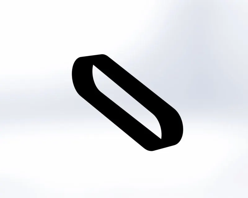
1. Transmission Belt:-
It is made up of flexible material and used to transmit power efficiently from a motor to the drive shaft/ pulley or to track relative movement. Sometimes it’s called drive belts, gear belts, or automotive belts.
Features used to create Transmission belt:
- Rename the Planes:-
Front Plane – Front Plane of Transmission Belt
Top Plane- Top Plane of Transmission Belt
Right Plane-Right Plane of Transmission Belt
- Sketch
- Offset
- Extrude Boss/Base
- Fillet
- Appearance :- Matte Rubber
- Save the part- Transmission Belt
Note- All used features are explained above.
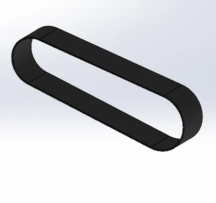
Transmission Belt
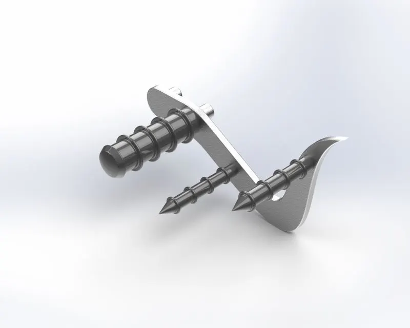
2. Kickstand:-
A kickstand is a supporting structure provided to a bike that flips down from the frame and makes contact with the ground when stationary. It is also known as a side stand.
Features used to create kickstand-
- Rename the Planes:-
Front Plane – Front Plane of the Kickstand
Top Plane- Top Plane of the Kickstand
Right Plane-Mid Plane of Kickstand
- Sketch
- New Plane
- Loft Boss/base
- Dome
- Extrude Cut
- Extrude Boss/Base
- Split
- Fillet
- Appearance:- Chrome
- Save the part- Kickstand
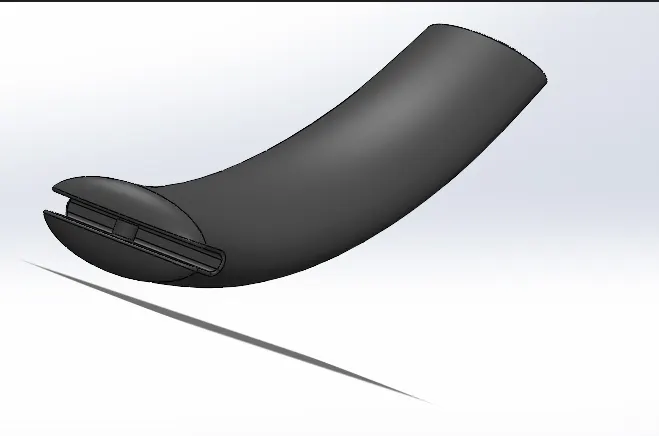
Kickstand
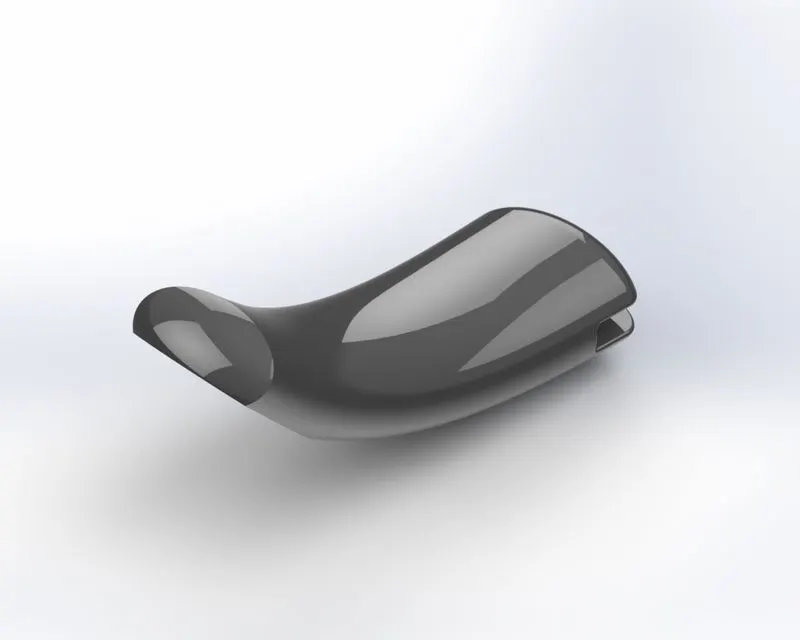
3. Front fender:-
The Front fender is an automobile part mounted on the fork above the wheel. Its purpose is to protect riders and bicycles from mud, sand, or liquids.
Features used to create front fender-
- Sketch
- Revolve
- Sketch with dynamic entity
- Split
- Fillet
- Appearance -Siena
- Save the part model- Front fender
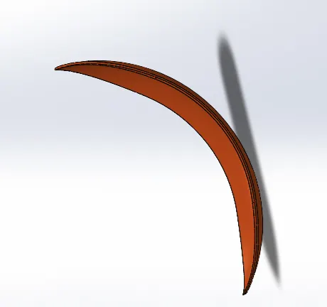
Fig.3 Front Fender
4. Rear fender:-
The application of the rear fender is the same as the front fender. The rear fender is mounted on the rear part of the chassis and above the rear wheel.
Features used to create rear fender
- Sketch
- Revolve
- Sketch with dynamic entity
- Split
- Fillet
- Shell
- Appearance- Siena
- Save the part- Rear Fender
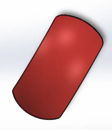
Fig. 4 Rear Fender
5. Oil Tank:-
The oil tank is used to store the lubricating oil which is required to run the engine. Oil is generally used to avoid wear and tear due to extreme heat. It is hollow from the inside.
Features used to create oil tank -
- Rename the plane-
Front plane- Midplane of Oil Tank
- Sketch
- Extrude Boss/Base
- Combine
- Fillet
- Shell
- Appearance- Siena
- Save the part- Oil Tank
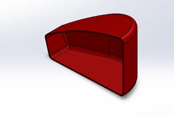
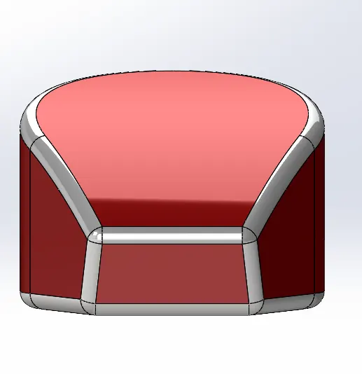
5 Oil Tank
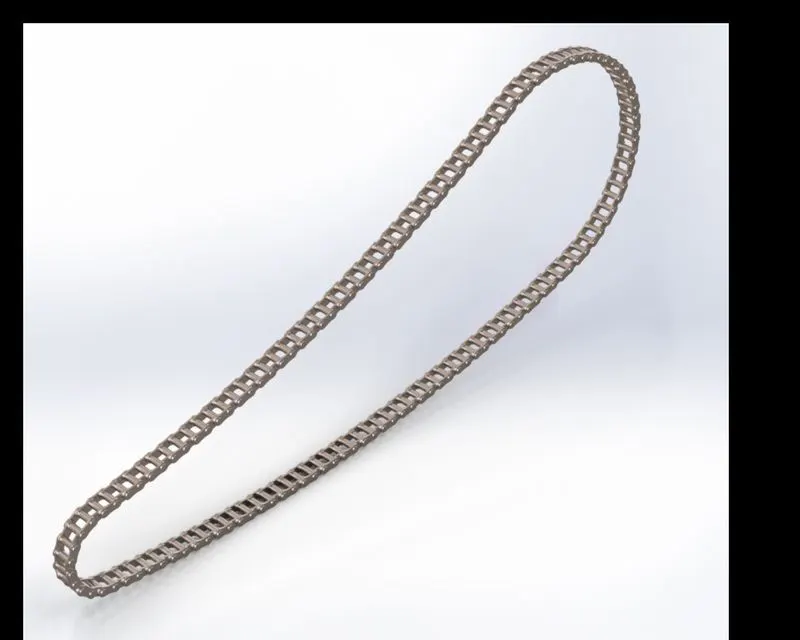
6. CHAIN:-
Chains are used as part of the drive train to transmit the motor power to the back wheel.
The feature used to create chain-
- Rename the planes-
Front Plane- Mid Plane of Chain
Top Plane- Center Plane of Chain
Right Plane- Front Plane of Chain
- Sketch
- Sketch Block
- Extrude Boss/Bass
- Fillet
- Curve Driven Pattern
- Solid Body Folder
- Mirror
- Appearance- Carbon Steel
- Save the Part- Chain
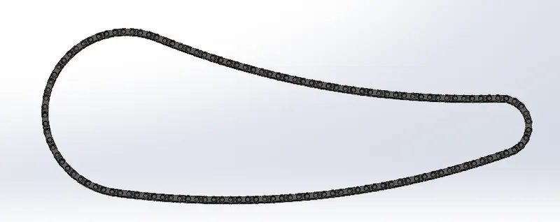
6 Chain
7. Pedal:-
The pedal is the part of a chopper and it is used to rest the leg on top of that.
Features used to create pedal-
- Sketch
- Extrude Boss/Base
- Revolve
- Dome
- Chamfer- Distance –Distance
- Fillet
- Linear pattern
- Appearance- Chrome steel
- Save the part -Pedal
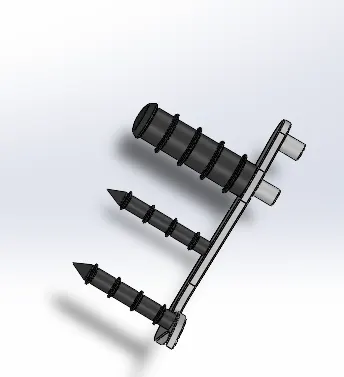
7 Pedal
8. Front wheel:-
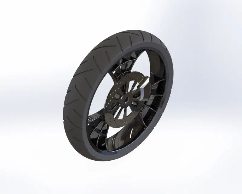
The front wheel is a rolling part of the chopper situated on the front side. The part guides the vehicle as per the movement of the front fork. The wheel contains – Caliper, Rim, Rotor, and tire. At the outer side of the wheel, the rubber material is attached called a tire.
Features used to create front wheel-
- Sketch
- Revolve Boss/bass
- Extrude Boss/base
- Extrude cut
- Intersection entity.
- Revolved Cut
- Circular pattern
- Combine
- Fillet
- Chamfer
- Appearance-
Rim- Chromium Plate
Rotor- Carbon steel
Caliper- Siena
Tire-Matte Rubber
- Save the part- Front Wheel
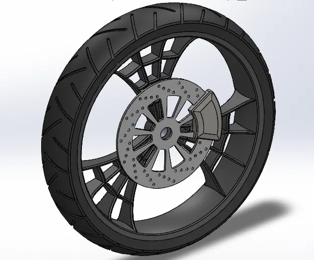
8 Front Wheel
9. Rear Wheel:-
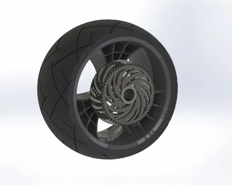
The rear wheel is a rolling part of the chopper situated on the rear side. The part revolves around an axle. The wheel contains – Caliper, Rim, Rotor, Disc, Sprocket, and tire. The chain is connected between the engine and the sprocket of the rear wheel.
Features used to create rear wheel-
- Sketch
- Revolve Boss/Base
- Extrude Boss/base
- Extrude cut
- Intersection entity
- Revolved Cut
- Circular pattern
- Combine
- Fillet
- Chamfer
- Appearance-
Rim- Chromium Plate
Rotor- Carbon steel
Caliper- Siena
Sprocket- Chromium Plate
Tire-Matte Rubber
- Save the part- Rear Wheel
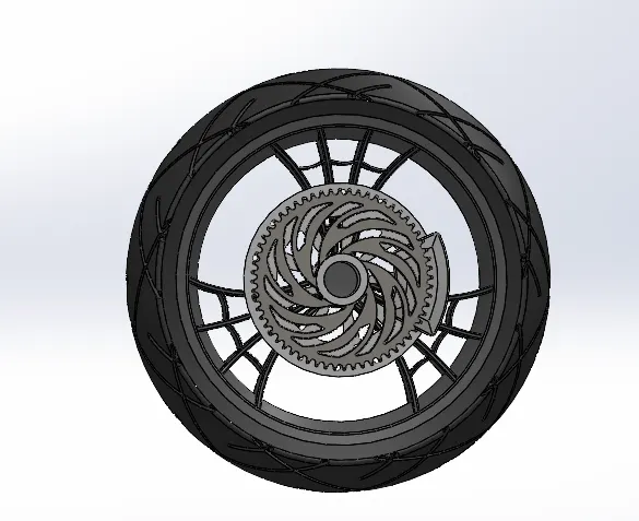
9 Rear Wheel
10. Front fork:-
A chopper fork connects a front wheel and axle to its chassis. It guides the complete vehicle. Fork contains – Handles, brakes, axle, lights, etc.
The feature used to create the front fork -
- Sketch
- Revolve
- Extrude boss/base
- Fillet
- Linear pattern
- Extrude Cut
- Fillet
- Dome
- Body- move/copy
- Composite curve
- Sweep Boss/Base
- New Plane
- Projected Curve
- Mirror
- Combine
- Appearance-
Fork- Chromium plate
Brake Wire and Accelerator - Rubber
Lights- Area Light
- Save the part- Front Fork
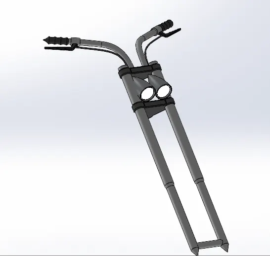
10 Front Fork
11. Chassis:-
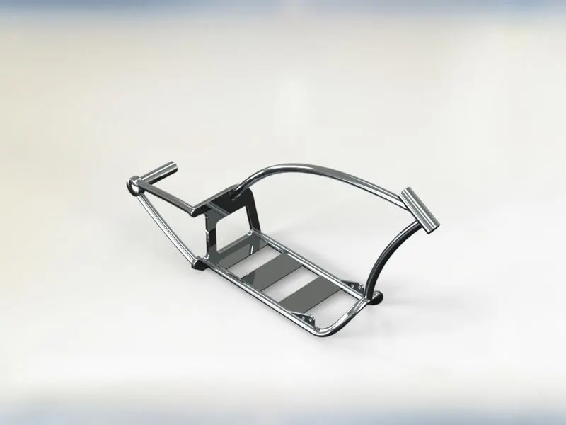
The Chassis is also called a frame. The components like the front fork, gearbox, engine, gas tank, wheels, etc are attached to it. It mostly consists of hollow tubes.
Features used to create chassis-
- Blueprint of American Chopper (Underlay Sketch)
- Sketch
- Offset
- Convert Entity
- Composite Curve
- Projected Curve
- Sweep Boss/Base
- Mirror
- Extrude Boss/Base
- Fillet
- Extrude Cut
- Dome
- Combine
- Chamfer
- Split
- Revolved Boss/Base
- Appearance- Siena
- Save the part- Chassis
Blueprint / Underlay Sketch
Path- Sketch>Tool>Sketch Tools>Sketch Picture
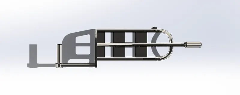
11 Chassis
12. Engine:-
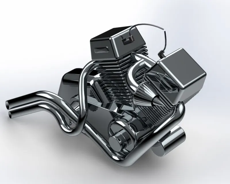
The engine is the main part of the vehicle, where power is generated by the burning of fuel and later transmits the rotational motion to the wheel through chain and sprocket.
Features Used to create an engine
- Blueprint (Underlay Sketch)
- Sketch
- Extrude Boss/Base
- Revolved Boss/Base
- Circular Pattern
- Convert Entity
- Extrude Cut
- Dome
- Fillet
- Chamfer
- Mirror
- Composite Curve
- Projected Curve
- Sweep Boss/Base
- Split
- Appearance- Carbon Steel
- Save the Part- Engine
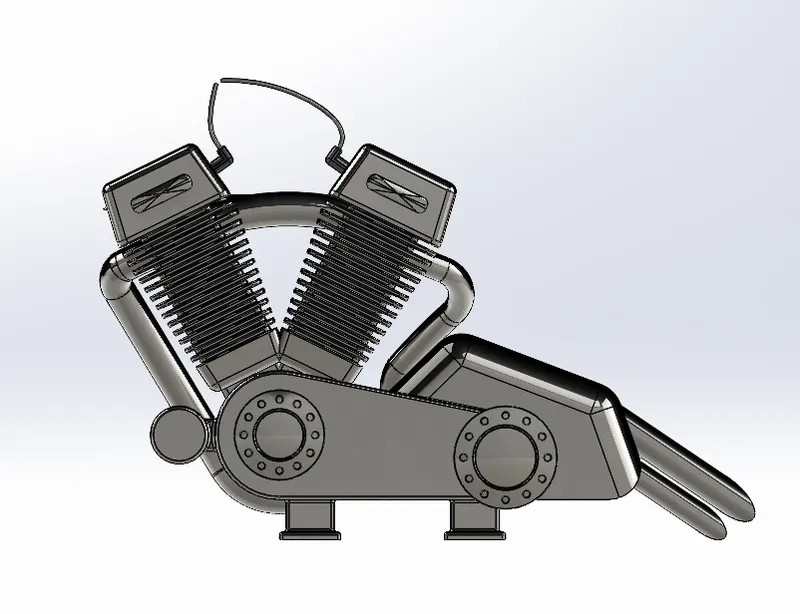 12 Engine
13. Gas Tank:-
The gas tank or fuel tank is used to store the fuel and it is required to run the engine.
The feature used to create a gas tank
- Blueprint sketch
- Sketch
- Projected Curve
- Convert Entity
- Sweep Surface
- Loft Surface
- Boundary Surface
- Surface Trim
- Swept Cut
- Mirror
- Knit Surface
- Split Surface
- Extrude Surface
- Fillet
- Appearance-
Seat- Leather
- Save the part- Gas Tank
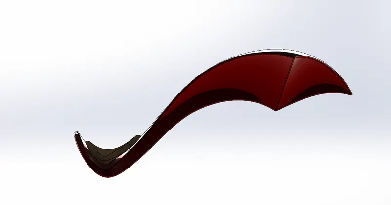
13 Gas Tank
Assembly of American Chopper
- All part modeling windows should be opened.
- Initially, the chassis part is inserted into the main assembly environment by using the insert part option and pressing ok to fix the chassis.
- Similarly, other parts are also inserted into the main assembly environment and give them possible mates to fully define. Following is the part insertion sequence:-
- Chassis
- Engine
- Pedal
- Kickstand
- Transmission Belt
- Oil Tank
- Rear Wheel
- Rear Fender
- Chain
- Gas Tank
- Front Fork
- Front Wheel
- Front Fender
Features used to create assembly-
- Insert Components
- Mates
- Mirror
- Save the assembly- American Chopper
Insert components
We can insert components in the assembly which is needed to be mated with fixed components.
Mates
Mates create geometric relations with the components which are inserted into the assembly. While making assembly we used various types of mates like –
- Standard Mates- concentric, parallel, coincident, tangent, distance, angle, etc.
- Advanced Mates- Limit, Width, etc.
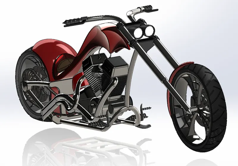
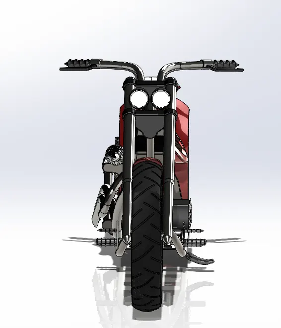
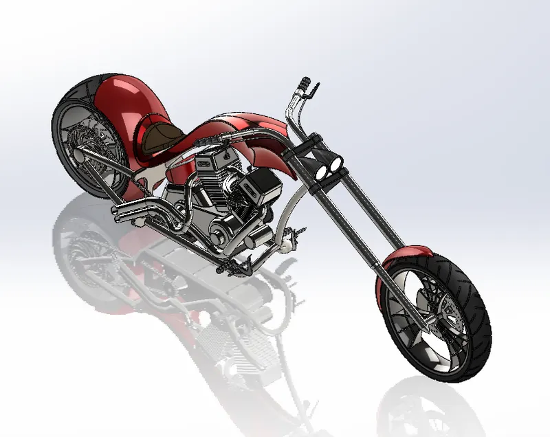
Assembled Chopper:
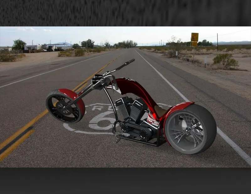
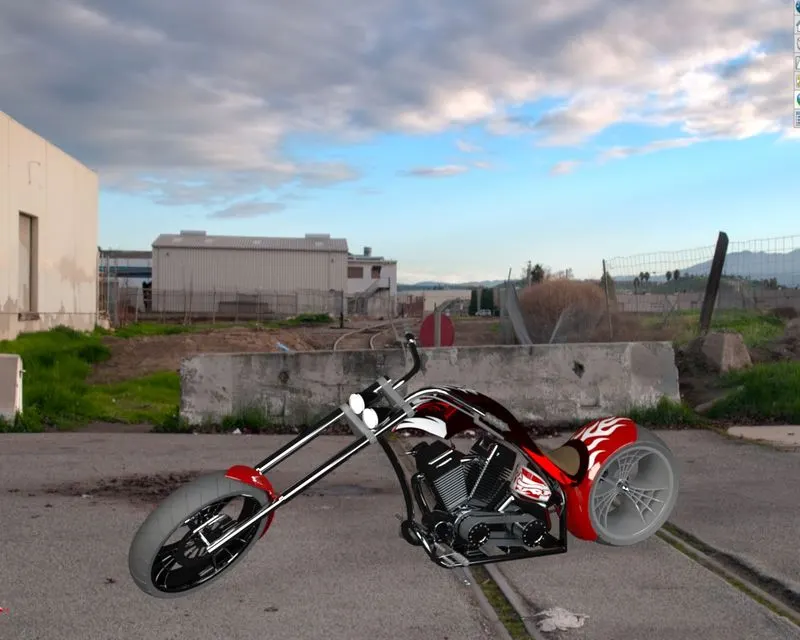
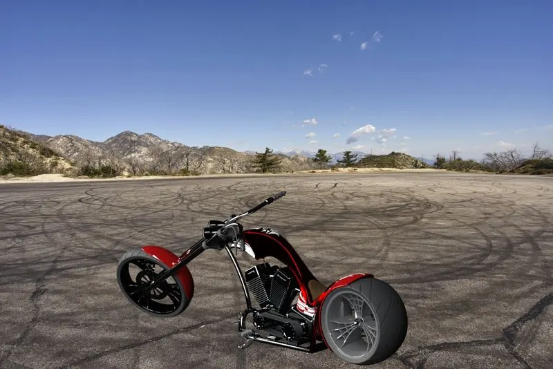
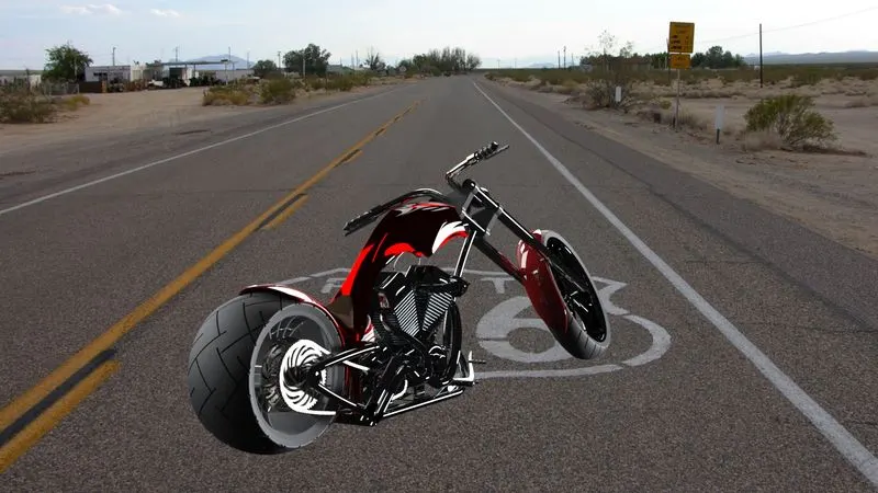
Rendering for American Chopper
Rendering is the process of creating realistic images of the model with the environment.
In rendering various aspects such as camera, light, environment, background scene, appearance, etc. are taken into consideration before final rendering. To check the all-thing preview rendering option is used.
There are two ways of rendering in SOLIDWORKS.
- Photoview 360
- Solidworks Visualize
Parts:
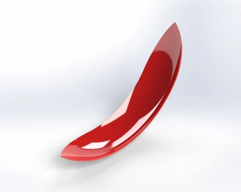
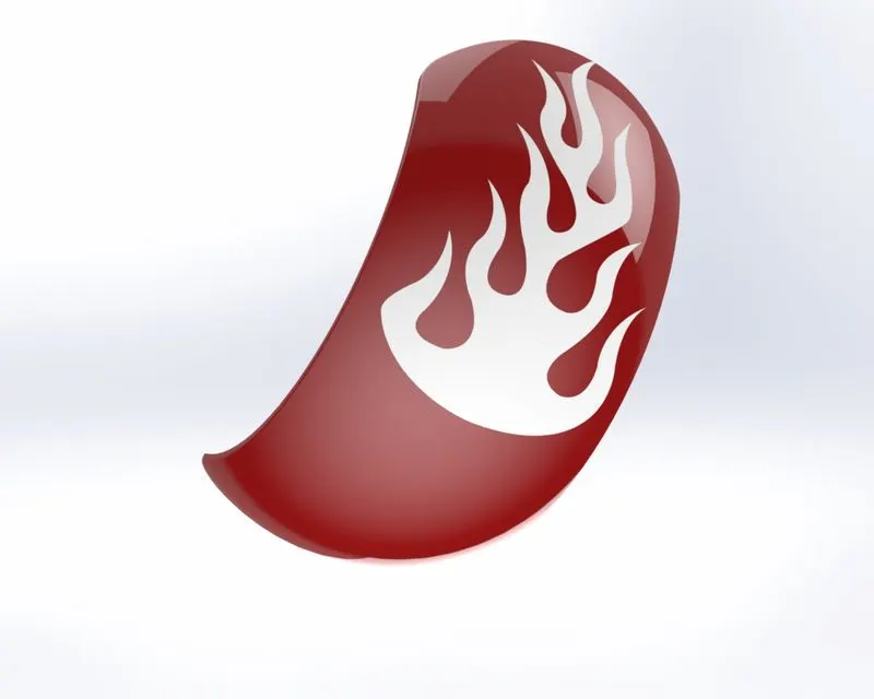
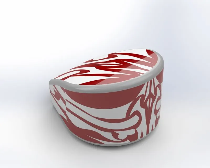
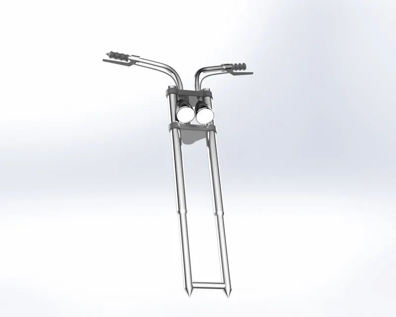
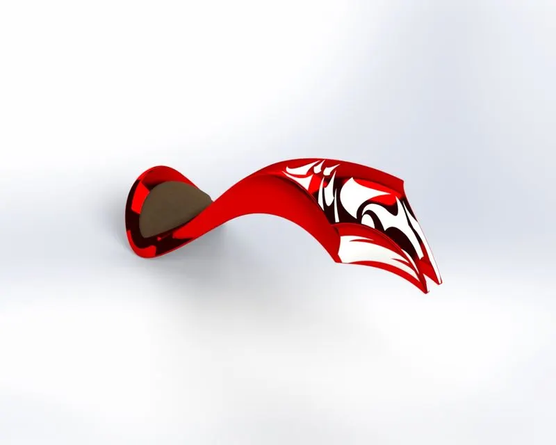
In a photorealistic model, some of the mates and conditions are changed to render a realistic model. So we have to change as per different views before rendering.
Rendered images American Chopper:
Conclusion:-
- The parts are sketched and modeled in the SOLDWORKS.
- The modeled parts are assembled with possible mates into the main assembly of the American chopper.
- The decals are applied to the faces of the parts.
- The realistic images were rendered with the use of both ways “Photoview 360 and Solidworks Visualize.