Photo Realistic Rendering
ASSEMBLY AND PHOTO-REALISTIC RENDERING OF CHOPPER MODEL
- OBJECTIVE :
- Learn to model the components of an American Chopper using Solidworks tools.
- Learn to assembly and position all the components the chopper.
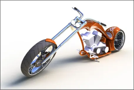
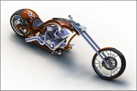
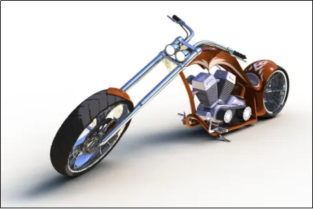
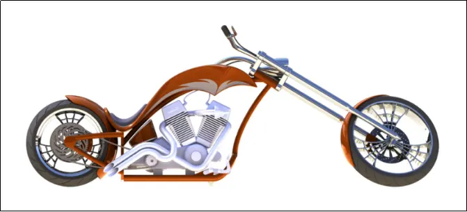
- Learn to do a Photo-realistic rendering of the Chopper using Photo View.
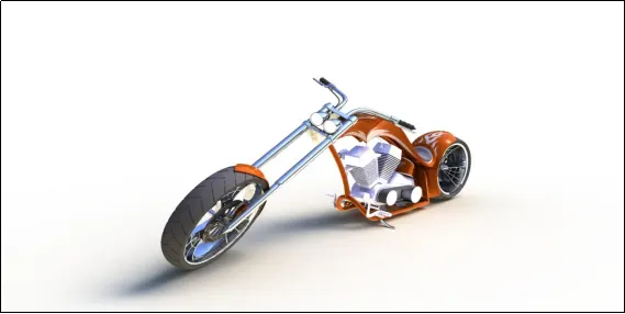
- INTRODUCTION :
I am M Vamsi Krishna and I work as a Mechanical Design Engineer. Here I am going to discuss the modelling process and the tools used to make the American Chopper.
The components modeled for this assembly are:
- Chassis
- Engine
- Pedal
- Kickstand
- Transmission Belt
- Oil Tank
- Rear Wheel
- Rear Fender
- Chain
- Gas Tank
- Front Fork
- Front Wheel
- Front Fender
- DESIGN APPROACH :
A bottom up approach is used in this project. All the parts were made in individual files and assembled in a different file.
- EXPLODED VIEW OF AMERICAN CHOPPER ASSEMBLY :
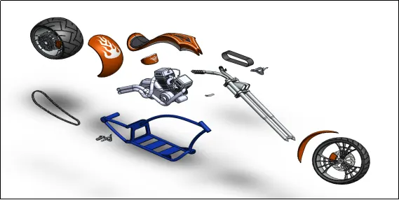
CHAPTER 1 :
- TOOLS USED :
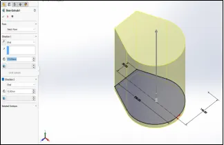
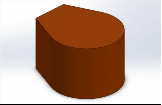
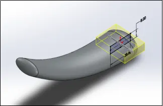
- EXTRUDED BOSS/BASE :
This feature is used to add material using a 2D-sketch in the projected direction. Multiple options such as projection from selected faces and vertex or offset from sketch plane and direction selection are available to control the extrusion are available in the property manager dialog.
Example:-
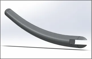
- EXTRUDED CUT :
This feature is used to remove material using a 2D-sketch in the projected direction. Multiple options such as projection from selected faces and vertex or offset from sketch plane and direction selection are available to control the extrusion are available in the property manager dialog.
Example:-
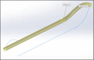
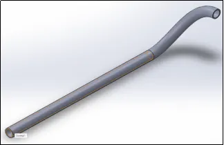
- REVOLVED BOSS/BASE :
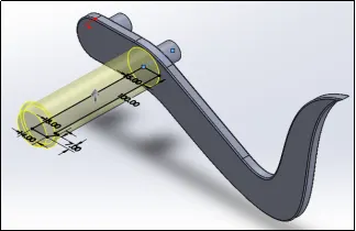
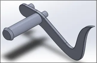
This feature is used to add material by revolving the 2D-sketch about a selected axis.
Example:-
- REVOLVED CUT :
This feature is used to remove material revolved around the selected axis.
Example:-
- HOLE WIZARD :
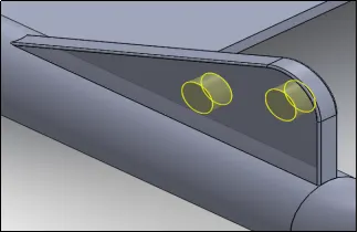
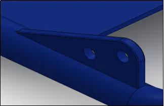
This feature is used to make holes of different types such as counterbore, countersink, screw clearance holes, Slot holes and tapered holes.
Example:-
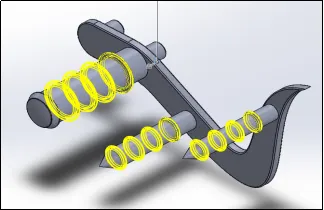
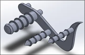
- LINEAR PATTERN :
This feature is used to make pattern of features, faces and bodies along straight edges/lines.
Example:-
- CURVE DRIVE PATTERN :
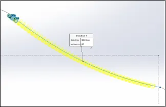
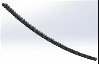
This feature is used to make pattern of features, faces and bodies along a curve.
Example:-
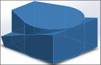
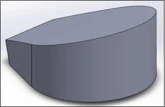
- COMBINE :
This feature is used to combine multiple bodies by adding, subtracting or common multiple bodies.
Example:-
- CHAMFER :
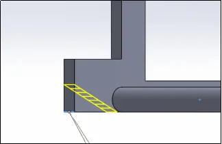
This feature is used to make chamfered edges to avoid sharp edges and corners.
Example:-

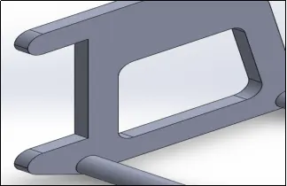
- FILLET:
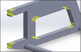
This feature is used to make curved edges to avoid sharp edges and corners.
Example:-
CHAPTER 2 :
- PARTS OF THE AMERICAN CHOPPER ASSEMBLY :
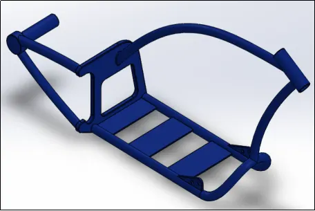
- CHASSIS :
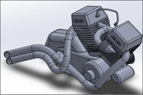
- ENGINE :
- PEDAL :
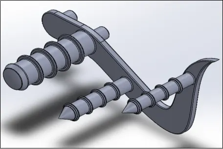
- KICK STAND :
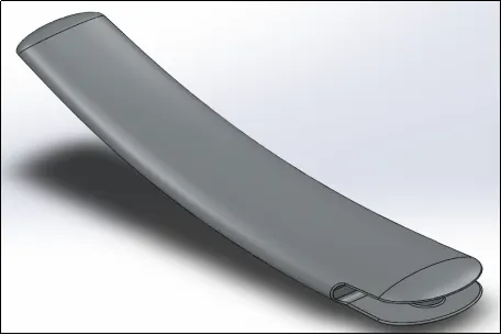
- TRANSMISSION BELT:
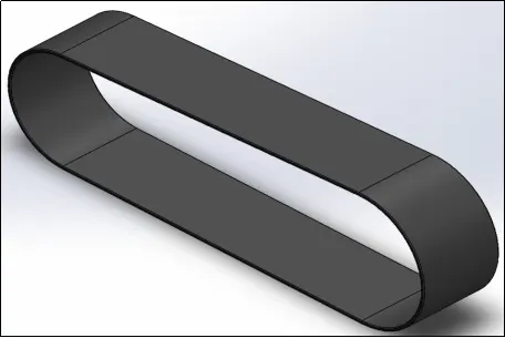
- OIL TANK:
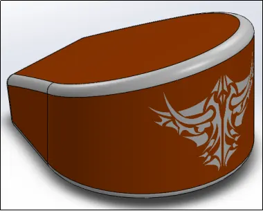
- REAR WHEEL:
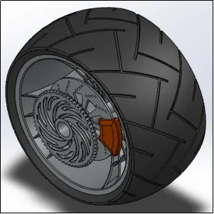
- REAR FENDER:
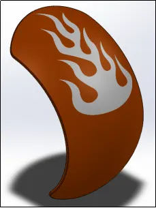
- CHAIN:
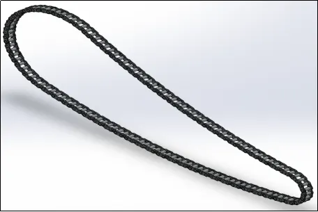
- GAS TANK:
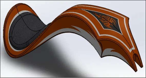
- FRONT FORK:
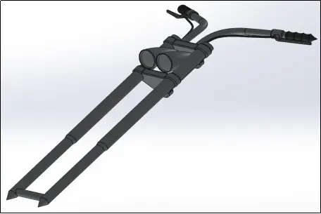
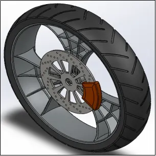
- FRONT WHEEL:
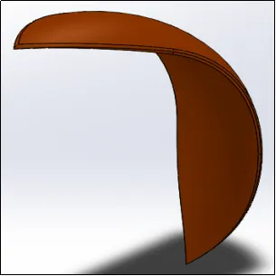
- FRONT FENDER:
CHAPTER 3 : ASSEMBLY OF THE AMERICAN CHOPPER MODEL
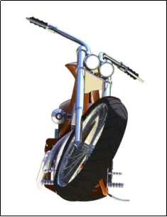
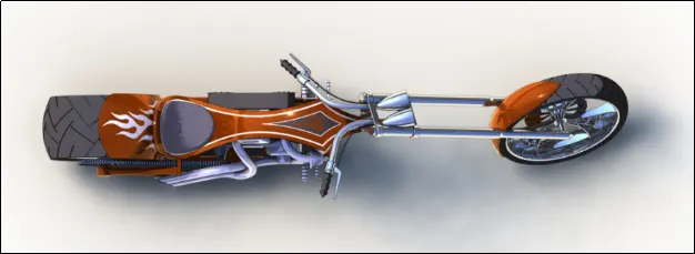
CHAPTER 4 : RENDERING
THANK YOU.