Photo Realistic Rendering
ASSEMBLY AND RENDERING OF AMERICAN CHOPPER
Objective:
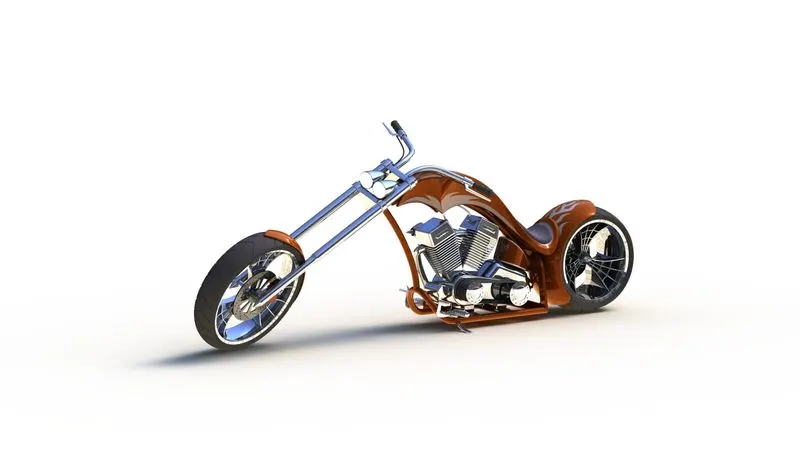
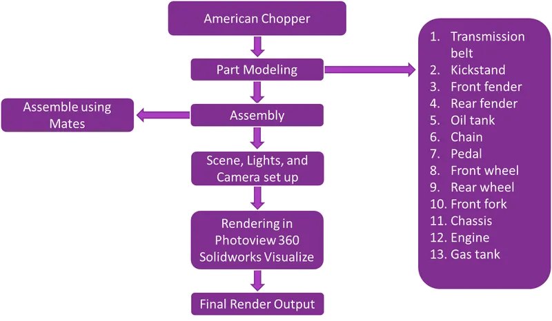
The objective of this project is to create a model of an American chopper with different parts like chassis, engine, fenders, front fork, wheels, etc, assemble with different parts of the chopper, and create a photorealistic model of the chopper and render the model by using software like Solidworks photo view 360 and Solidworks Visualize.
Introduction:
A chopper is a type of custom motorcycle that emerged in the US state of California in the late 1950s. A chopper employs radically modified steering angles and lengthened forks for a stretched-out appearance. They can be built from an original motorcycle which is modified ("chopped") or built from scratch. Some of the characteristic features of choppers are long front ends with extended forks often coupled with an increased rake angle, hardtail frames (frames without rear suspension), very tall "ape hanger" or very short "drag" handlebars, lengthened or stretched frames, and larger than stock front wheels.
Design methodology/approach:
Assembly of Chopper:
The following parts are used for model and assembly in solid works,
- Transmission belt
- Kickstand
- Front fender
- Rear fender
- Oil tank
- Chain
- Pedal
- Front wheel
- Rear wheel
- Front fork
- Chassis
- Engine
- Gas tank
Details of Individual Parts:
1. Transmission Belt:
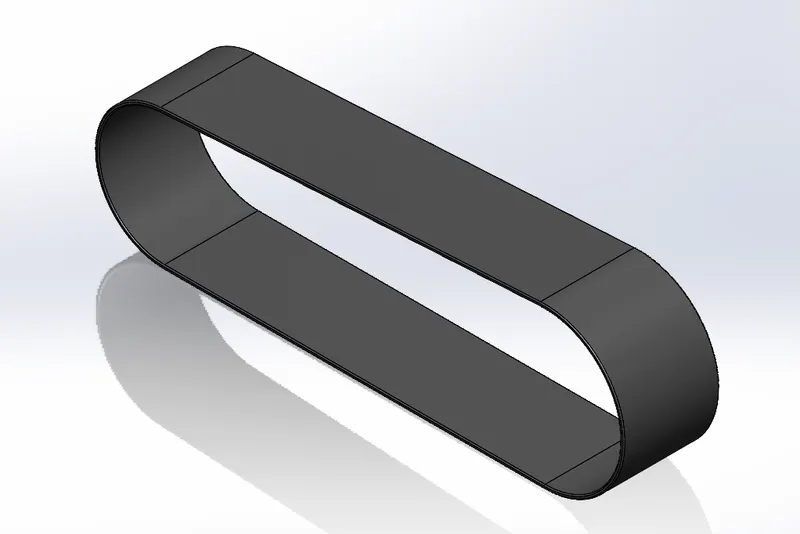
The main purpose of the transmission belt is used to transmit power which is developed inside the engine to the gearbox with maximum efficiency.
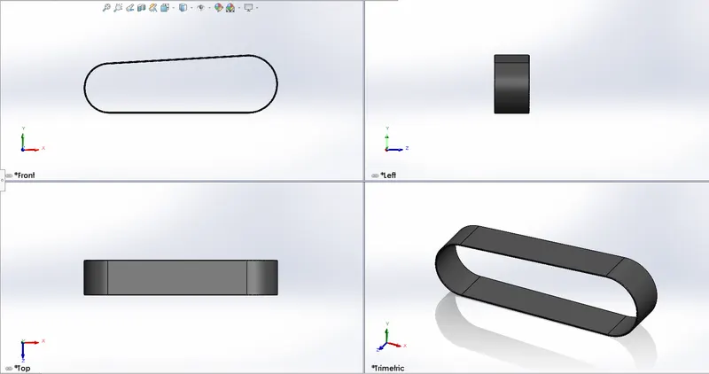
The following transmission belt is designed as per the given dimensions.
Steps In Creating Transmission Belt:
- A sketch of the Transmission belt is constructed using lines & arcs.
- The entire sketch is made offset for 3.5mm without removing the original sketch.
- The length between the centers of the two arcs is 350mm, the Radius of the bigger arc is 70mm Radius of the smaller arc is 60mm.
- A line from the origin of 350mm is made horizontal using horizontal relation and tangency between lines and arcs is maintained using tangency relation.
- The entire sketch is extruded 88mm using Extruded Boss/bass command.
- All edges of the part are filleted for a radius of 1mm.
- The appearance of the part is changed to rubber matte.
2. Kickstand:
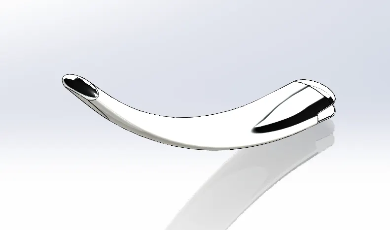
The kickstand is usually more convenient for quickly propping the bike up when parking for a short time since you don't have to lift the bike at all to use it. It can be easier to get a bike off the kickstand than off the center stand on sloping ground in a controlled fashion, especially if the bike is heavy.
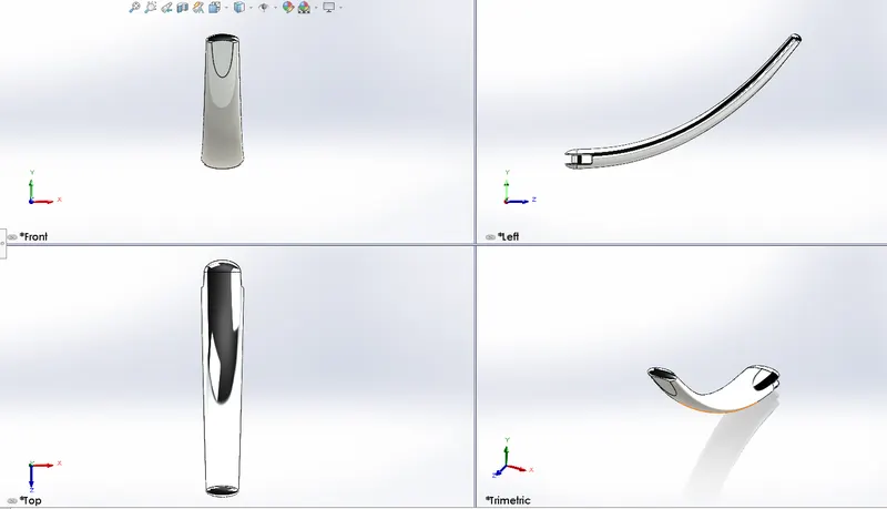
The following KickStand is designed as per the given dimensions.
Steps In Creating Kickstand:
- An ellipse is drawn from the origin in the front plane and a spline is drawn from the origin in the right plane.
- Another ellipse is drawn at the end point of the spline by creating a new plane at the endpoint of the spline using the Reference geometry option.
- Dimensions of the bigger ellipse are 40mm horizontally, and 18mm vertically & are made horizontal to the origin using dynamic relation.
- The spline endpoint is at a distance of 202mm horizontally & 110mm vertically from the origin.
- Dimensions of the smaller ellipse at the newly created plane are 40mm horizontally, and 18mm vertically & are made horizontal to the origin using dynamic relation.
- A loft is created from a bigger ellipse to a smaller ellipse & by selecting the spline using a lofted boss/base.
- An elliptical dome is made at both ends of dimensions 13mm & 5mm respectively.
- A flat face at the bottom of the kickstand is created by removing the material using the "Split" cut bodies option.
- An extruded cut is made at the bigger end by drawing a rectangle of 8*28mm and using "Extruded cut" through all.
- A pivot point is created at the bigger end to fix the frame by creating extruded boss of 9mm diameter.
- Fillets are made to 2mm and 0.5mm sharp edges respectively.
- A chromium plate is used for the entire part.
3. Front Fender:
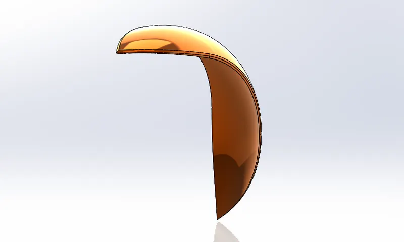
The front fender is mounted above the front wheel, which is used to protect the rider and chopper's other parts from dust, mud, and other particles.
The following Front Fender is designed as per the given dimensions.
Steps In Creating Front Fender:
- A 3-point arc is drawn above the origin in a vertical plane & the same arc is made offset inwards of 6mm.
- Sketch is closed using extend and trim entities.
- A construction line is drawn at the origin in the vertical plane of the required dimension which is used as an axis while revolving the sketch.
- Arc is of width 160mm, a radius of 125mm and the arc center is 280mm above the origin
- Entire sketch is revolved for 5 deg in direction 1 and 130 deg in direction 2 around the axis using revolve extruded boss/bass command
- A required geometry shape is created in the center plane using spline and line commands with a dynamic mirror on, using the sketch the part of the body is removed using the split command at the top end of the body.
- Same procedure is followed at the vertical plane to cut out the part of the body for the desired shape in the bottom end of the body.
- All the edges at top of the body are filleted for a radius of 6mm
- Painted Siena is used for the entire part.
4. Rear Fender:
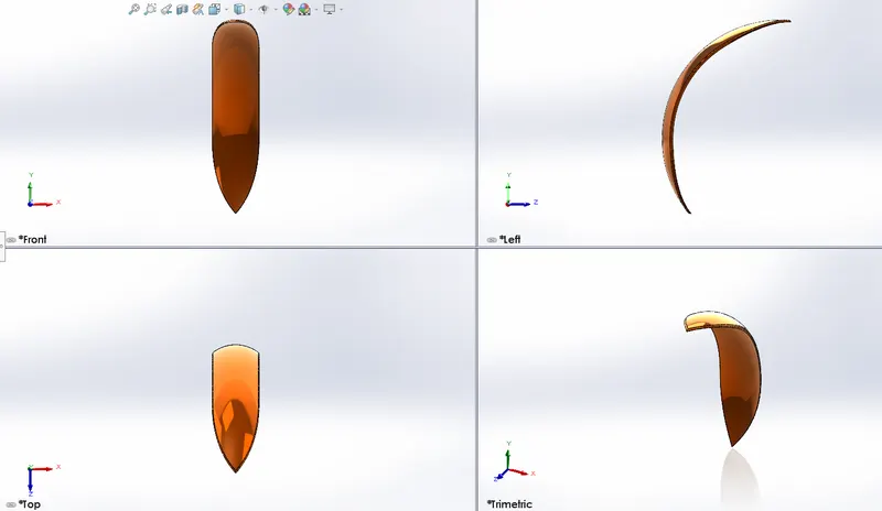
Its primary purpose is to prevent sand, mud, rocks, liquids, and other road sprays from being thrown into the air by the rotating tire. Fenders are typically rigid and can be damaged by contact with the road surface.
The following Rear Fender is designed as per the given dimensions.
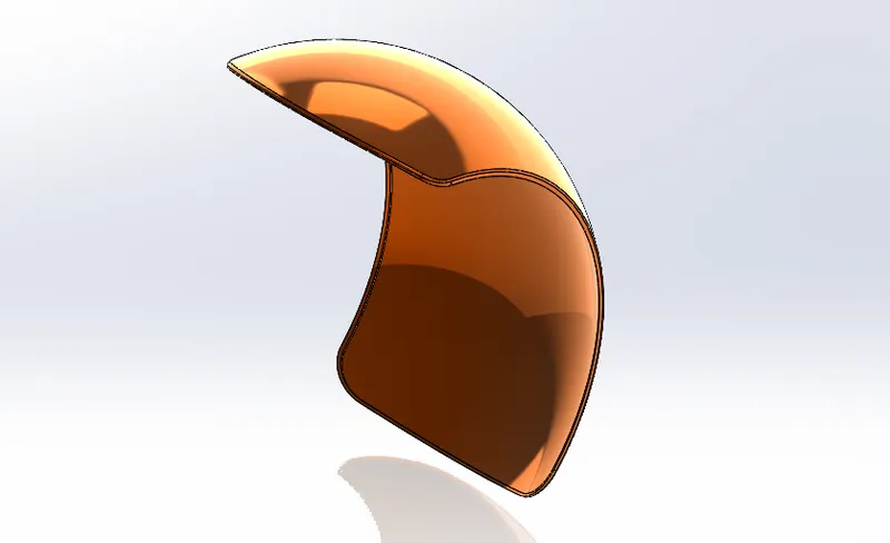
Steps In Creating Rear Fender:
- A 3-point arc is drawn above the origin in a vertical plane & the same arc is made offset inwards of 6mm.
- Sketch is closed using extend and trim entities.
- A construction line is drawn at the origin in the vertical plane of the required dimension which is used as an axis while revolving the sketch.
- Arc is of width 364mm, a radius of 290mm and the arc center is 90mm above the origin
- Entire sketch is revolved for 10 deg in direction 1 and 140 deg in direction 2 around the axis using revolve extruded boss/bass command.
- A sketch of the desired shape is created on the center plane to cut out the part of the body using 3 point arc, using the sketch and construction line created part of the body is removed using the split command.
- All four corner edges of the fender are filleted for a radius of 45mm and the remaining sharp edges are filleted for a radius of 4mm.
- Inside face of the fender is selected and is made hollow of 4mm using the shell command.
- Painted Siena is used for the entire part.
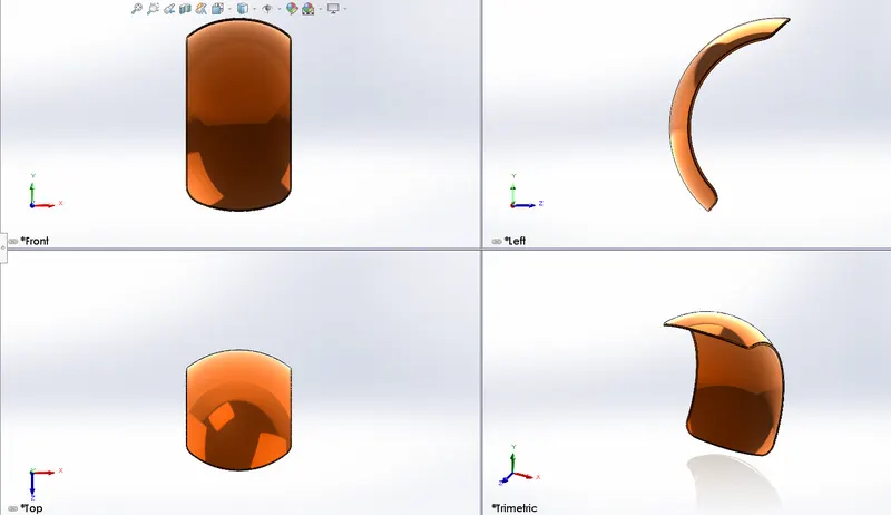
5. Oil Tank:
The oil tank is a hollow section, and the main purpose of the oil tank is used to store the oil and supply the oil to the engine while running the vehicle.
Combine feature and shell are the main features used to create the Oil Tank.
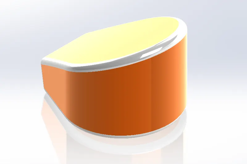
Steps to Create the Oil Tank:
- A 2D Sketch is created as per the given dimension in the top plane.
- The sketch is then extruded 170mm in one direction and 10mm in another.
- A new sketch is created on the midplane( front) and extruded into both directions using all options.
- Combine feature is used to build a common part using both models.
- Fillets are applied at the edges and the shell feature is applied with a thickness of 3mm and previewed using a cut section to ensure that shell is applied.
- Appearance of the oil tank is changed to sienna with white at the edges.
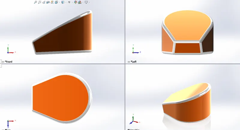
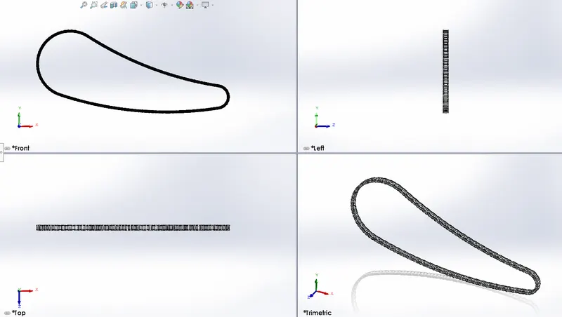
6. Chain:
A chain is a way of transmitting mechanical power from one place to another. It is often used to convey power to the wheels of the vehicle, particularly bicycles and motorcycles. Most often, the power is conveyed by a roller chain, known as the drive chain or transmission chain, passing over a sprocket gear, with the teeth of the gear meshing with the holes in the links of the chain.
Curve-driven patterns, Sketch blocks, and mirrors are the main features used to create the Chain.
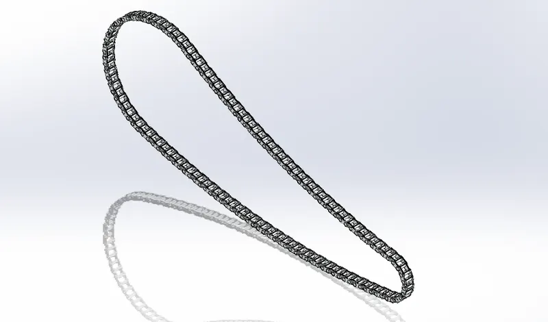
Steps to Create the Chain:
- After renaming the planes sketch is created at the midplane according to the given dimensions.
- A runaway sketch is created at the midplane and blocks are created, namely as chain_link1 and chain_link2, to save them as a separate parts and use them to create the links.
- The blocks are inserted into the 2D sketch created on the midplane and applied certain relations to make it coincident with the curve.
- The blocks are then extruded and fillets are applied at the faces of the pin.
- Curve driven pattern is applied along the curve and some extrudes are drawn manually to perfectly align with the chain path.
- Later the solid bodies are classified into chain plates and pins in separate folders to keep them more organized and the chain plates are mirrored using a mirror entity.
- Chrome Appearance is applied to the chain.
7. Pedal:
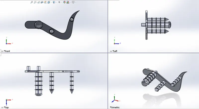
The main purpose of the pedal is that place the leg on top of the for a resting position and is sometimes used for changing the gears by keeping the leg on the pedal.
Linear pattern, revolve, chamfer and dome are the main features used to create the Pedal.
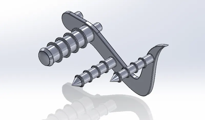
Steps to Create the Pedal:
- 2D sketch is created at the front plane as per the given dimensions and extruded using an extruded boss/base up to 8mm.
- A new sketch is created on the front face of the model and extruded up to 20mm.
- Another sketch is created on the other face of the model and is revolved using revolved boss/base feature.
- Dome feature is applied at the end face of the revolved part.
- Unsymmetrical chamfer is applied to the other two parts.
- A new sketch is created by using the offset entities option at the base of the three parts and is extruded from the face at an offset of 20mm of 2.5mm.
- Fillets are applied to the newly created extruded parts and a linear pattern is applied to create four instances of the same at a spacing of 20mm.
- Fillets are applied to the remaining edges of the model.
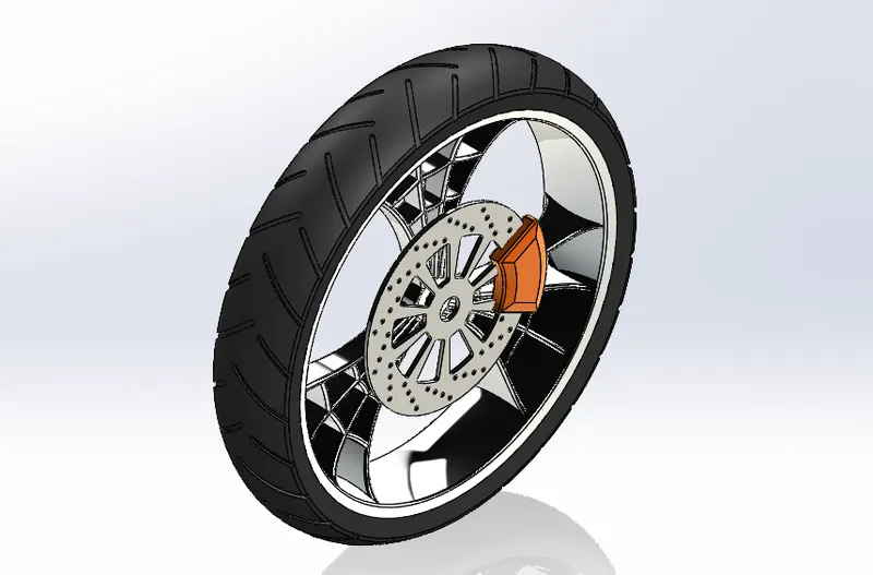
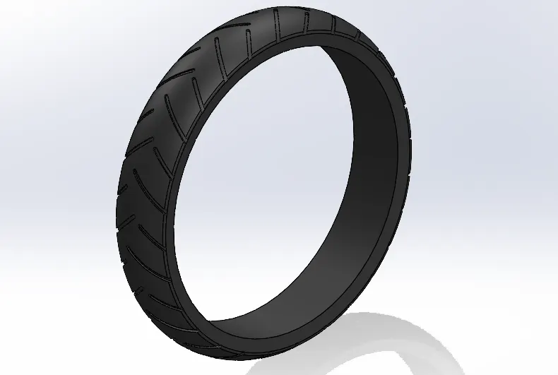
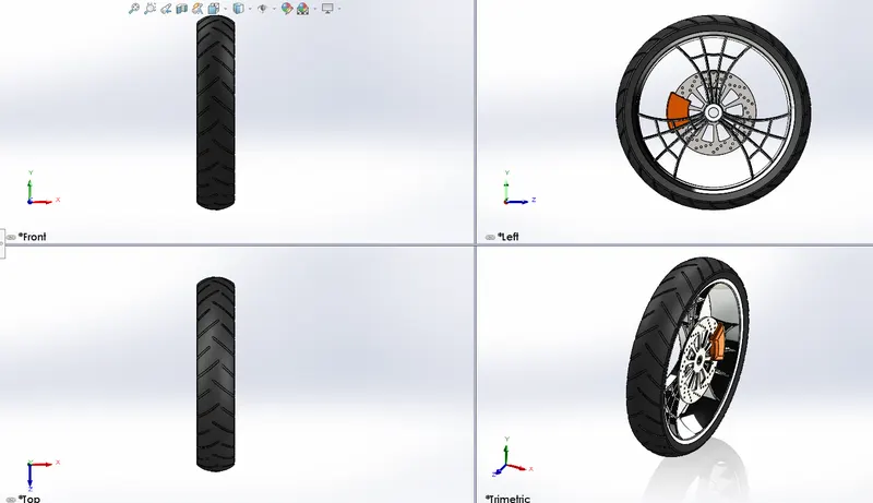
8. Front Wheel:
Motorcycle wheels are made to cope with radial and axial forces. They also provide a way of mounting other critical components such as the brakes, final drive, and suspension. Wheels, and anything directly connected to them, are considered to be unsprung mass. Traditionally motorcycles used wire-spoked wheels with inner tubes and pneumatic tires.
It consists of 4 parts,
- Rim
- Rotor
- Caliper
- Tire
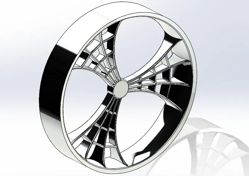
Rim:
- The outer rim profile was created as per the given dimensions and modeled by using revolve command.
- The spider web design was modeled by using the commands extrude, extrude cut, circular pattern, and revolve cut.
- Then the appearance changed to chromium metal material.
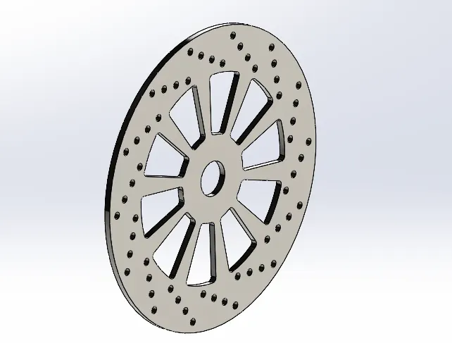
Rotor:
- The Rotor profile was created as per the given dimensions and modeled by using extrude command.
- The rotor design was modeled by using the commands extrude, extrude cut, linear pattern, and circular pattern.
- Then the appearance changed to Carbon Steel material.
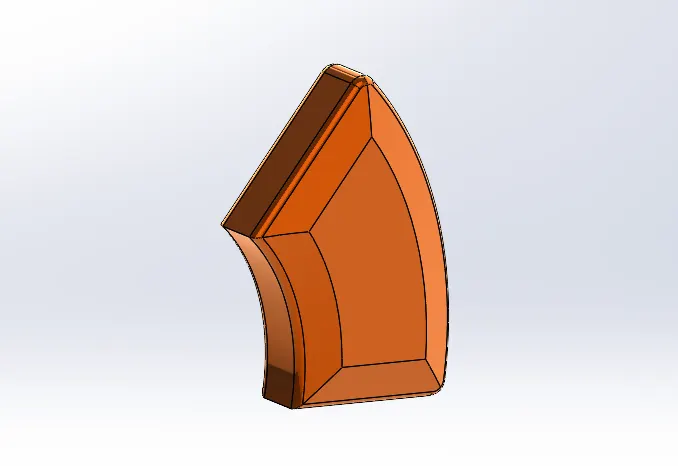
Caliper:
- The Caliper profile was created as per the given dimensions and modeled by using extrude command.
- The Caliper design was modeled by using the commands extrude, champer, and fillets.
- Then the appearance changed to Sienna material.
Tire:
- The Rotor profile was created as per the given dimensions and modeled by using revolve command.
- The rotor design was modeled by using the commands extrude, extrude cut, linear pattern, and circular pattern.
- Then the appearance changed to matte rubber material.
Different Views:
9. Rear Wheel:
The chain is connected between the engine and rear wheel to drive the vehicle and the power is developed inside the engine. The rear wheel has a disc and sprocket attachment.
It consists of 5 parts,
- Rim
- Rotor
- Caliper
- Sprocket
- Tire
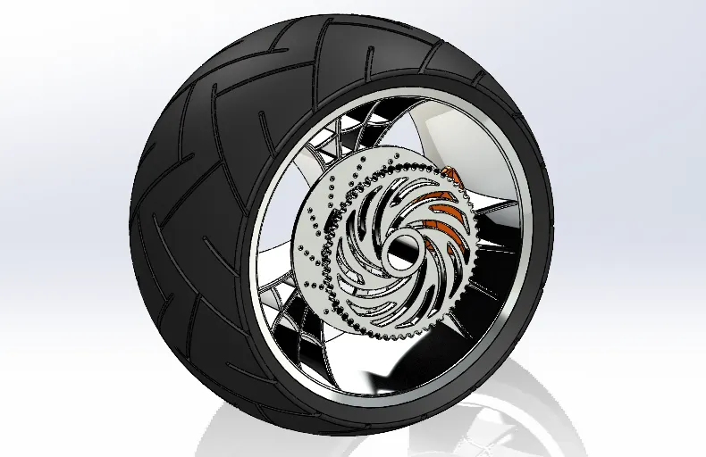
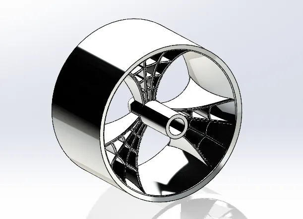
Rim:
- The outer rim profile was created as per the given dimensions and modeled by using revolve command.
- The spider web design was modeled by using the commands extrude, extrude cut, circular pattern, and revolve cut.
- Then the appearance changed to chromium metal material.
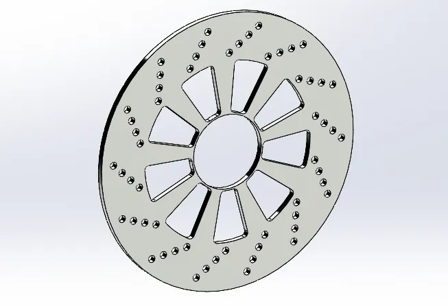
Rotor:
- The Rotor profile was created as per the given dimensions and modeled by using extrude command.
- The rotor design was modeled by using the commands extrude, extrude cut, linear pattern, and circular pattern.
- Then the appearance changed to chromium metal material.
Caliper:
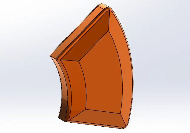
- The Caliper profile was created as per the given dimensions and modeled by using extrude command.
- The Caliper design was modeled by using the commands extrude, champer, and fillets.
- Then the appearance changed to Sienna material.
Sprocket:
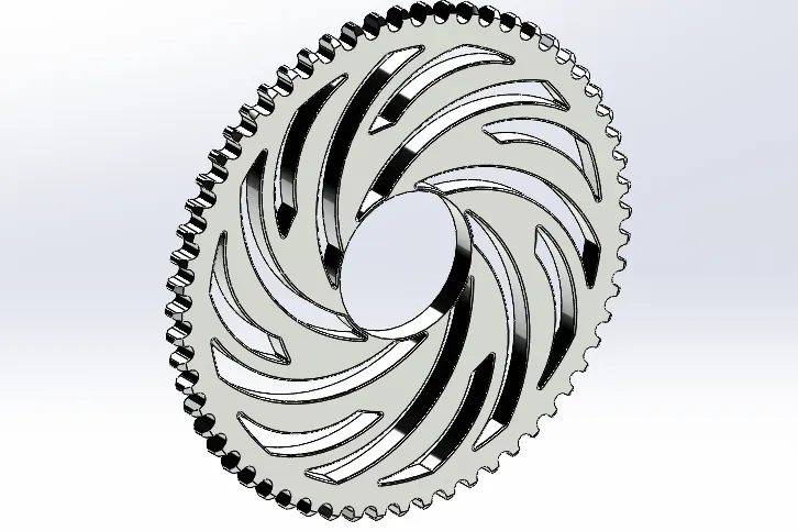
- The sprocket profile was created as per the given dimensions and modeled by using extrude command.
- The sprocket design was modeled by using the commands extrude, extrude cut, and circular pattern.
- Then the appearance changed to chromium metal material.
Tire:
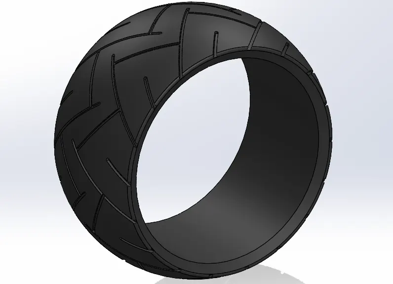
- The Rotor profile was created as per the given dimensions and modeled by using revolve command.
- The rotor design was modeled by using the commands extrude, extrude cut, linear pattern, and circular pattern.
- Then the appearance changed to matte rubber material.
Different Views:
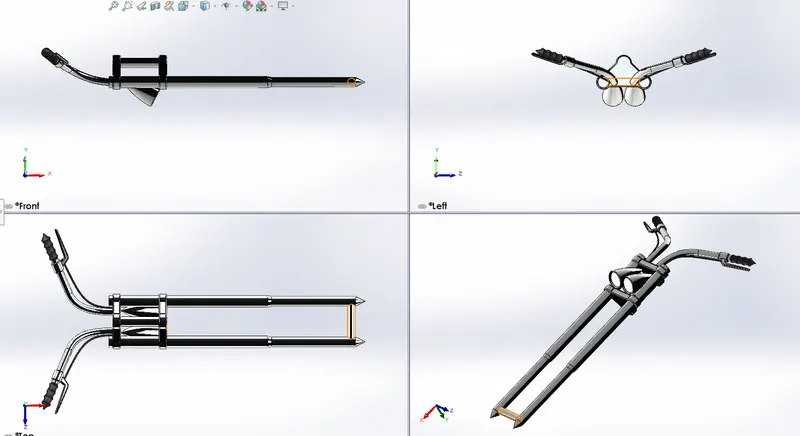
10. Front Fork:
The front fork prevents excessive weight on the front wheel during drastic sudden applications break and softens bumping when driving on rough road surfaces. The front fork maintains proper damping through traction with the road surface.
The Front Fork profile was created as per the given dimensions.
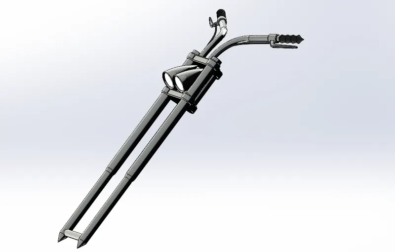
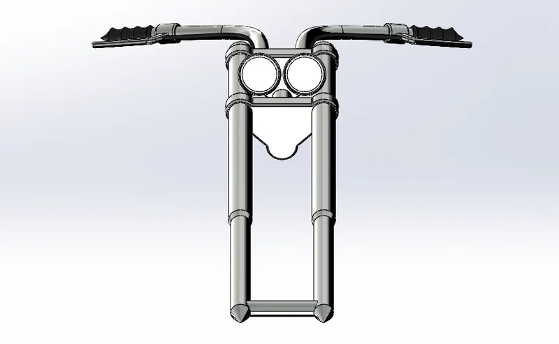
The Front Fork design was modeled by using different commands such as,
- Fillet
- Trim
- Spline
- 3-point arc
- Smart Dimensions
- Appearance
- Dome
- Mirror Entities
- Body-Move/Copy
- Combine
- Cut Extrude
- Cut revolve
- Circular pattern
- Linear pattern
- Projected curve
- Reference Plane
- Extruded boss/base, swept boss/base, and revolved boss/base.
Appearance: Chromium Metal, Glossy Rubber, and Area light for Headlamp
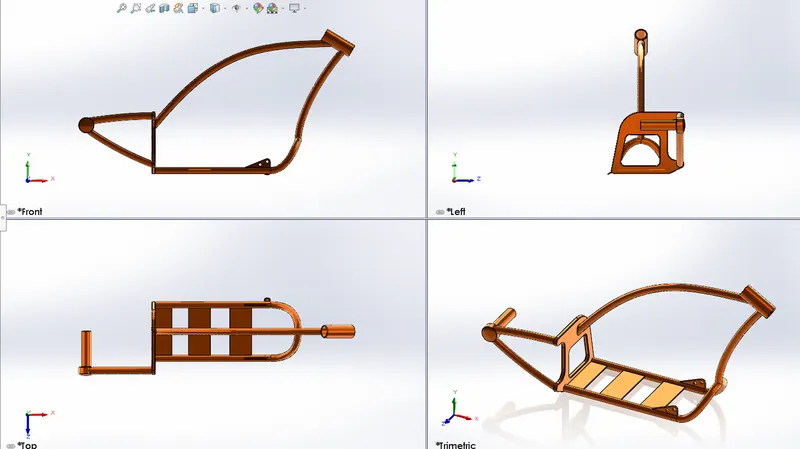
11. Chassis:
A motorcycle’s chassis or frame forms its skeleton. All the components of a motorcycle, like the suspension, wheels, fuel tank, seats, handlebars, etc, are attached to this base structure which lends a motorcycle its strength and ability to handle well. Motorcycle frames come in a variety of materials and shapes, based on the budgetary and performance-related limits of the end product.
The Chassis profile was created as per the given dimensions.
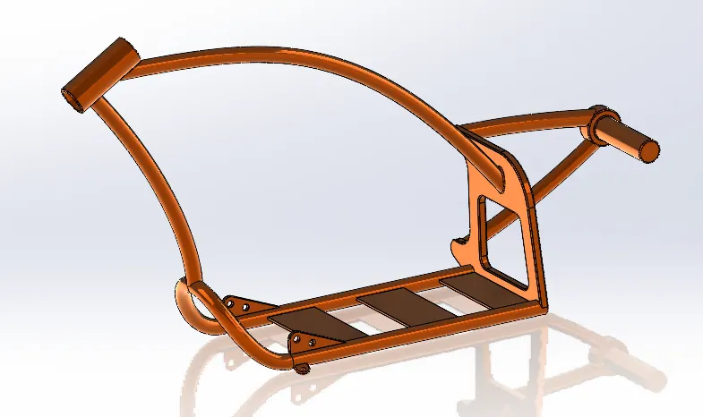
The Chassis design was modeled by using different commands such as,
- Fillet
- Trim
- Spline
- 3-point arc
- Smart Dimensions
- Appearance
- Dome
- Mirror Entities
- Body-Move/Copy
- Combine
- Cut Extrude
- Pierce
- Projected curve
- Reference Plane
- Extruded boss/base, swept boss/base.
Appearance: Siena
12. Engine:
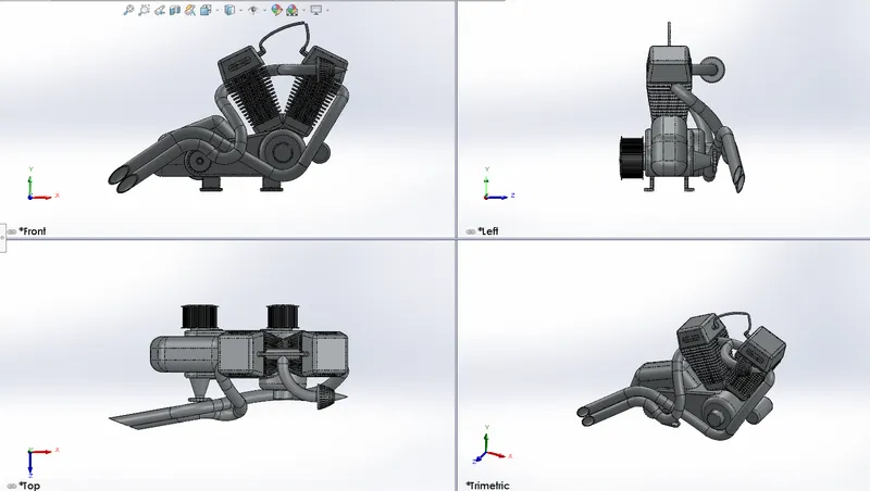
The engine is the prime mover of any vehicle; it converts chemical energy into heat energy by burning the air-fuel mixture inside the engine cylinder. Motorcycle engines are typically two-stroke or four-stroke internal combustion engines, but other engine types, such as Wrankels and electric motors, have been used. Then heat energy is converted into mechanical energy by rotating the parts like the flywheel, clutch, gearbox, etc…. then power is transmitted to the rear wheels.
The Engine profile was created as per the given dimensions.
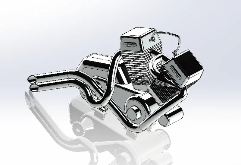
The Engine design was modeled by using different commands such as,
- Fillet
- Trim
- Spline
- 3-point arc
- Smart Dimensions
- Appearance
- Dome
- Mirror Entities
- Body-Move/Copy
- Combine
- Cut Extrude
- Pierce
- Composite curves
- Projected curve
- Reference Plane
- Extruded boss/base, swept boss/base.
Appearance: Chromium plate
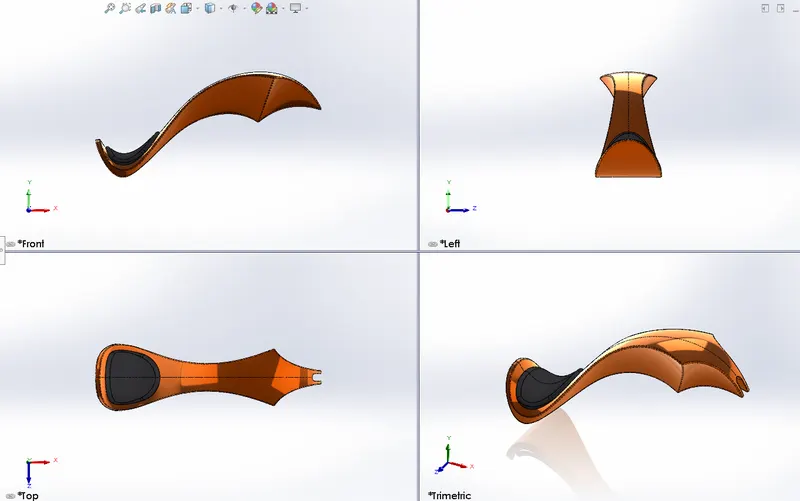
13. Gas Tank:
The main purpose of the gas tank is used to store the gas. It supplies the gas when the engine required it.
I used surface features instead of solid ones in this gas tank model.
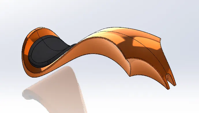
The gas tank profile was created as per the given dimensions.
The gas tank design was modeled by using different commands such as,
- Surface Sweep
- Surface Trim
- Surace Knit
- Boundary Surface
- Surface Loft
- Cut Sweep
- Shell
- Spline
- 3-point arc
- Smart Dimensions
- Appearance
- Fillet
- Mirror
- Combine
- Pierce
- Projected curve
- Reference Plane
Appearance: Siena, Grey Cotton for the seat.
Final Assembly:
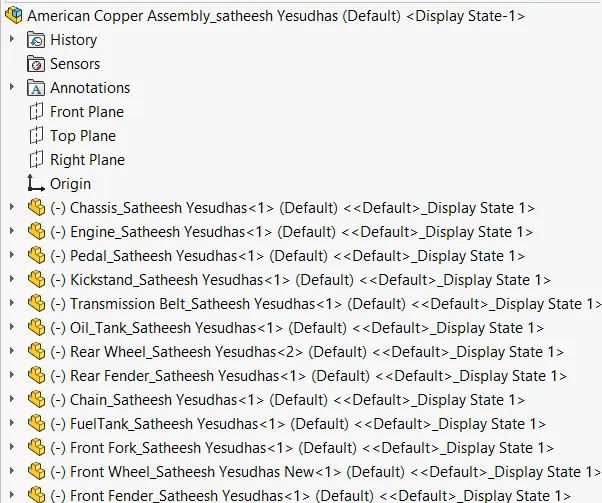
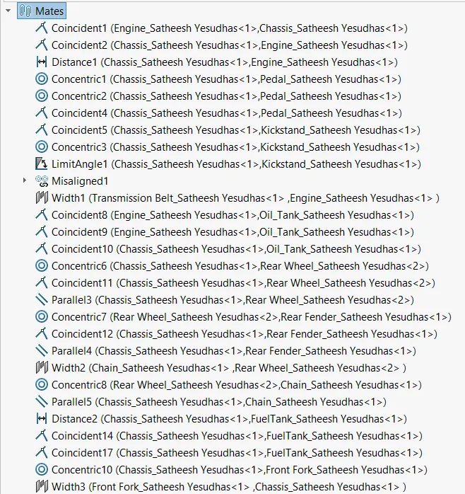
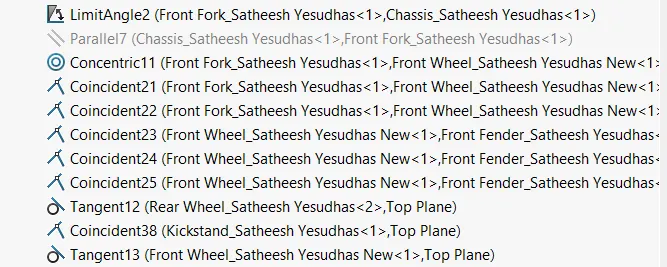
The above parts are designed individually and then assembled. The main purpose of the assembly of the chopper is that assembly all individual parts with suitable mates.
Tree Structure of the assembly:
Mates used to Assemble the parts:
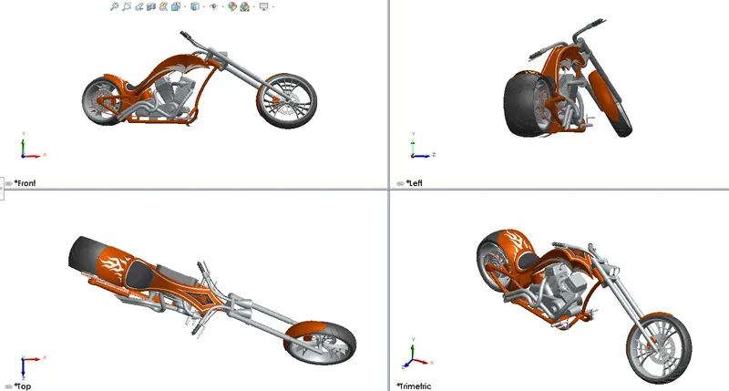
Rendering of the Chopper:
Render:
In 3-D graphic design, rendering is the process of adding shading, color, and lamination to a 2-D or 3-D wireframe to create life-like images on a screen. Rendering may be done ahead of time (pre-rendering) or it can be done in on-the-fly in real-time.
In this project., Solidworks photo view 360 and Solidworks Visualize are used to render the final assembly part in different scenes.
Appearance:
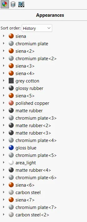
Appearance Design means the appearance presented by an object, formed in hardware or by software that creates a visual impression on an observer. Appearance Design refers to the ornamental and not the functional aspects of an object.
In this project, the Chromium plate, matte rubber, Siena, Grey Cotton, carbon steel, Glossy Rubber, and Area light for Headlamps are used.
Decals:
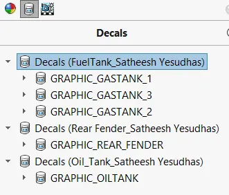
Decal, also called Decalcomania, design that is printed on specially prepared paper to form a film that can be transferred to any surface. Such films are widely used for decorating and labeling any objects that cannot be run through a press. Decals are made in a variety of ways, depending upon the need to be served.
In this project, 3 decals were used on the gas tank, rear fender, and oil tank.
Scene, Light, and Camera:
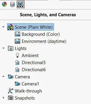
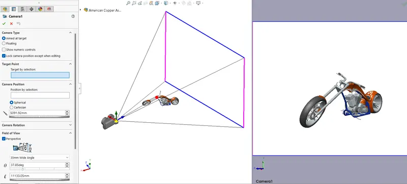
- The scene, lights, and Cameras play a major role in the rendering process, they decide the scene view and lighting.
- To set the scene first the background is set as plain white then the environment is set as daytime it also gives an adequate amount of light to the scene.
- Then the camera is set to give the most appropriate view of the Chopper.
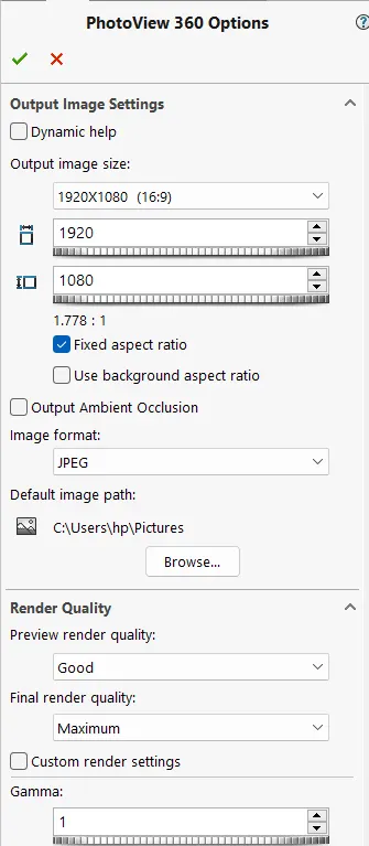
Rendering in Photoview 360:
It is an add-in from the Solidworks software. By enabling photo view 360 we can render the final scene concerning the scene, lights, and camera view.
We can play with the options to get accurate render images.
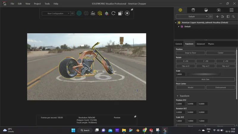
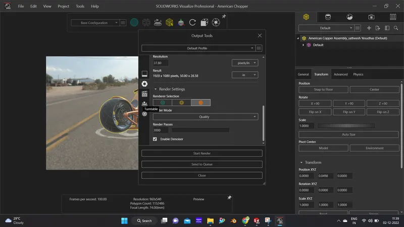
Rendering in Solid works Visualize:
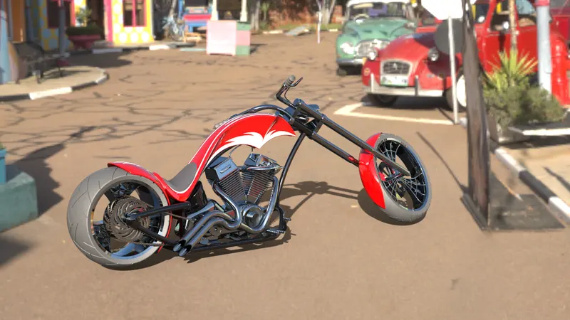
It is used to render the model with different hdri backgrounds we can also adjust the camera and lights to get an accurate view and lighting.
Final Rendered Images:
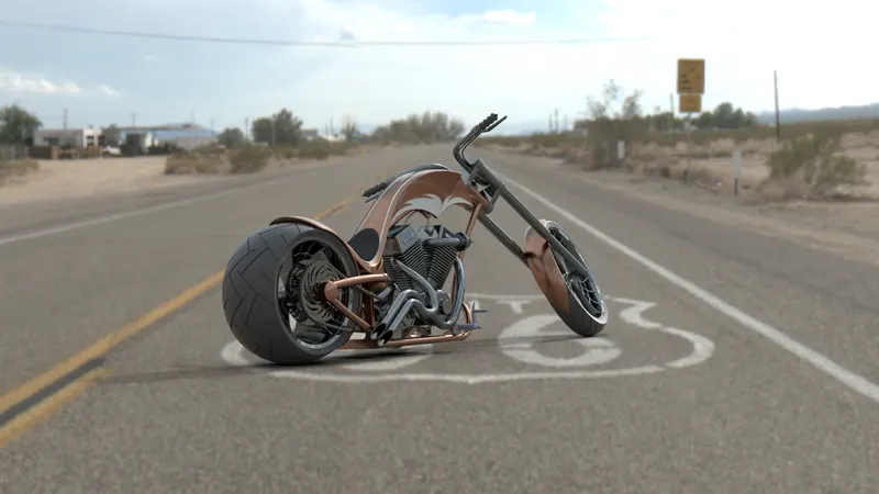
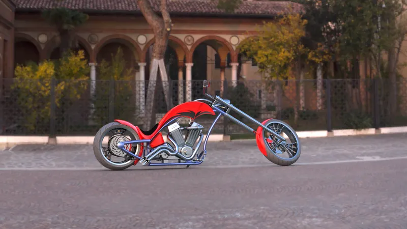
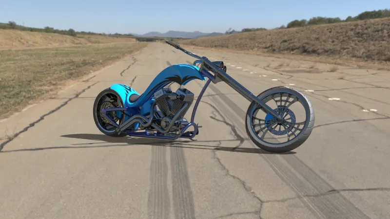
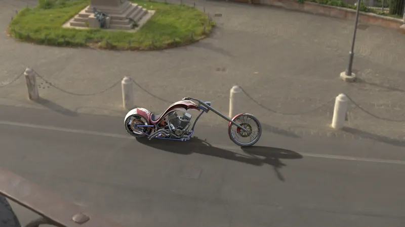
Conclusion:
Thus the modeling, assembling, and rendering of an American Chopper were completed by using different commands in Solidworks and Solidworks Visualize.