Photo Realistic Rendering
REPORT
American Chopper Modeling and Rendering in SOLIDWORKS
To begin with, It should be understood by any engineer that the complete development of any Product is done through various steps, starting from concept building, prototype building and till market launch furthermore, improvisation using customer feedback.
But most of the steps must require a virtual environment that helps to visualize understand and improve with high accuracy in less time and in a cost-effective way, here comes the role of software.
These help in faster and cheaper R&D of Vehicles.
Coming to the topic I am dealing now with, We definitely need a 3D modeling software/ tool for the building of an American chopper the leading industrial 3D modeling tool that is most accurate along with a user-friendly interface is SOLIDWORKS. SOLIDWORKS is a solid modeling computer-aided design (CAD) and computer-aided engineering (CAE) program published by Dassault Systems.
Then basically what actually an American Chopper is..?
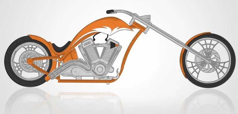
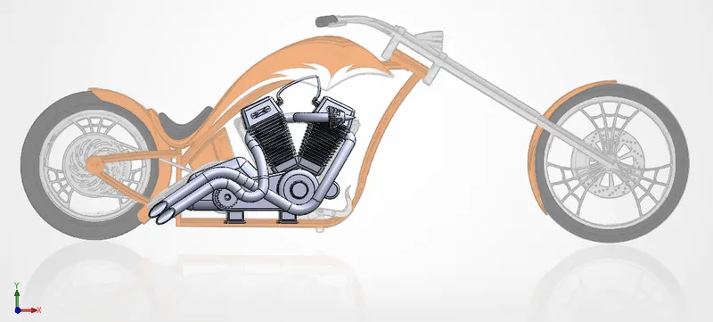
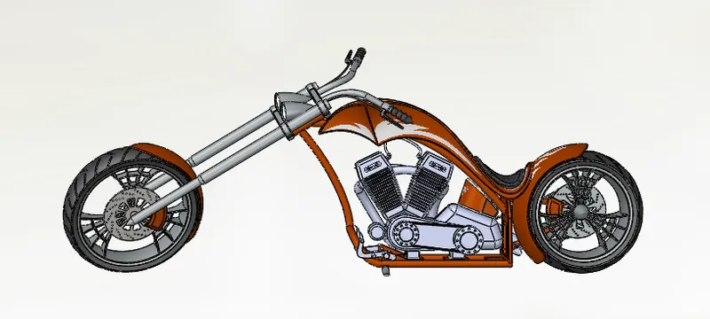
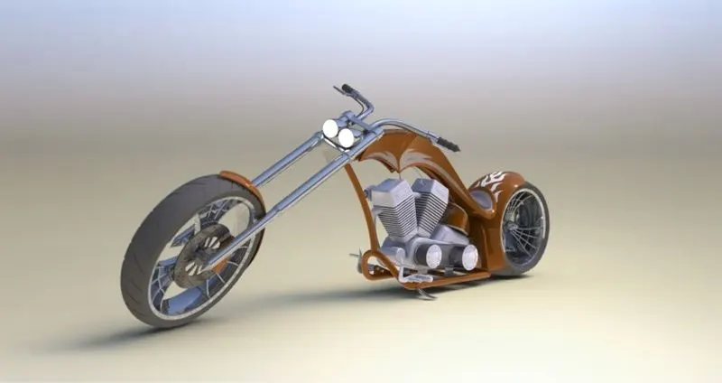
As the picture defines itself, American Chopper are bikes with, high rake angles and trail, low seat heights, low ground clearance, long wheelbase, long front suspension travel. Most generally have webbed Rim, having wider and less diameter Rear tire but larger front tire, Very Curvy exhaust manifold, and Retro Headlamp, The rider sits with the upper torso upright or leaning slightly rearward. The foot pegs are in such a position such that the rider has to extend their legs forward. Handlebars tend to be high and wide. The emphasis is on comfort while compromising cornering ability because of low ground clearance and the greater likelihood of scraping foot pegs, floor boards, or other parts if turns are taken at the speeds other motorcycles can more readily accomplish.

DESIGN METHODOLOGY:
Lets get into the software/ tool
SOLIDWORKS has three basic workbenches namely: Part, Assembly and Drawing/ Drafting.
I begin with modeling of individual part designs, which can be finally assembled together to get a perfect output, it should be noted that the same step is followed in real industrial assembly also where they bring separate parts from various vendors or various departments of manufacturing and finally they get assembled in an assembly line.
For that I used a jpeg image as a reference.
TOTAL 13 PARTS EXCLUDING MIRROR PART OF PEDAL
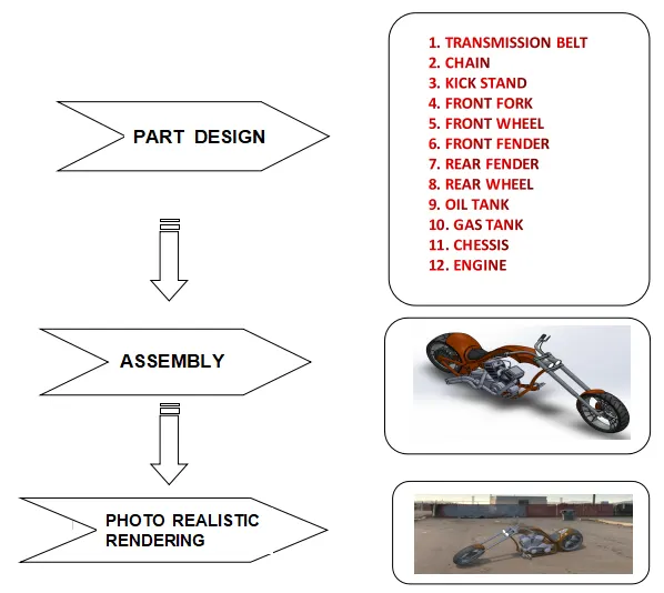
PARTS DESIGN
- TRANSMISSION BELT
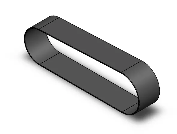
A transmission belt is a component used to transmit power from one shaft/ pulley or a rotating component to another. These belts are made mostly of Highly durable Rubber material. The transmission belt used in the chopper is used to drive the chain shaft driven by the engine flywheel.
- CHAIN
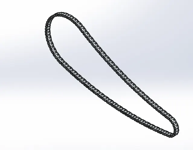
A chain is also a Power transmitting component but of positive drive type, I.e zero slip. here set of several links made of small plates and pin joints, connected in a loop to make a chain component. This is mainly used to transmit power from one shaft to another using sprockets as connecting means to the shafts.
- KICKSTAND
A kickstand or Side stand is used to support the motorcycle in rest position mainly in leaning position. The kickstand is mounted to the chassis through a mounting point. This component should have high tensile/compressive strength to withstand the load of bike while in rest position. The side stand is mounted generally on the left side of the chassis lower side and has a free movement of 80-90 degrees so that stand can be swayed up when not required or while driving.
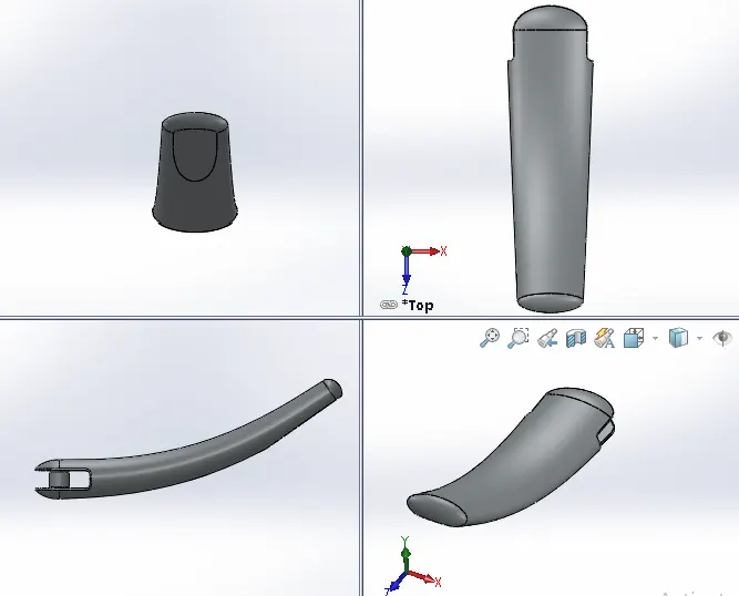
- FRONT FORK
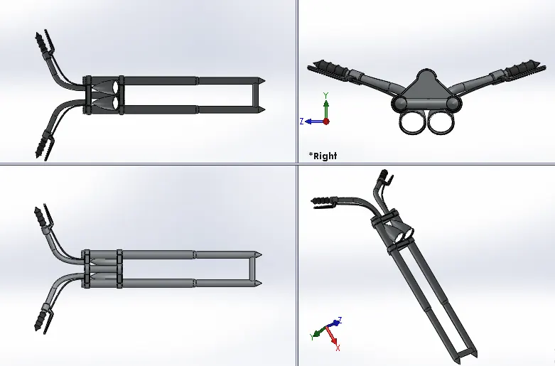
Front Fork is the component that helps in directional control and maneuverability of the motorcycle. Its efficient design helps in better ride and handling of the motorcycle. It also houses various sub-components such as headlights, handle-bars, handle-grip, Triple clamps, Brake lever, clutch lever, cables and axle. It consists of front suspension component which is generally called telescopic forks. It is a 2-piece unit with hollow tube consisting of suspension oil and another piece a solid one which compresses the oil while tackling a bump or rough road surface.
- FRONT WHEEL
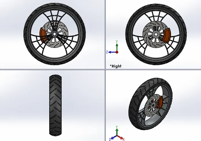
Wheel consists of the rims, tube and the tire which make it the component that makes connection between the motorcycle and the ground. The rim is an important strength component which ensures safe load carrying capacity of the bike. It should have high compressive strength so as to ensure safety while moving. It should be able to absorb shocks and impacts. The tires are the main contact surface to the ground. It is generally made up of rubber to ensure flexibility and bump absorption. The tires contain treads which provides grip to the road. The wheel also houses a Disc brake rotor and its calliper. Front wheels of choppers are always larger than the rear wheel with narrow section as compared to the rear one.
- FRONT FENDER
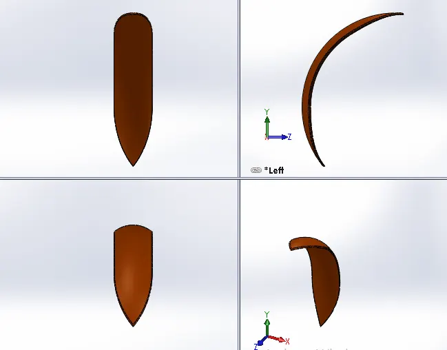
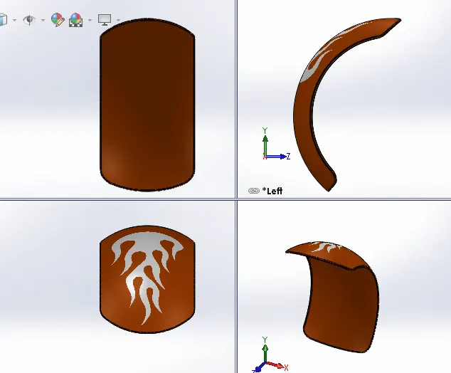
A fender is an automobile part that is bound to the vehicle frame and is placed as a cover on the upper side of the tires. Its primary purpose is to prevent sand, mud, rocks, liquids, and other road spray from being thrown into the air by the rotating tire. Front wheels require the fenders to provide mud and gravel protection on the rear side i.e., the rider side and the engine. This part is also known as mud guard.
- REAR FENDER
This follows the same need as of Front fender but for Rear wheel.
- REAR WHEEL
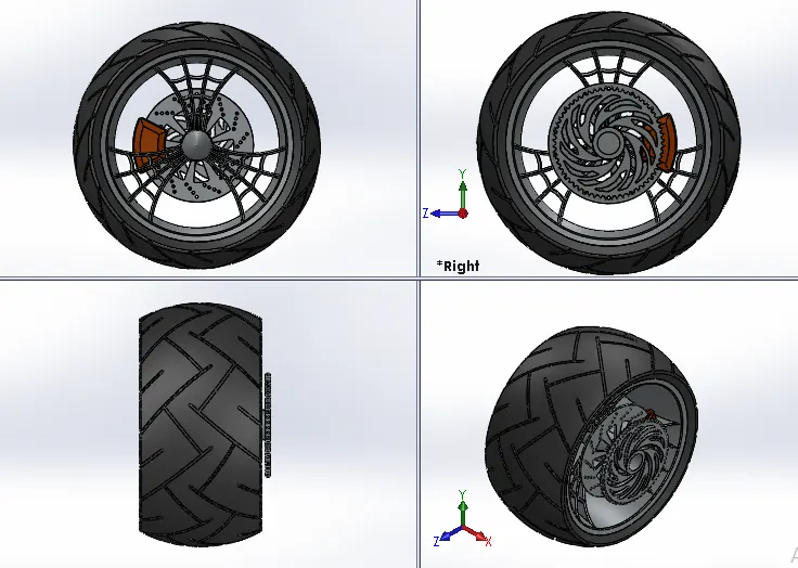
The rear wheel also houses a Disc brake rotor and its calliper and specifically a Chain sprocket to drive the wheel using power transmitted from engine. Rear wheels of choppers are generally smaller in diameter than the front wheel having a wide base as compared to the latter.
- OIL TANK
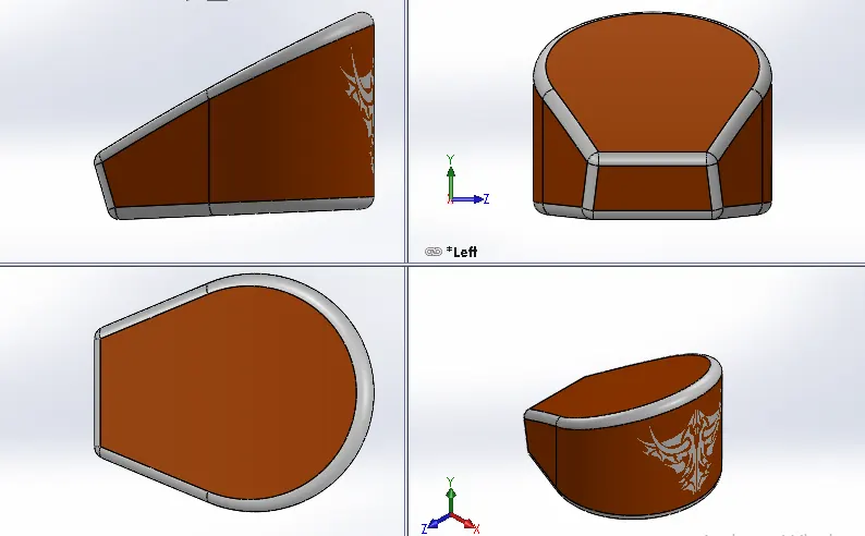
Oil tank is a component used to store the oil for lubrication and cooling purposes of engine components. Oil tanks can be of various kinds like engine oil tank, coolant oil tank, radiator oil tank etc. The oil tank used in this American chopper model is used for engine lubrication and cooling. This tank is placed right below the rider seat on top of the gearbox.
- GAS TANK/ FUEL TANK
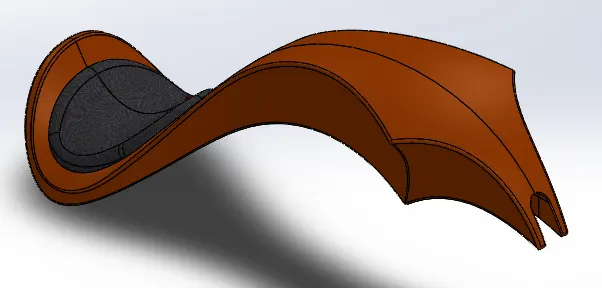
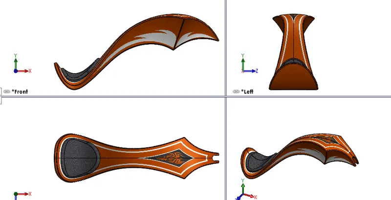
Fuel tank is the fuel storage component of the motorcycle. It is made to store flammable fluids or gas in a cool state away from the engine heat. Safety of the petrol is the main criteria in designing the fuel tank. It is connected to a fuel pump or a fuel regulator device such as carburettor or an injection system to supply appropriate amount to the engine with proper mixture of air and fuel. The fuel tank of this American chopper is made to house a seat and fit to the chassis centrally with the mount. It is made up of surfaces and finally these surfaces are knit together to form a complete solid body with hollow shell to store fuel.
- CHESSIS
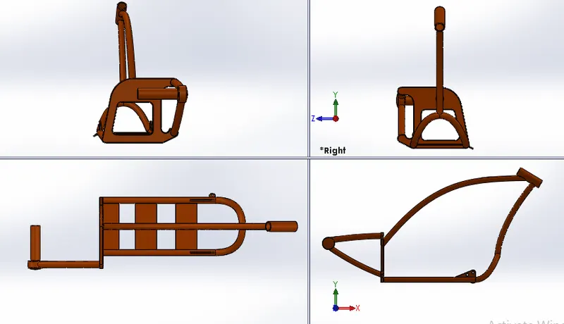
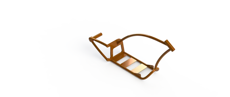
Chassis is the main strength component or the structural framework of any automobile. All components of the motorcycle are either directly or indirectly mounted to the chassis. The chassis has to be the strongest component of any vehicle as it is the base structure. The chassis should be made up of high strength material that can withstand variable compressive, tensile and shear stresses.
- ENGINE
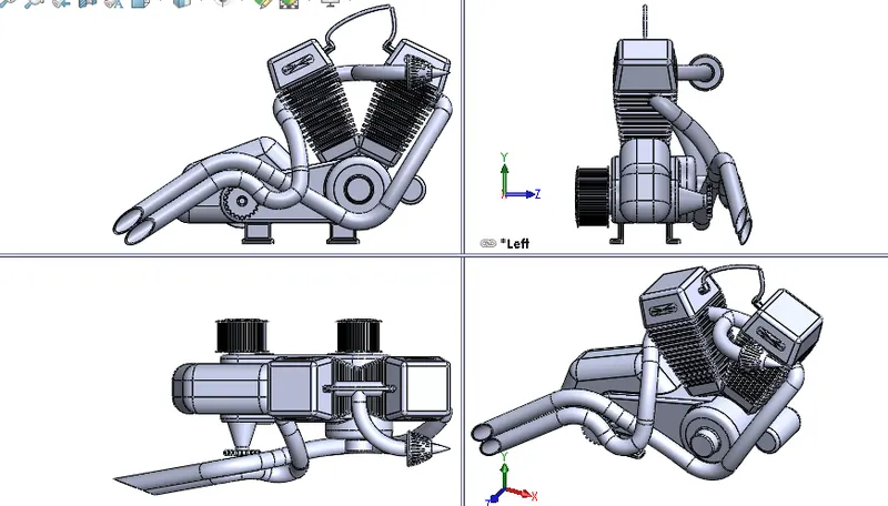
Engine is the main powerhouse of any automobile. The engine consists of piston-cylinder arrangement which powers the motorcycle. The IC engine houses air intake, exhaust outlet and fuel intake ports. This American chopper motorcycle has a V-Twin type engine consisting of external air filter, spark plugs 1 for each cylinder, transmission pulleys, air cooling fins, starter motor, front sprocket for chain drive, exhaust pipes and casing for sump and gearbox. It also consists of 4 mounting points to be mounted for the chassis.
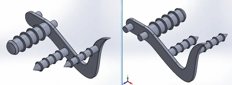
13. PEDAL
Helps in driver leg rest as well as the Gear and Brake lever operation ease.
MAKING FINAL ASSEMBLY
Basic Mates include,
- Coincide
- Parallel
- Perpendicular
- Concentric
- Width(Distance gap)
- Angled at
- Symmetric
So, just understanding the concept of fixation at particular placement the required mate is used.
Luckly, SOLIDWORKS Shows all the possible mates for the those parts which we select.
- Begin by Fixing the chassis position on the Front-Plane of the assembly coincident to Mid-Plane chassis.
- Later keep all the parts Mid-Plane to be in coincide with the chassis Mid-Plane using coincide mate option
- Give relation coincident Mid-Plane chassis and Front-Plane engine.
- Make the engine mounts coincident to the base plate of chassis and 20mm behind the vertical face of plate.
- Make the pedals concentric and coincident to the mounts and mirror the part appropriately.
- Use coincident, concentric and limit angle mates with kickstand and mount.
- Give relation coincident Mid-Plane chassis and Right plane rear wheel and make the axle hole concentric to the Hub axle on swing arm.
- Give relation parallel to right plane chassis and Front-Plane of rear wheel.
- Make rear fender concentric to rear wheel and give relation parallel to vertical plane Rear Fender and Right plane chassis.
- Give relation coincident to Mid-Plane chassis and Mid-Plane rear fender.
- Give width mates, concentric and angle mates to transmission belt on pulleys.
- Make oil tank coincident on gearbox face and give relation of coincident to Mid-Plane chassis and Mid-Plane of oil tank.
- Back edge of oil tank coincident to the edge of gearbox.
- Make front forks concentric to the steering stem and give width mates on the chassis, limit the rotation to 30° in both directions.
- Make a central position mate and suppress it.
- Use concentric and width mates for the chain with rear wheel, make its front centre coincident to the front sprocket sketch or apply appropriate angle mates if error occurs.
- Give parallel relations between Mid-Plane chain and Mid-Plane chassis; parallel relation between Bottom plane chassis and centre plane chain.
- Make bottom plane FT coincident to plane created in chassis.
- Make Mid-Plane FT and Mid-Plane Chassis coincident.
- Give a distance mate of 5mm for Front-Plane FT from plane 1 in chassis.
- Give relation coincident to Mid-Plane forks and right plane front wheel.
- Make the axle concentric to axle hole.
- Use coincident relations to straighten the front wheel with respect to the front forks.
- Make the front wheel, rear wheel and the kickstand tangent to the top plane of the assembly to give it a rest position.
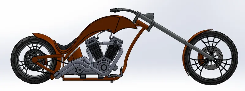 SIDE VIEW
 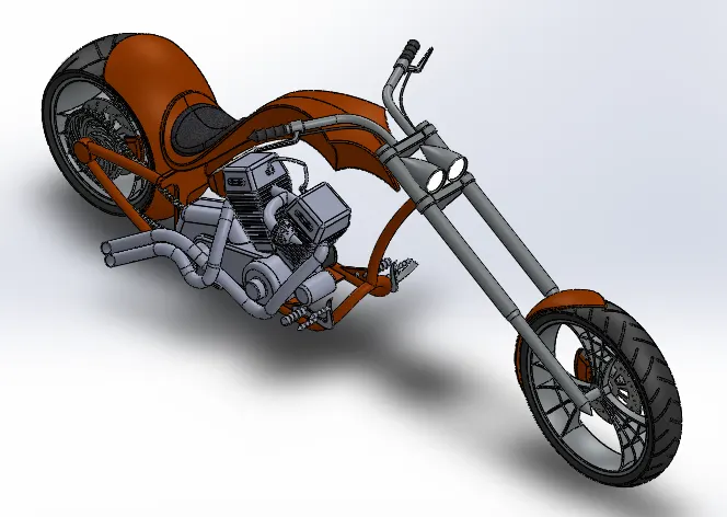 ISOMETRIC VIEW
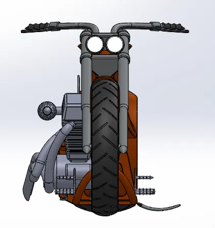 FRONT VIEW
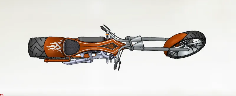 TOP VIEW
Finally, Save the assembly..!
PHOTOREALISTIC RENDERING
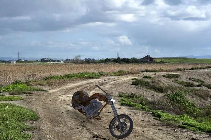
Rendering of the assembly is done to make a good quality 2D images for the purpose of advertising and promotion of the products before selling it to the customers. Photorealistic rendering creates high quality images or motion graphics if available so as to look appealing in various environments and backdrops.
SOLIDWORKS provides 2 rendering products:
Photoview 360 which is inbuilt add-in for SOLIDWORKS
SOLIDWORKS Visualize which is a separate Render Engine.
PHOTOVIEW360
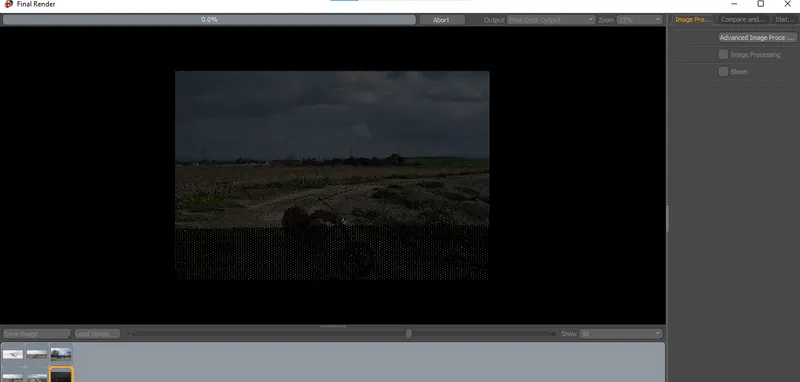
After adding photoview 360 the render tools tab can be brought in
It has various options like preview window, render region, final render, edit appearance, edit scenes, and options for managing render quality, Bloom, cartoon, direct caustics, network rendering and final image type.
Schedule render and recall last renders are also some options.
Decals can be added using edit decals, image can be added on faces by mapping values in coordinate directions. Illumination can be set to underlying appearance for better blending of decals.
Display states can be set for parts individually so as to provide multiple appearances to a single part and changing the appearance whenever required.
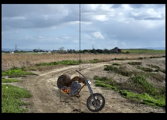
From view dropdown- Lights and camera is for setting up camera views and lighting of the scenes.
 (NO DECAL)
 (WITH DECAL)_CAMERA VIEW
SOLIDWORKS VISUALIZE
SOLIDWORKS Visualize provides a suite of standalone software tools that combine industry-leading rendering capabilities with visual design-oriented features and workflows, allowing easy and fast creation of visual content that communicates a design’s vision, passion, and emotion.
It is a separate render engine that is provided under SOLIDWORKS professional.
Visualize Professional adds an array of features including animations, custom lighting, VR, 360 Interactive, and much more.
SOLIDWORKS Visualize Professional provides the highest level of detail and optimized render times.
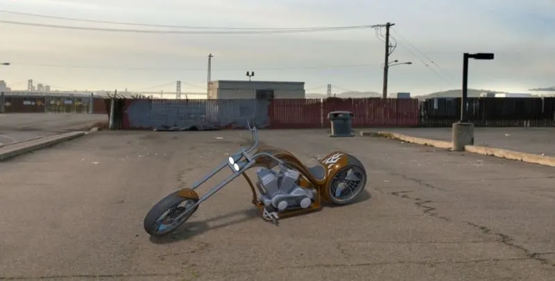
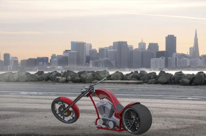
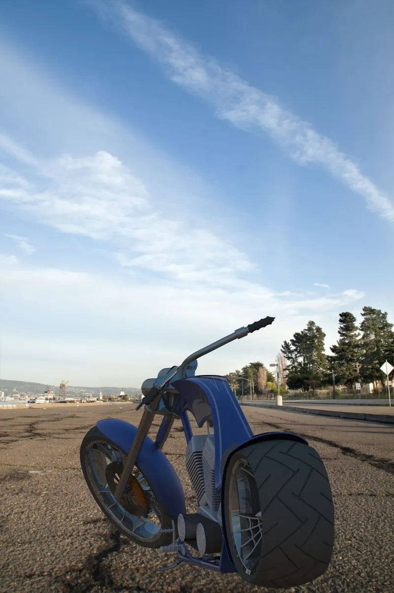
It helps in creating Rendered images of the SOLIDWORKS models in Photorealistic environments for marketing quality images with various options to tweak on the final image required as per the user.
It uses either of the CPU or GPU or both as hybrid to render quality images
Import the assembly and select part grouping as appearance, this ensures that all the parts having same appearance are grouped together in appearance tab.
All parts having same appearance can be tweaked together using appearance options.
Setting up of background can be done from scenes tab which includes a wide range of HDR images and backgrounds.
Background brightness, rotation, gamma can be changes as required from the scenes tab.
Camera views can be added or used from assembly.
Render output image properties can be changed from output tools. Things such as image size, animation, photograph scenes, usage of CPU, GPU or both as hybrid can be selected.
CONCUSION
Design, Assembly and Photorealistic rendering using SOLIDWORKS was successfully completed.