Photo Realistic Rendering
Assembly of Chopper Model
Objective:
- To render the chopper model by adding appearances, decals, lights, cameras, and background scenes in photoview 360 and solidworks visualize.
Part design: The following are parts of american chopper we design using solidworks
- Transmission belt
- Kick stand
- Front fender
- Rear fender
- Oil tank
- Chain
- Pedal
- Front wheel
- Rear wheel
- Front fork
- Chassis
- Engine
- Gas tank
features used mostly in solidworks design are as follows
extrude: used to give thickness to a 2d sketch with reference to a plane or surface or vertex etc
revolve : is used to convert the sketch into 3d object/solid with reference to an axis selected.
split: is used to trim off a part from the selected solid.here it is used to obtain the curvature at both the ends
fillet: is used in to make sure that no pointing edges are present and to obtain a smooth transistion between two or more faces.
convert entities: is a sketch entity used to bring the edges of a solid or previous sketches to current sketch for them to be used as reference.
shell: The shell tool hollows out a part, leaves open the faces you select, and creates thin-walled features on the remaining faces.
Transmission belt: it transfers the power from engine to gearbox
features used in designing :
sketch tools- line, 3 point arc, offset entities
features- extrude, fillet
procedure of designing transmission belt:
- we draw the 2d sketch as show below using tools/entities such as line, arc, offset entities and give the m the appropriate dismensions to make sketch fully constrained
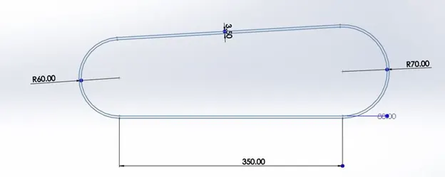
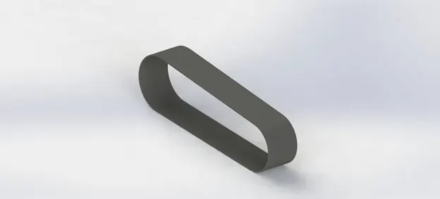
Extruded the above sketch for a distance of 88mm to get the belt.
Matte Rubber was assigned as material for the belt.
kick stand: used to support bike while in parking
tools used:
- Sketch
- Loft
- Dome
- Extrude boss
- Extrude cut
- Fillet
- Split
- Appearances
procedure of design of kick stand:
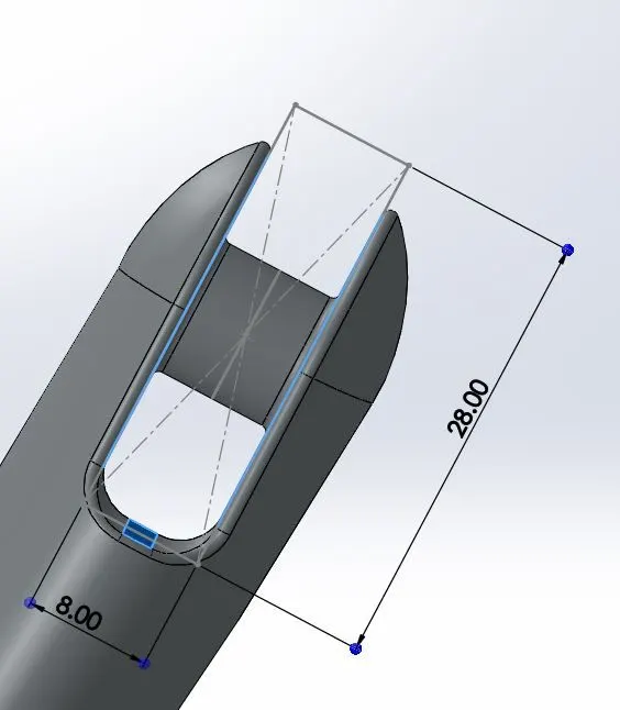
Sketch is drawn as shown below by using sketch entities such as elicpse and spline and dimensioned using smart dimension tool to make the sketch constrained.
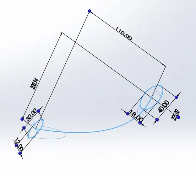
The loft command is used for which the two profiles are the two ellipse at the end of the spline. The spline acts as a guiding curve for the profile
3D model
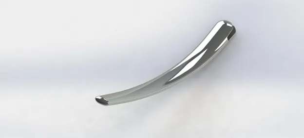
Additional cut for the kickstand was given at the pivoting point where it is attached to the chassis of the chopper
Front fender: The front fender is mounted on a above the front wheel, which is used to protect rider and chopper other parts from dust, mud and other particles.
tools used:
- Sketch
- Offset entities
- Trim entities
- Revolve
- Dynamic mirror
- Split
- Fillet
- Appearance
procedure of designing front fender:
- sketch is drawn using 3 point arc, offset entities, line to obtain a closed figure as shown below and it is dimensioned with reference to origin to make it constrained which then used to revolve to get 3d solid.
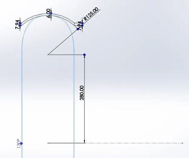
Revolve command is used in which 5 degrees for direction 1 and 130 degrees was used for direction 2.
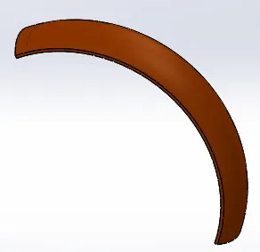
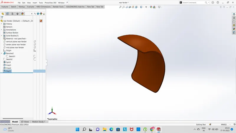
rear fender: placed on above the rear wheel, it acts as housing to the wheel.
tools used :
- Sketch
- Offset entities
- Trim entities
- Revolve
- split
- fillet
- Apperance
sketch : in sketch workbench using arc, offset entities, trim entities we draw a closed figure as show below and dimension it with respect to orgin to abtain a fully constrained figure.
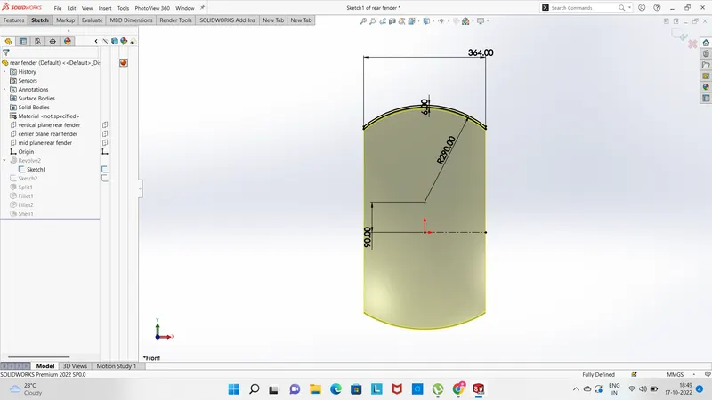
- revolveis used to convert the sketch into 3d object/solid with reference to an axis selected.
- split: is used to trim off a part from the selected solid.here it is used to obtain the curvature at both the ends
- fillet: is used in to make sure that no pointing edges are present and to obtain a smooth transistion between two or more faces.
- apperance : siena apperance is given given to the fender in this instance
3D MODEL
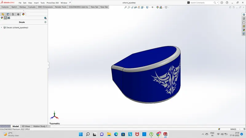
Oil tank: it stores the engine oil which is circulated through the engine and its parts with relative motion to provide lubrication
tools used:
- Sketch
- Boss extrude
- Combine
- Shell
- Fillet
- Appearance
procedure:
- First open solid works then select new part to create new model
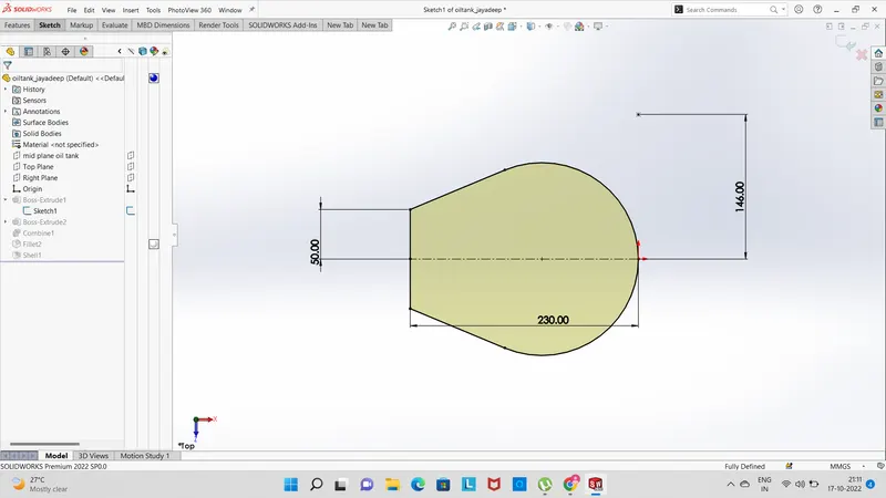
- Then change front plane into midplane oil tank and select top plane for sketching
- Then draw 2D sketches by using sketch commands, then add dimensions and relations as we required for fully defined the sketch, then combine the model.
- Then do shell and fillet commands and change the appearances and save the model.
3D MODEL:
Chain: is used to transmit the power from transmission to rear wheel.
here intially we draw the inner plate and outer plate of chain in sketch workbench and save them as blocks so that we can use them individually at any time needed.
then we draw the sketch as shown below using curves to obtain the shape of chain . to which we align the chain plate blocks
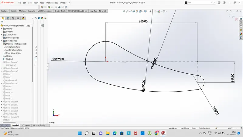
sketch for resemblance of chain layout
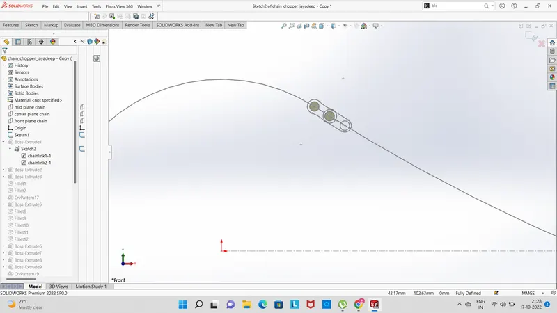
assigning the chain plates using 'insert block' option
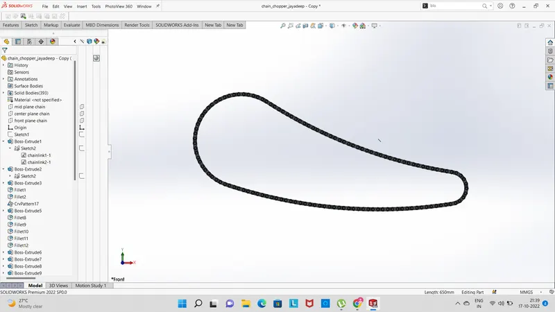
then we extrude the chain plates and do a curve pattern to obtain the chain by ensuring that the centers of chain plates are always coinciding the sketch
once we complete the circular pattern all over the sketch we can mirror using the mid plane to form the otherside of the chain
3D MODEL:
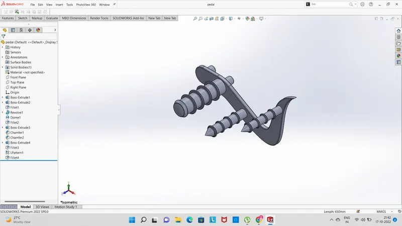
Pedal: The main purpose of pedal is that place the leg on top of that for resting position and some times used for changing the gears by keeping leg on pedal.
Features used to create a chain:
- Sketch
- Boss extrude
- Revolve
- Dome
- Fillet
- Chamfer
- Linear pattern curve
- Appearance
procedure:
- First open solid works then select new part to create new model
- Then select front plane for 2D sketch.
- Then draw all 2D sketches by using sketch commands, and add dimensions and relations as per required for fully defined the sketch.
- Then apply dome, fillet and chamfer commands to sketch.
Then add linear pattern curve for sketch and change the appearance of sketch
3D MODEL:
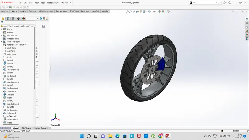
Front wheel: Motorcycle wheels are made to cope with radial and axial forces. They also provide a way of mounting other critical components such as the brakes, final drive and suspension. Wheels, and anything directly connected to them, are considered to be unsprang mass. Traditionally motorcycles used wire-spoked wheels with inner tubes and pneumatic tyres.
Features used to create a Front wheel:
- Sketch
- Revolve
- Boss extrude
- Cut extrude
- Circular pattern
- Linear pattern
- Combine
- Trim
- Fillet
- Chamfer
- Appearance
Procedure:
- First open solid works then select new part to create new model
- Then select front plane for 2D sketch.
- Then draw all 2D sketches by using sketch commands, and add dimensions and relations as per required for fully defined the sketch.
- Then apply linear pattern, circular pattern, fillet, chamfer combine commands to sketch.
- Then change the appearance of front wheel.
3D MODEL:
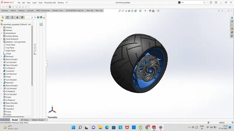
Rear wheel: a sprocket is mounted to the rear wheel to which the chain is assembled for the rear wheel to be driven by the power from transmission.
Features used to create a Rear wheel:
- Sketch
- Revolve
- Cut extrude
- Boss extrude
- Circular pattern
- Combine
- Revolve cut
- Fillet
- Chamfer
- Appearance
Procedure:
- First open solid works then select new part to create new model
- Then select front plane for 2D sketch.
- Then draw all 2D sketches by using sketch commands, and add dimensions and relations as per required for fully defined the sketch.
- Then apply linear pattern, circular pattern, fillet, chamfer combine commands to sketch.
- Then change the appearance of rear wheel, caliper, rim,rotor
3D MODEL:
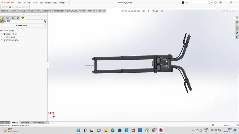
Front fork: The front fork prevents excessive weight on the front wheel during drastic sudden applications the break, softens bumping when driving on rough road surfaces. The front fork maintains proper damping through traction with the road surface.
Features used to create a Front fork:
- Sketch
- Revolve
- Boss extrude
- Fillet
- Linear pattern
- Cut extrude
- Dome
- Revolve cut
- Project curve
- Mirror
- Combine
- Sweep
- Split
procedure:
- First open solid works then select new part to create new model
- Then select front plane for 2D sketch.
- Then draw all 2D sketches by using sketch commands, and add dimensions and relations as per required for fully defined the sketch.
- Then mirror the object and change the appearance of object.
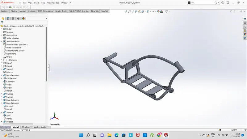
chassis: it is the base of any vehicle to which all the parts are mounted . it should designed considering all the loads acting on it which may cause deformation. hence it shoyuld be designed in a way to withstand all the loads
Features used to create a Chassis:
- Sketch
- Convert entities
- Project curve
- Offset
- Trim
- Sweep
- Split
- Revolve
- Cut extrude
- Fillet
- Combine
- Mirror
- Chamfer
- Dome
procedure:
1. First open solid works then select new part to create new model
2. Then change the default names of planes as
Front plane in to Midplane chassis
Top plane in to bottom plane chassis
3. Then select midplane chassis for sketch then bring the sketch picture in the midplane chassis and then change the x and y directions positions and transparency as per required.
4. Then exist the sketch and rename the sketch as blueprint chopper.
5. Then draw the 2D sketches by using planes, and sketch commands and give dimensions and relations as per required to fully defined the sketch.
6. Then change the appearance of chassis and save the model.
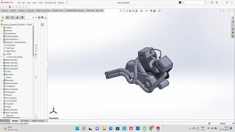
engine: engine is the one which produces the power to propell automobile . it converts the chemical energy into mechanical energy by means of combustion pushing down the piston which is linear motion which is converted into rotary motion by the crank which is transfered to the wheels.
tools used
- Sketch
- Boss extrude
- Revolve
- Fillet
- Circular pattern
- Dome
- Cut extrude
- Chamfer
- Linear pattern
- Mirror
- Swept
- Project curve
- Split
procedure:
- First open solid works then select new part to create new model
- Then select front plane for sketch and then bring the sketch picture in the midplane chassis and then change the x and y directions positions and transparency as per required.
- Then exist the sketch and rename sketch in to blueprint chopper.
- Then draw the 2D sketches by using planes, and sketch commands and give dimensions and relations as per required to fully defined the sketch.
- Then change the appearance of Engine and save the model.
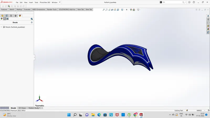
gas tank : commonly fuel tank used for storing of fuel and supply to engine through pump for injectors or by force of gravity to carburetor.
Features used to create a Gas tank:
- Sketch
- Surface sweep
- Surface trim
- Project curve
- Surface loft
- Surface boundary
- Surface knit
- Split line
- Mirror
- Surface extrude
- Fillet
- Cut sweep
- Shell
procedure:
1. First open solid works then select new part to create new model.
2.Then change the default names of planes as
Front plane in to Midplane fuel tank
Top plane in to bottom plane fuel tank
Right plane in to front plane fuel tank
3. Then select midplane fuel tank for sketch, then bring the sketch picture in the midplane fuel tank and then change x & y directions positions and transparency as per required.
4. Then exist the sketch and rename sketch in to under lay fuel tank.
5. Then draw the 2D sketches by using planes, and sketch commands and give dimensions and relations as per required to fully defined the sketch.
6. Then change the appearance of Gas tank and save the model.
some common errors during part designs are :
- when drawing sketch or dimensioning sometimes it shows overdefined it may be because of accidental application of relation with other geomentry in the part.
- sometimes we may give dimension of a entity with respect to other reference entity instead of actual entity which cause geometrical errors .same wil be extruded on features.
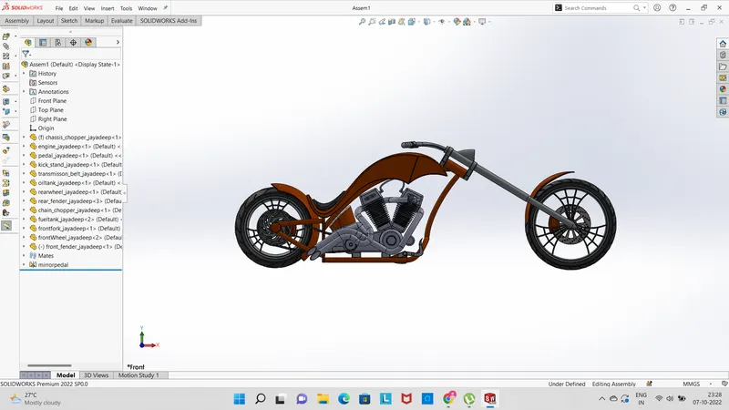
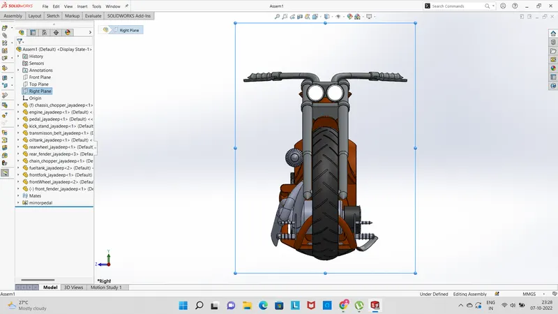
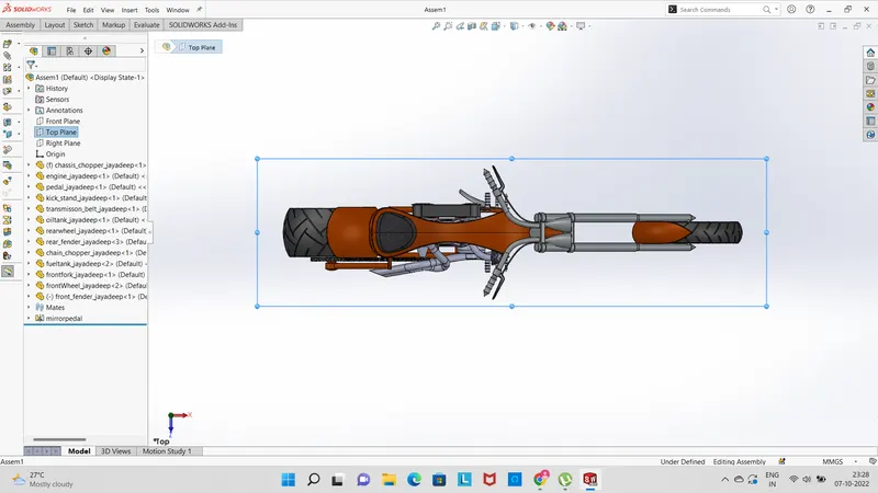
ASSEMBLY:
- We assemble all the parts designed together in order to render them to make sure how they look in real time
- in assembly we have two important basic features 'import part' and 'mates'
- import part is used to import the part to be assembled into the assemble work bench
- mates are used to mate the parts with respect to each other
- there are different types of mates such as basic mates i.e standardmates, advancemates etc
- standard mates uses relations like cocentric , coincident, parallel,perpenduclar,tanget etc
- advanced mates contains features like distancemate, widthmate,angle mate etc
- we use all this mates to mount all the parts we designed together
- firstly we import chassis and fix that in assembly workbench
- then all the other parts are mated with respect to chassis to make sure that the move along with chassis when floated
- different types of mates basing on situations are used
- once assembly is completed we can save and zip all the parts together inorder to acess them easily.
FRONT VIEW:
RIGHT SIDE VIEW:
TOP VIEW:
ISOMETRIC VIEW: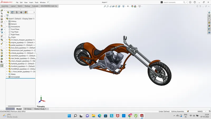
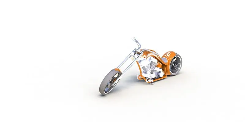
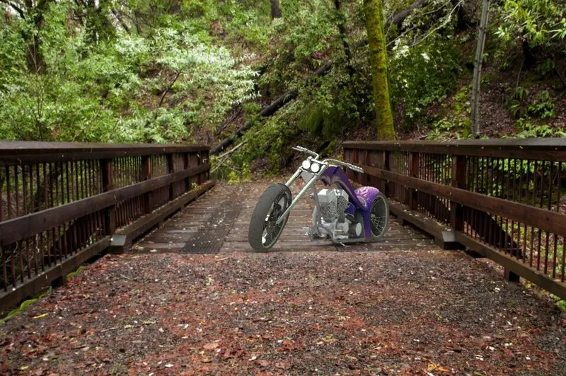
PHOTOREALISTIC RENDERING: The purpose isto give the realisticness to our part by creating scenes ,environments, adding decals , cameras, lights are part of this.This can be done in photo view 360 or solidworks visualize.
rendering of chopper:
CONCLUSION: We designed the american chopper using solidworks.