Photo Realistic Rendering
Project Report:
INTRODUCTION:
SOLIDWORKS have different software that are used by mechanical, electrical, civil etc engineering branches. Here we use SOLIDWORKS CAD modeling software which use for 3D and surface designing, plastic and mold designing, photo realistic rendering, FEA analysis etc.
In this project we do solid and surface modeling for designing of parts and then these parts where assemble together in solid work software
Commands Used very frequently and most handy operations in the solid works:
- OBJECTIVES
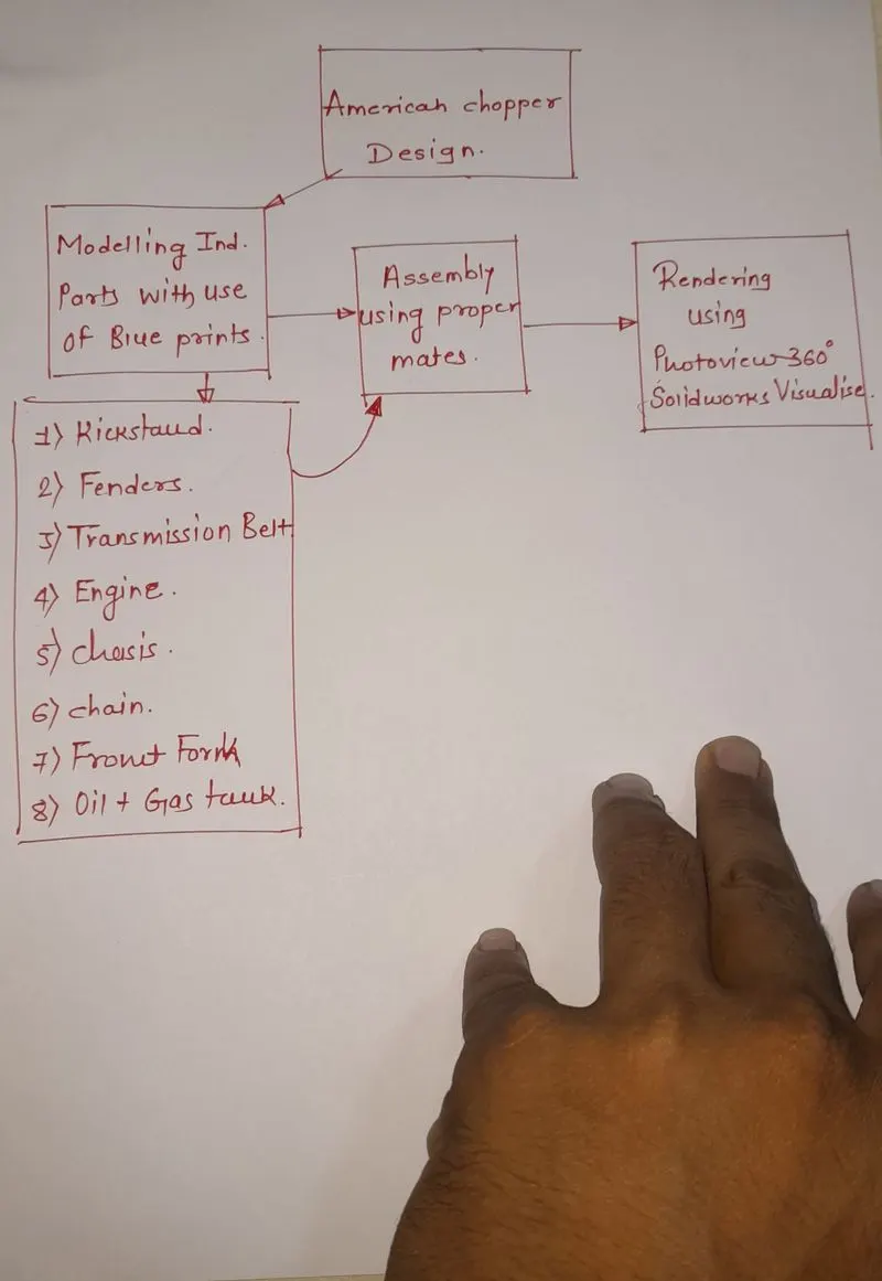
- Learn the basic features and tools of the SOLIDWORKS Model the different parts of American Chopper
- Assemble the part models of American Chopper
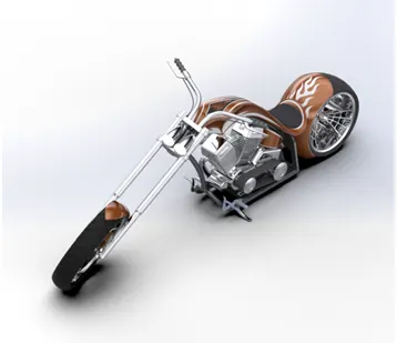
- Using PHOTOVIEW 360 perform a photo realistic rendering of an American Chopper
FLOWCHART:
Extrude Boss:
This is one of the most common and universal features used within the 3D modeling world. This is a handy feature for creating 3D solid models within SOLIDWORKS. Using the modeled 2D sketch created, you are ready to turn the 2D sketch element into a 3D solid feature.
Fillet:
Fillet creates a rounded internal or external face on the part. You can fillet all edges of a face, selected sets of faces, selected edges, or edge loops.
Revolved boss feature
Revolved boss feature add or remove material by revolving one or more profiles around a centerline. You can create revolved boss/bases, revolved cuts, or revolved surfaces. The revolve feature can be a solid, a thin feature, or a surface.
Extrude cut:
Using the Extruded Boss/Base model created in the Extrude boss base blog, we will modify the 3D block to include a circle feature by removing material. The Extruded Cut feature can be found on the features tab in the Command Manager interface
The Cut-Extrude feature is a very useful tool. In the manufacturing world, it can be a common practice to start with stock material and proceed to use the Cut-Extrude tool to remove material as you would during the machining phase.
Shell:
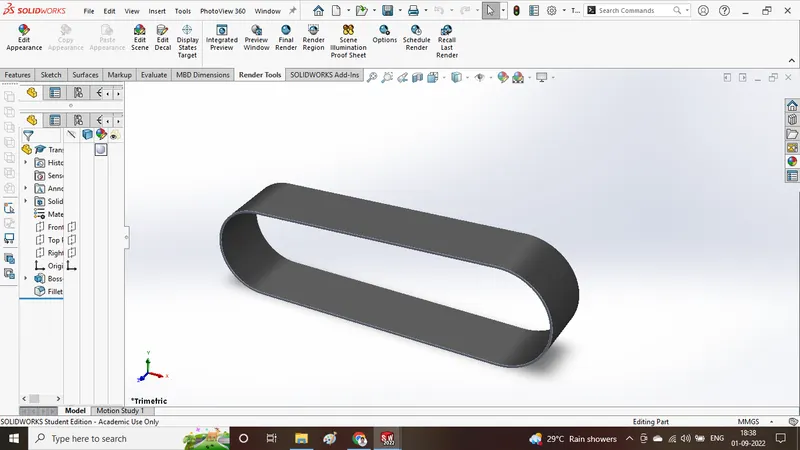
The shell tool hollows out a part, leaves open the faces you select, and creates thin-walled features on the remaining faces.
If you do not select any face on the model, you can shell a solid part, creating a closed, hollow model. You can also shell a model using multiple thicknesses. If the Shell tool has problems shelling a model, the Error Diagnostics section appears in the Property Manager to help you diagnose the problem.
Sweep boss/ sweep cut
Sweep is the one feature in SOLIDWORKS that helps sweep a closed profile along a closed or open path. In this session, we are going to use a simple 3d object as an exercise to demonstrate the use of the SWEEP command in SOLIDWORKS.
The most common usage is in creating cuts around cylindrical bodies. This option would also be useful for end mill simulation. When you select Solid Sweep, the path must be tangent within itself and begin at a point on or within the tool body profile.
Loft boss/ loft cut
The loft feature is an important tool for modeling in SOLIDWORKS. The loft feature creates a shape by making transitions between multiple profiles and guide curves. This tool is very valuable for modeling complex surfaces. You can do some really cool stuff when you use this feature properly.
Loft creates a feature by making transitions between profiles. A loft can be a base, boss, cut, or surface. You create a loft using two or more profiles. Only the first, last, or first and last profiles can be points. All sketch entities, including guide curves and profiles, can be contained in a single 3D sketch.
Linear pattern:
The SOLIDWORKS Linear Pattern tool is a great way to make a grid of holes or multiple bodies very quickly. This tool is very easy to use and saves you a lot of time. Use linear patterns to create multiple instances of one or more features that you can space uniformly along one or two linear paths.
Mirror:
Mirroring is another way that SOLIDWORKS can create a copy of an existing object. In most cases, you will have to create your own plane to have the mirror done the way you need.
Various commands are available for mirroring and creating opposite-hand versions of items such as sketch entities, features, parts, and assembly components. The command you need depends on the type of item for which you want to create a mirror or an opposite-hand version.
Projected curve:
SOLIDWORKS has a tool called Projected Curve that can take any sketch and transfer it over to another sketch or face. You can then use that sketch for creating features to even to split a body.
The Project Curve feature is more like the Split Line than the Wrap feature. It can do everything the Split Line feature with one exception, it gives up the ability to split faces in favor of being able to use open contour sketches that are within the boundary of a face.
Reference geometry:
Reference geometry defines the shape or form of a surface or a solid. Reference geometry includes items such as planes, axes, coordinate systems, and points.
You can use reference geometry in the creation of several kinds of features. For example:
- Planes are used in lofts and sweeps.
- An axis is used in a circular pattern.
COMBINE:
In a multi body part, you can combine multiple solid bodies to create a single-bodied part or another multi body part. You can add or subtract bodies, or keep material that is common to the selected bodies.
- Combining Bodies - Add:
In a multi body part, you can combine multiple bodies to create a single body. - Combining Bodies - Subtract:
In a multi body part, you can subtract one or more bodies from another body.
- Combining Bodies - Common:
In a multi body part, you can create a body defined by the intersection of multiple bodies. - Combine Property Manager:
In the Combine Property Manager, you specify which bodies in a multi body part to add, subtract, or overlap.
DOME:
SOLIDWORKS provides a tool called ad ‘Dome’ that you can create domes on 3D parts and shapes. The use of dome command is very easy.
The Parameters in the dome Property Manager includes Faces to dome. Select one or more planar or non-planar faces. You can apply domes to faces in which centroid lies outside the face. This allows you to apply domes to irregularly shaped contours
Split:
Use the Split feature to create multiple parts from an existing part. You can create separate part files, and form an assembly from the new parts.
You can split one or more solid or surface bodies. To split a surface, the Trimming Surface must extend past the boundaries of the surface to split.
Mate:
Mates create geometric relationships between assembly components. As you add mates, you define the allowable directions of linear or rotational motion of the components. You can move a component within its degrees of freedom, visualizing the assembly's behavior.
Circular pattern:
Circular pattern is to create multiple instances of one or more features that you can space uniformly around an axis. You can create circular patterns symmetrically or asymmetrically in both directions from the seed geometry. This is useful when the seed is not located at the end of the pattern arc. The Circular Pattern Property Manager appears when you pattern one or more features around an axis.
Sketch driven pattern:
Using sketch points within a sketch, you can specify a feature pattern. The seed feature propagates throughout the pattern to each point in the sketch. You can use sketch driven patterns for holes or other feature instances.
Sketch driven pattern creates the pattern using only the geometry of the features, rather than patterning and solving each instance of the features. The Geometry Pattern option speeds up the creation and rebuilding of the pattern. You cannot create geometry patterns of features that have faces merged with the rest of the part.
Chamfer:
The chamfer tool creates a beveled feature on selected edges, faces, or a vertex. You can create partial chamfers for offset face chamfers by specifying lengths along model edges
Helix/Spiral:
You can create a helix or spiral curve in a part. The curve can be used as a path or guide curve for a swept feature, or a guide curve for a lofted feature. The diameter of the circle controls the starting diameter of the helix or spiral.
Delete face:
You can delete faces from surface and solid bodies.
With Delete Face tool, you can do the following:
Show selection toolbar:
Shows/hides selection accelerator toolbars
Delete:
Deletes a face from a surface body, or deletes one or more faces from a solid body to create surfaces.
Delete and Patch:
Deletes a face from a surface body or solid body and automatically patches and trims the body.
Delete and Fill:
Deletes faces and generates a single face to close any gap.
Surface extrude:
We can create extruded surfaces from models that include 2D or 3D faces and knit the extruded surfaces to surrounding features. And can extruded surface at one end or at both ends
Filled surface:
The Filled Surface feature constructs a surface patch with any number of sides, within a boundary defined by existing model edges, sketches, or curves, including composite curves.
Surface trim:
We can use a surface, plane, or sketch as a trim tool to trim intersecting surfaces. We can also use a surface in conjunction with additional surfaces, as mutual trim tools. Trim surface includes the following options
Surface extend:
You can extend a surface by selecting an edge, multiple edges, or a face. For edges, the surface extends along the plane of the edge. For faces, the surface extends along all edges of the face except those connected to another face.
Surface sweep:
You can select faces, edges, and curves directly from models as sweep profiles. The profile may be open or closed for a surface sweep feature. The path can be open or closed, and can be a set of sketched curves contained in one sketch, a curve, or a set of model edges. The start point of the path must lie on the plane of the profile.
Surface offset:
A common technique for advanced surfacing modeling is using the surface offset command. The command gives users the option to see and remove any surfaces that cannot be offset, building the remaining geometry.
Ruled surface:
The Ruled Surface command creates surfaces that extend out in a specified direction from selected edges.
Examples of how you can use ruled surfaces:
- Add tangent extensions to complex surfaces
- Create drafted sidewalls
- Replace non-drafted surfaces on imported models with drafted surfaces
- Create parting and interlock surfaces
- Surface knit:
The Knit Surface tool is to combine two or more faces and surfaces into one. When you knit surfaces to within a tolerance and the distance between two surface edges exceeds the tolerance, the resulting knitting gaps are considered open. In the Knit Surface Property Manager, under Gap Control, you can modify the knitting tolerance to improve the surface knit, based on resulting gaps.
Surface loft:
The loft feature in solid works allows you generate complex geometry in a single feature. It does this by interpolating surfaces between various cross-sections of a model. These cross-sections can be sketches, faces, or edges. In the loft interface, these cross-sections are considered “Loft Profiles”. Because this solid works tool is interpolating surfaces to create geometry, it can be difficult to control the loft enough to produce the desired geometry. Here are some tips and tricks for using the Loft feature
Thicken surface:
Thicken takes a surface body and makes it a solid by specifying a thickness value and side to thicken. Until now, the calculation was based on surface normal, which is often what you want. Now, though, we can specify a direction for the offset created by the thicken command.
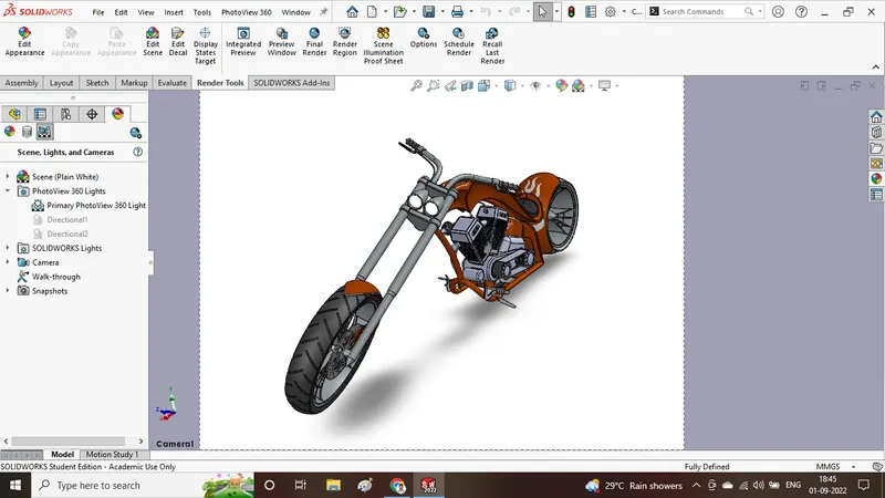
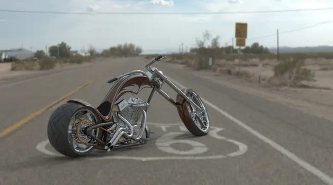
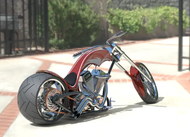
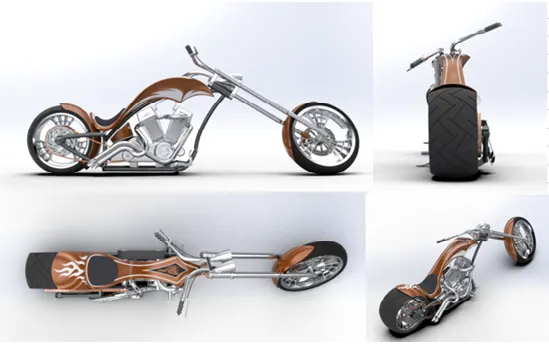
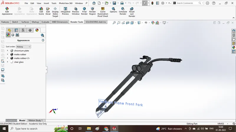
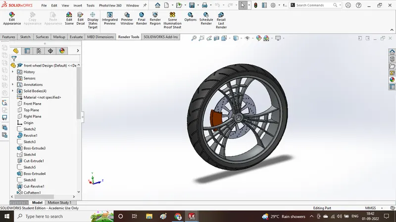
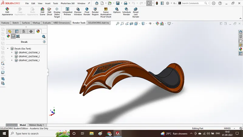
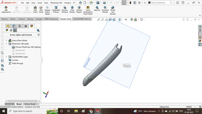
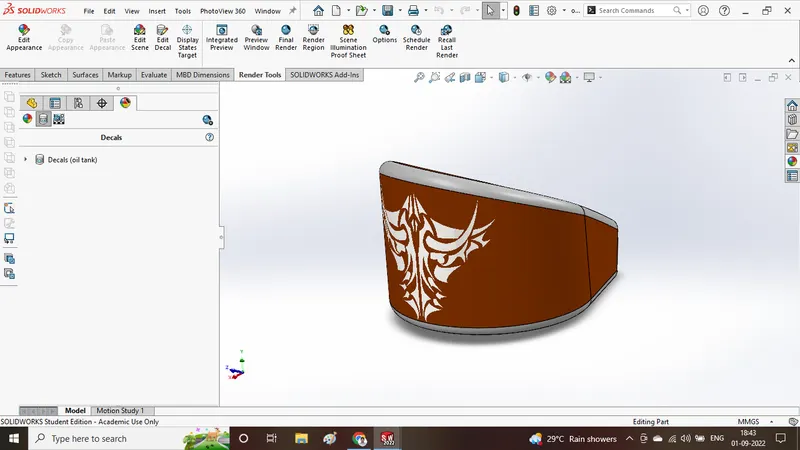
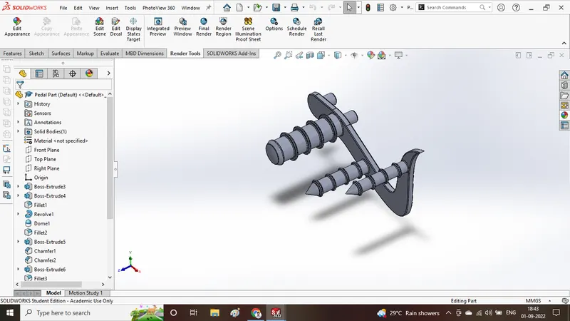
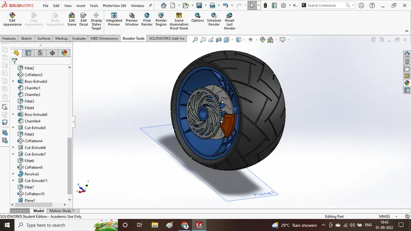
SNAPS OF REALISTIC RENDERING OF AMERICAN CHOPPER.
CAMERA VIEW:
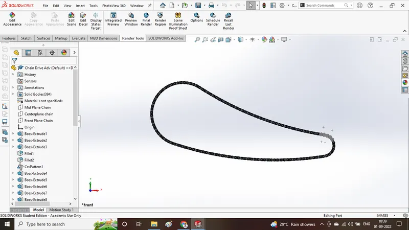
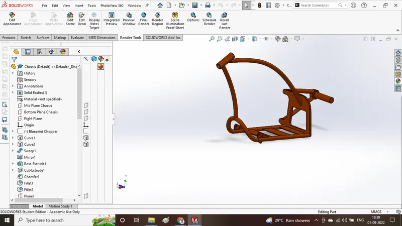
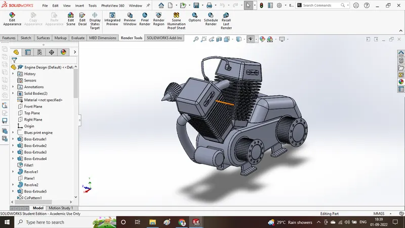
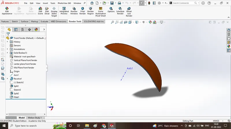
CONCLUSSION
- The parts are sketched and modelled in the SOLDWORKS.
- The modelled parts are assembled with possible mates in to the main assembly of American chopper.
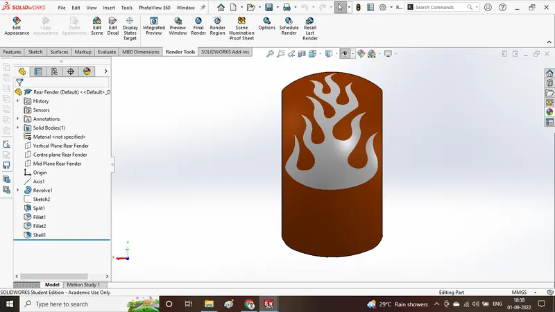
- The decals are applied to faces of parts.
- The realistic images was rendered with use of both ways “Photoview 360 and Solidworks Visualize