Photo Realistic Rendering
Objective:
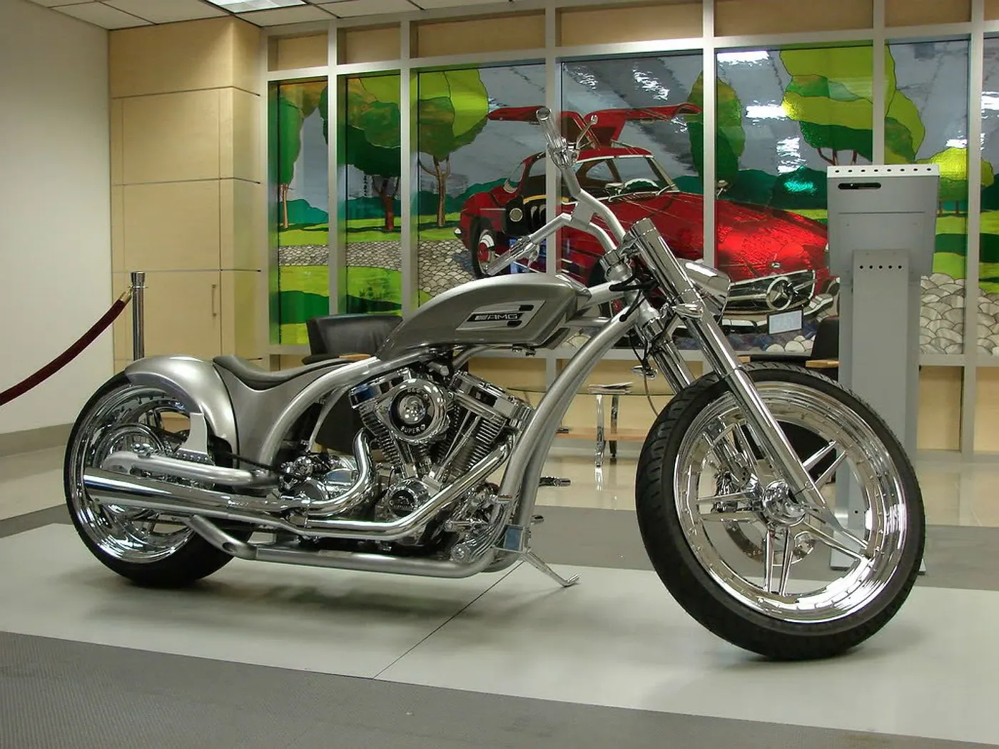
- The Objective of this project is to re-create the American Classic with the use of technology at our disposal.
- We would be creating all the individual parts like wheels, chassis, tank etc with the use of SOLIDWORKS.
- Post creation of parts they would be assembled with the use of Assembly feature within SOLIDWORKS.
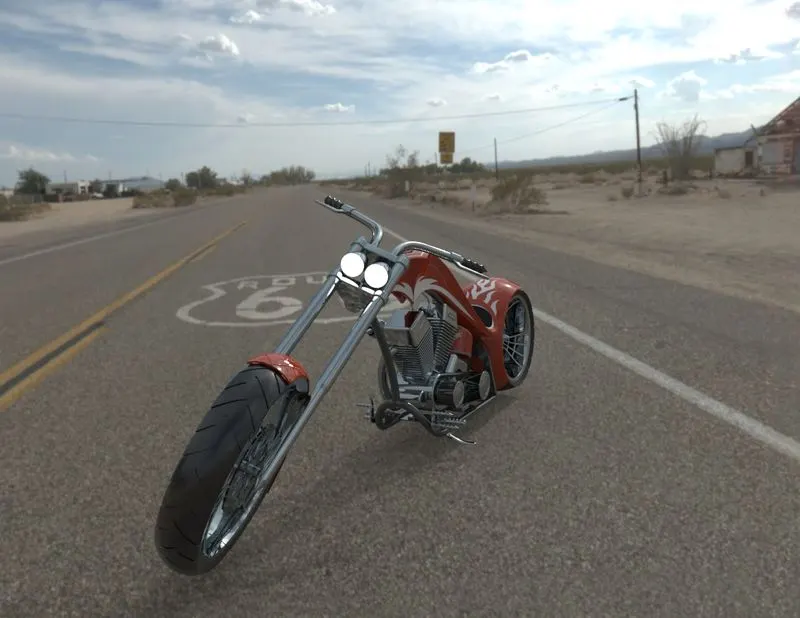
- Finally we would be using PHOTVIEW360 to apply proper aesthetics like Lights, Camera, Background environment, Backdrop lights, Shadows etc. in accordance to real world scenarios.
Introduction:
- The American Chopper is a classic of our generation.
- They have influenced our society and culture on a large scale.
- The chopper symbolizes both power and style.
- They have been in existence since the 1950’s but it has not passed into history.
- The characteristic features of choppers are long front forks often coupled with an increased rake angle, hardtail frames, very tall or very short handlebars, stretched frames, large rear wheels and relatively slim front wheels.
METHODOLOGY
Parts Creation:
SOLIDWORKS interface offers us a variety of features in order to create the desired model. Below mentioned is a short description of the tools used to create parts for the American Chopper under the tab SKETCH.
- Line/Centre Line: As the name suggest we are able to create Lines using this tool both for creation of the model and creating references.
- Circle: We can create a circle with the use of a centre point/ radius or we can use the perimeter.
- Rectangle: We can create a rectangle with the use of different options corner rectangle, centre point rectangle, 3point corner rectangle, point centre rectangle and a parallelogram.
- Slots: We have different types of slots but in our model, there is straight slot, centre point straight slot, 3point arc slot and centre point arc slot. We only make use of straight slot.
- Arc: We use this tool quite often in our model creation. There is 3point arc, centre point arc and tangent arc.
- Spline: This is an important tool in our arsenal towards the model creation. We have made use of only spline however there also is equation driven spline and Style spline.
- Fillet: This is a tool heling us to smooth out edges/corners. We make use of fillet and Chamfer.
- Trim Entities: This tool helps us in the removal of any excess material. There is also an option to extend part to the next sketch.
- Convert Entities: The tool helps us to bring a sketch made on different plane into the current sketch. There is also an option to use intersection curve which is used for spherical/rolled models.
- Offset entities: The tool helps us to create the same sketch but at an offset from the diagram.
- Mirror: The tool helps us to copy the sketch along an axis.
- Linear/ Circular Pattern: The tool helps us to copy the diagram in a linear or circular fashion.
- Smart Dimension: We can define dimension of our diagram with the use of this tool.
- Add Relation: The tool helps us decide whether our sketch has been defined completely. A fully defined sketch is always best.
- Sketch Picture: We can bring in a picture for reference from Tool Sketch tools Sketch Picture.
- Block: This tool helps us define a sketch as a block and hence forth allow us to insert the same in different sketches.
The Other feature used is the Features/Surface Tab. This where we define the thickness of the design to generate the model.
- Extrude Boss: We can provide instant thickness to any contour sketched by us.
- Revolve Boss: We can provide thickness to our sketch by rotating it about an axis.
- Swept Boss: We can provide thickness to our sketch by sweeping contour along a path. There is an option to use guide curves to achieve better results.
- Lofted Boss: We can provide thickness to our sketch by joining two contours along a path and define guide curves for creating our model.
- Boundary Boss: We can provide thickness to our sketch by defining the boundary of contour to be joined.
- Extruded Cut: Removes the material of the contour.
- Revolved cut: Removes the material by revolving the sketch about the axis.
- Swept Cut: Removes material by sweeping across the path.
- Lofted Cut: Removes the material along the two sketches along a path.
- Fillet/Chamfer: We can round the edges of our model with the use of this feature. We have the option to create a new edge.
- Pattern: We can remove or add material for our model by selecting the feature, body in a linear fashion or in circular fashion.
- Shell: We can provide thickness to the model created in order for it to be hollow.
- Split: The construction of a line can removes the material with the use of split by selecting the surface to remove. We can also use it to remove the coincident/ merged point of two or more surfaces and remove the unwanted part.
- Combine: We can merge together two or more single parts into one with the use of this feature.
- Dome: This feature allows us to create a lift a surface into a dome fashion.
- Reference: This helps us to create Plane and Axis with the use of reference points/plane/surface/vertex.
- Curves: We use this feature to create 3d curves by the use of two or more reference sketches. We can combine two or more curves with the use of composite curve. We can split a face into parts with the use of split line.
- Knit Surface: This is only in surface to join two or more surface together into one.
DESCRIPTION OF PARTS
- Transmission Belt:
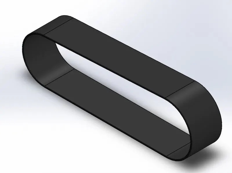
A transmission belt helps us to transmit the power generated by our engine to our wheels that are not axially aligned. These are simple, inexpensive, minimal lubrication, maintenance is low. The clutch is used by releasing the tension in the belt. Different speeds can be achieved by manipulating stepped or tapered pulley. - Kick Stand:
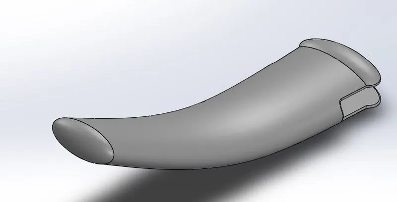
This part keeps the bike from tipping over when there is no person sitting on it. The kickstand helps the bike to achieve equilibrium by being in contact with the ground and bike. - Front Fender:
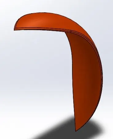
A fender typically is a cover for the tire since that comes in contact with the ground. The idea is to prevent any mud, rocks, liquids, slug gets thrown into the air when the rires are rotating. - Rear Fender:
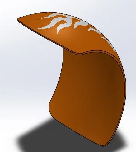
A fender typically is a cover for the tire since that comes in contact with the ground. The idea is to prevent any mud, rocks, liquids, slug gets thrown into the air when the tires are rotating. - Oil Tank:
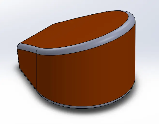
As the name suggests this is a contaciner for holing oil. The purspose of the oil tank varies as per our engine design. Most times the use is to ensure the engine has enough oil and there is smooth operation. There can also be coolants for the engine. - Chain:
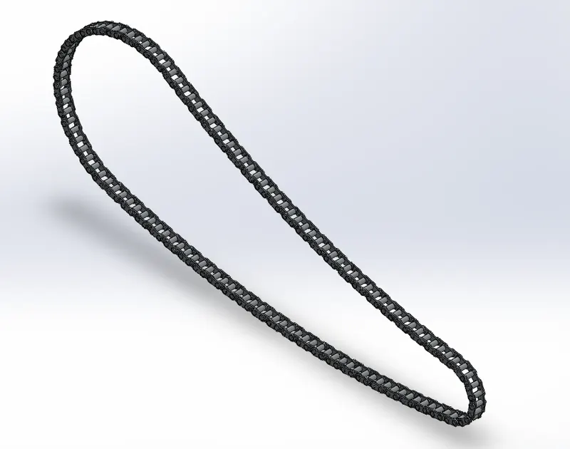
The idea of chain is to transmit the power generated by the engine to the Rear wheels. The one is question is a Roller chain used on bikes, this consists of outer plate, inner plate, pin, bushing and a roller. This complete set up can ensure efficiency of upto 98%.
- Pedal:
I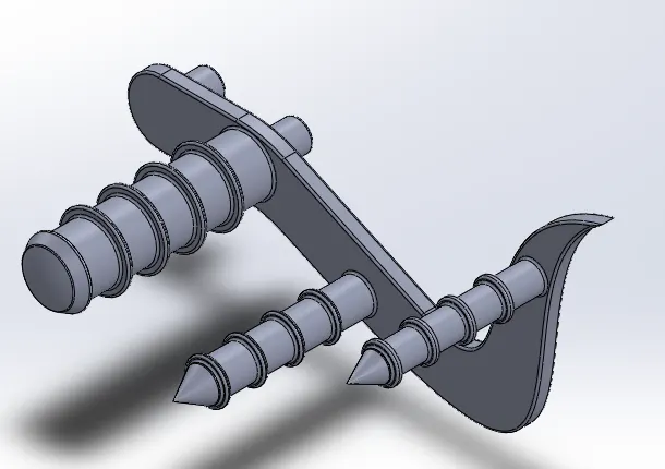
Pedal on our bikes serve multi purpose. Manuplating the position of the pedals help us to swirch gears to increase or decrease speeds during transmission. The other ides is also to provide a resting place for the rider. - Front Wheel:
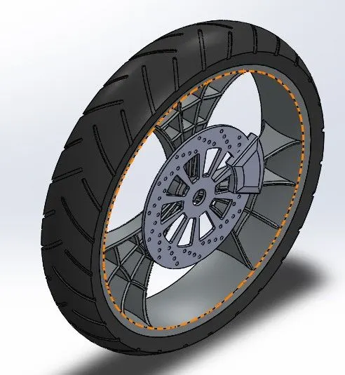
The Wheels have been in existence since the Neolithic age. They have served us for millions of years in transportation. In the case of bikes specially choppers the front wheel is always larger in diameter and slimmer when compared to its companion. These models help us ensure us the turning motion is smoothly achieved. If we take a close look at our image we can notice the disc brake gripped by a caliper is also mounted on the front wheel.
- Rear Wheel:
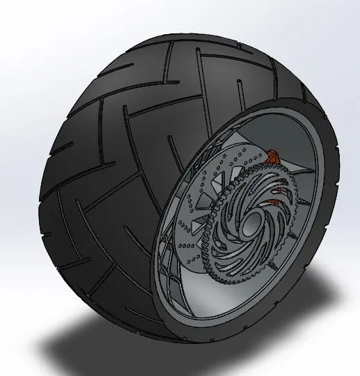
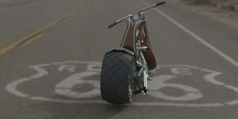
The Rear Wheel in the case of a chopper bike is Large and wide. The reason is to provide max traction between the road and the bike to avoid any splipage. If we take a close look at our image we can notice the disc brake gripped by a caliper is also mounted on the rear wheel. - Front Fork:
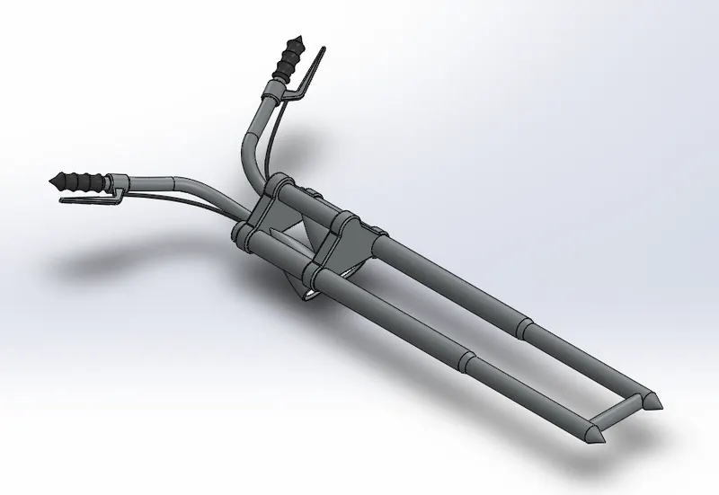
We have different types of forks for chopper bikes like Telescopic, inverted, springer and girder. In our case we have a Telescopic. Lower sleeve slides up into the upper sleeve within the tube there is a coil spring. The compression of spring provides a smooth ride. - Chassis:
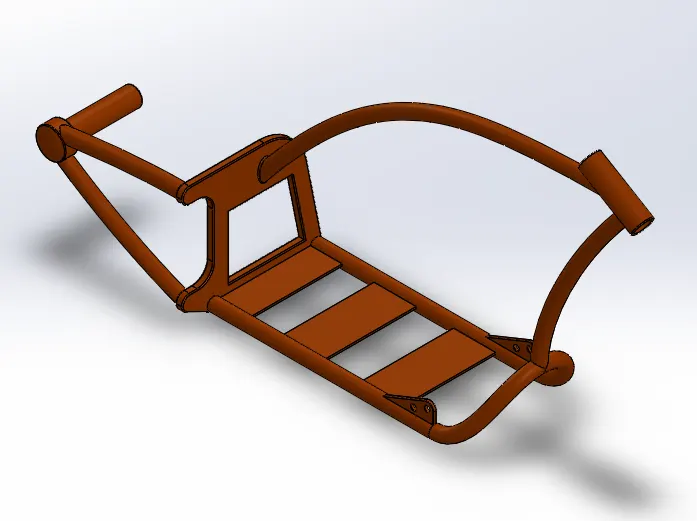
Frame of a bike or in this case a chopper is a crucial part of design element. This frame provides a base to build/ join the model together. Where to attach the rear wheel and front wheel, where to mount the engine. - Engine:
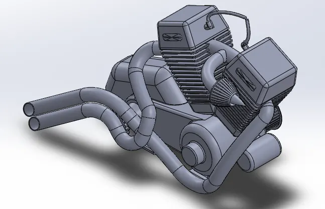
This is the heart of any bike is its engine. This decides how fast would a bike go and how well can it perform. In most chopper’s V-twins are used in iconic fashion as meant to. This where the fuel is mixed and compressed to generate the to and fro motion for the pistion in the case of diesel engine. In the case of petrol engines the compreseed fuel air mixture is ingnited with sprak plugs to provide to and from motion of the pistons. The Pistons in turn are coneected in a V orientation to ensure when one is compressing the other is expanding. This linear motion is converted over to the rotors which with the help of bevel/ sun gears/ spur gear depending on the design trasnmoit the power onto the chain and wheels. Thus achieveing motion. - Gas Tank:
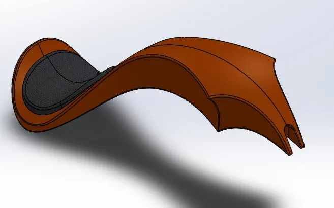
A container to store fuel is an essential part of any transportation. Here we have the opputunity to design the tank in a fashion that it provides the aesthetics and does the job of storage as well.
- Parts Assembly:
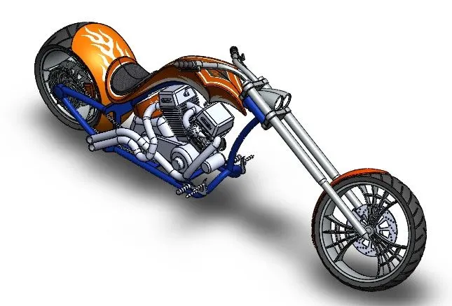
The Second step is to Assemble the parts with respect to each other. With the use of constrains while matting or bringing them together with the help of features like Coincidence, Concentric, Angle, Distance, Parallel, Width Defining, Tangency, Limit angle etc.
These constrains can be between two points of the model, two surfaces, two planes, two vertexes, two edges or this could be combination of a plane and surface, plane and edge etc. We can shuffle through any two options and constrain them together to assemble the model.
- Rendering Model:
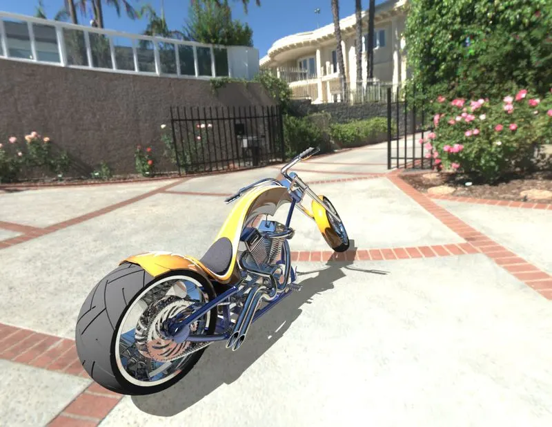
The Final step towards completion would be Rendering of the Chopper. In this section we would be applying aesthetics (Lights, Shadow, Environment, Back drop light and camera views) to mimic the real world with the help of PHOTOVIEW 360. - Appearance:
Here we can provide our model the appearance we desire by applying a material like glass, Metal, Paint, Rubber, Lights etc. This can be done by a simple drag and drop on the body or surface that we so wish to provide the material to. - Decals:
Here we can apply crafty symbols/ designs onto the surfaces that we want. We use mapping for defining the location and illumination for brightness of the craft. - Scenes:
Here we can add the environment in the back of our model. This utilizes the light in the environment as the light for our model. This could be in an Office room, Back yard, Factory, Living room, Beach, Mountains etc. We can define the amount of reflection from the environment onto the model and the brightness of the scenery. - Lights:
We have option while adding lights like Directional Light, Spot Light, Point Light and Sunlight.
We have used the Directional light we get the option to choose where longitudinally and latitudinally be located and then define the brightness created by them the light. We also have to define the shadow intensity and quality that it creates. - Camera:
In this option we can create a camera of specified lenses power by defining options like filed of view angle, Length, height, Depth of field etc. while aiming at the target/Model.
We can also position our camera for animation purpose on a specific body Ex: It would rotate around the model. - Options:
One of the most important features that decides the resolution of the picture that will be rendered and quality of it.
Here we can define the photons from the surface for reflection (Caustics) and level of brightness on the surface of those lights (Bloom).
CONCLUSION
- The parts of the chopper are modeled.
- The parts are inserted into the assembly environment and the chopper is assembled.
- The realistic image was rendered with the use of the Photoview 360 & Solidworks visualize.
In desiging ,from parts upto the assembling them from 2d to 3d the lessons were amazing it help in uderstanding almost all feature which are very necessary and makes thigs easy. Doing in reality it makes work easy and less time consuming. Thighs like rendering, photoview 360, etc were easy to use and can be learn easily. solidwork is makes thigs easy within time.