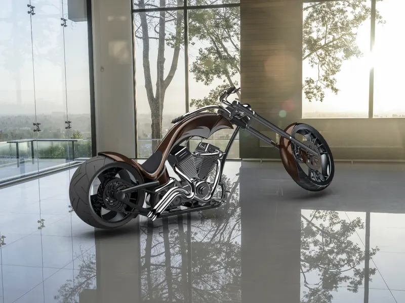
Photo Realistic Rendering
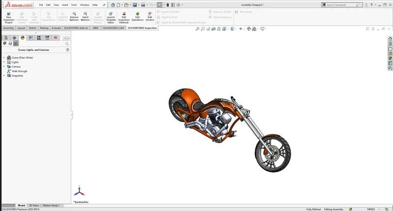
Report on Assembly of Chopper Model
Objective:
To understand the various features in solidworks which can be used in designing the various components of the Chopper model.
Introduction:
SolidWorks is an open software which can be used in the real world to understand how the things are made and also help us to enhance our knowledge by helping our imagination to become reality wich can be achieved through the help of solidworks software.through this software we can perform several useful task which can be applied in the real world.we can design various components and machines parts using it such as Chopper,yatch etc..when in helps us to visualize various components and parts used to make a model and also create environment and visualize it using the help of the software before applying in the modern world.
Design methodology:
- first most important thing is to have solidworks installed in the pc.
- once we open it we can see three option where we can select parts file
- then the workspace is will appper on the screen where we can start our sketch
- before that on the left bottom of the screen we can see various units we normally us MMGS so select it from the pop-up.
- then using various features prensent in the top menu bar which can be used to sketch what we need.
- once we complete sketching we need to save or else we will loose whatever we created
Description:
Sketch:
we have
smart dimension-which can be used to give measurement values to the given sketch.
then we have basic features like line,circle,rectangle,spline,3-point arc,ellipse,polygon etc...
next we have trim entities-which can be used to cut and unwanted part in the sketch using various trim option.
offset entities-it is used to give the same exact line inward or outward according to the spacing which we give.
Offset on surface -same as offset entities but only offset on the surface.
mirror entites-mirrors the same exact sketch which can be used in symmetric sketch so it reduce a lot of time.
linear sketch pattren-by selecting a line along with reference and giving the number of count it should pattern on the sketch so we no need to create each and every pattern and waste time.
move entites-it helps in moving of the created sketch entites.
sweep-creates a cut surface
Excrude boss-helps to create a section in the sketch using temporary line as the reference axis.
Lofted-it uses two sketch created on the surface
swept cut-we can select the bodies which we want to remove and keep the rest
fillet-it us used to smoothen the curved edges.
chamferes-same as fillet but can be used in tight and odd places.
split-used to cut parts from the bodies.
combine-used to compine two sketch.
Dome-used to create a curvy surface around the part where fillet cannot be used.
boundary cut-can be used in cutting profile in both direction by using sketch,face etc.. as reference.
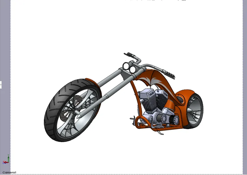
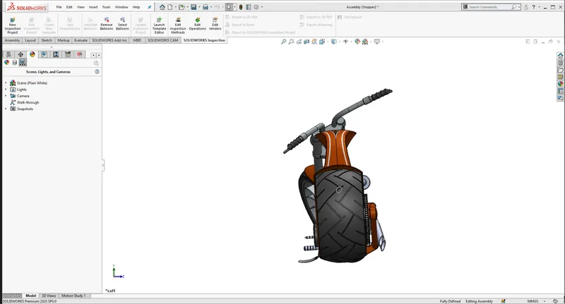
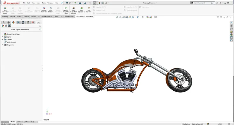
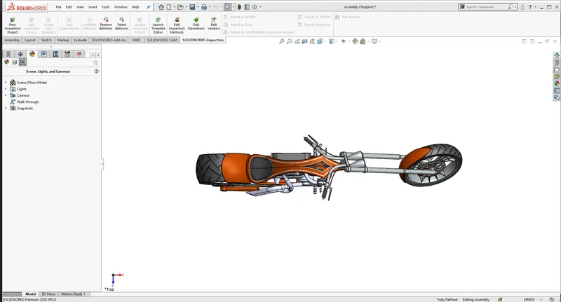
Rendering:
Conclusion:
from this we have learnt to create American Chopper with the help of Solidwork software.