Photo Realistic Rendering
Title of Project- Assembly of Chopper Model in solidworks
Objective- To Design and assemble the Child Parts of chopper and then rendering of Assembly
Introduction- Solidworks is a solid modelling computer aided design (CAD) and computer aided engineering (CAM), application published by DASSAULT SYSTEMS. Using this software, I designed and assembled the child parts of Chopper and finally rendered the assembly using SolidWorks Visualize software.
Design Methodology-
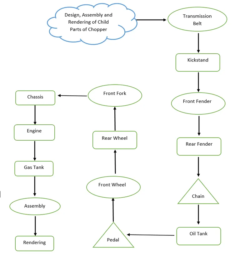
Description-
- Transmission Belt- I used line command, tangent feature to design the sketch and then extrude the sketch.
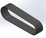
- Kickstand- To design this part I used Loft, Dome, Split and Fillet commands.
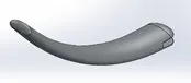
- Front Fender- To design this part I used Axis, Revolve, Split and Fillet commands.
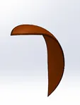
- Rear Fender- To design this part I used Revolve, Split, Fillet and Shell commands.

- Chain- To design this part I used Block, Extrude, Fillet and Circular Pattern commands.
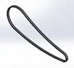
- Oil Tank- To design this part I used Extrude, Combine, Fillet and Shell commands.
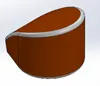
- Pedal-To design this part I used Extrude, Fillet, Revolve, Dome, Chamfer and Linear Pattern commands.
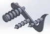
- Front Wheel-It has three different solid parts i.e. Rotor, Caliper & Tyre, to design this part I used Boss Extrude, Cut Extrude, Cut Revolve, Circular Pattern, Chamfer, fillet and Combine commands.

- Rear Wheel-It has three different solid parts i.e. Rotor, Caliper & Tyre, to design this part I used Boss Extrude, Cut Extrude, Cut Revolve, Circular Pattern, Chamfer, fillet and Combine commands.

- Front Fork-To design this part I used Boss Extrude, Cut Revolve, Linear Pattern, Revolve, Dome, Projected Curve, New Plane Insertion, Mirror, Combine commands.

- Chassis-To design this part I used Sketch Image, Projected curve, Sweep, Mirror, Dome, Split Revolve and Reference Plane commands.
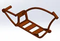
- Engine-To design this part I used Composite curve, Pierce, Boss Extrude, Cut Extrude, Sweep, Composite curve and split commands.
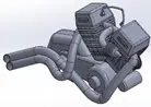
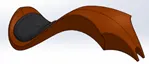
- Gas Tank- To design this part I used Sketch Image, Surface Sweep, Surface Trim, Surface Loft, Composite Curve, Mirror, Surface Knit, Boundary Surface and Cut Sweep commands.
- Assembly- To assemble all the child parts, I used different mates scuh as concentric, Tangent, Width, Parallel, Coincident and Advanced Mates.
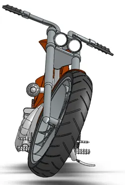
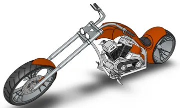
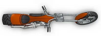
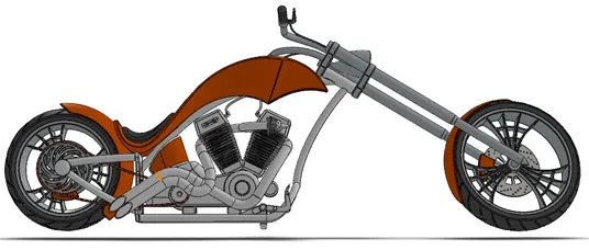
Rendering Image
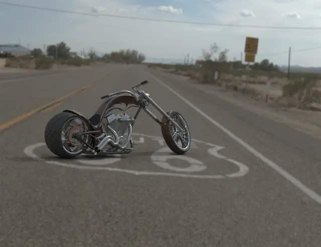
Conclusion- After completing this project from multiple child part designing to complete assembly and then rendering the Assembly to make model realistic, Now I have confidence to design parts in SolidWorks using different tools.