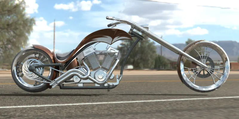
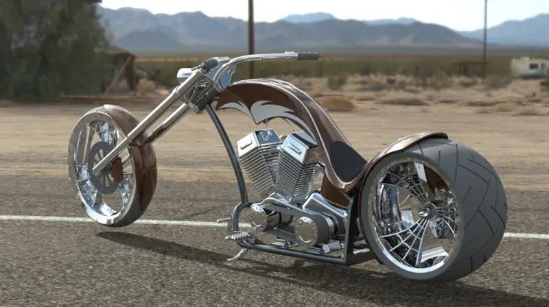
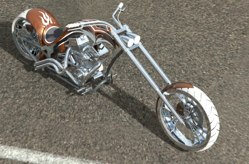
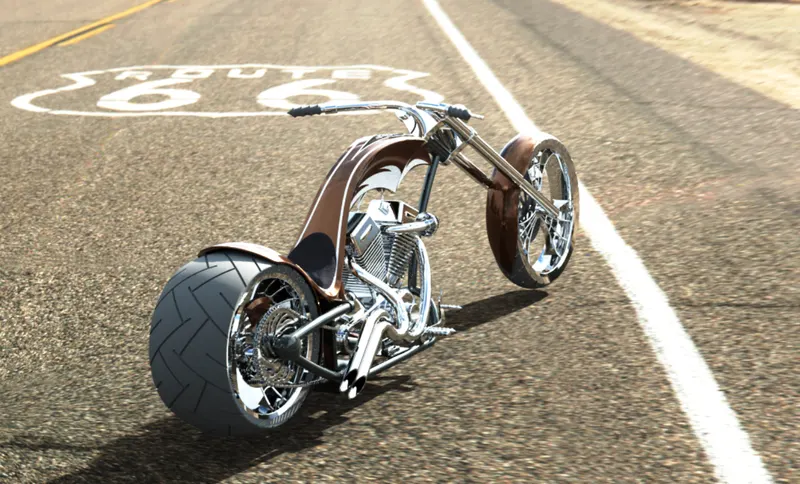
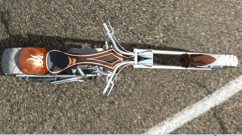
Photo Realistic Rendering
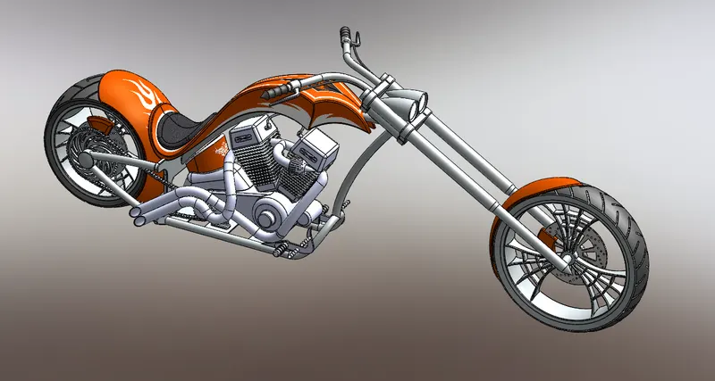
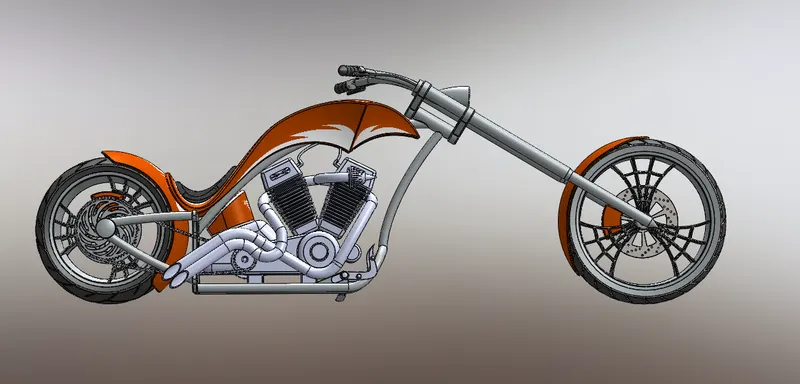
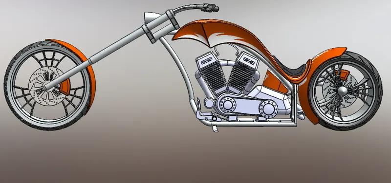
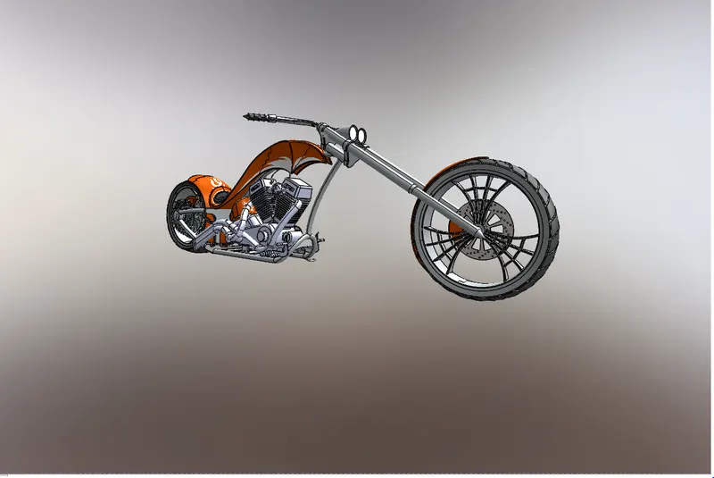
Title Of The Project: Design and modelling various parts of the americon chopper and assembly of americon chopper using CAD software using solid works 2019 including complete rendering of americon assembly chopper.
Objective: main purpose of this project is to modelling the assembly of american chopper and rendering the chopper using solidworks visualize 360 professional 2019
Introduction: choppers are bikes or featured on television of american chopper for a specific corporate or celebrity customer.
the function of the motor usually takes a back seat to the presentation of the theme, and this motor cycles attract attenstion solely on the premise of the theme itself
Design Methodology/Approach:
firstly, design the all individual components of american chopper.
namely:
1. transimission belt drive
2.kick stand
3.front fendor
4. Rear fendor
5.oil tank
6. Chain
7. foot pedal
8.front wheel
9.Rear wheel
10.Front Fork
11.Chassis
12.Engine
13.Gas Tank
explanation:
Transimission Belt: The main purpose of the transimission belt is transmit the power which is developed inside the Engine to Gear box with Maximum Efficiency
FLOW CHART:
1 sketch
2. boss extrude
3. fillet
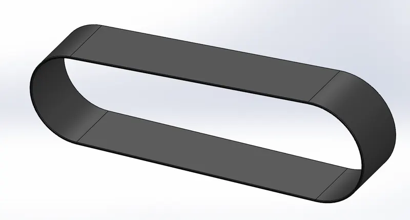
Procedure to create a transimssion belt:
1. firstly open the solid works software then select new part to create a model
2.change the name front plane to front plane LSW
3. select front plane LSW
4. Enter in to 2D sketch
5. Draw the Two circles with given diameter with some distance by using offset option
6. Exit From 2D sketch
7. select the boss extrude to extrude the 2D model for given distance
8.Apply the fillet tool to have proper design of Belt drive to change appearance of the Belt and finally save the model.
9. save the model
KICK STAND:
A side stand style kickstand is a single leg that simply flips out to one side, usually the left side, and the bike then leans against it. Side stands can be mounted to the Chain stays right behind the bottom bracket or to a chain and seat stay near the rear hub. Side stands mounted right behind the bottom bracket can be bolted on, either clamping the chain stays, or to the bracket between them, or welded into place as an integral part of the frame.
1.Sketch
2.Loft
3.Dome
4.Cut Extrude
5.Split
6. Boss Extrude
7. Fillet
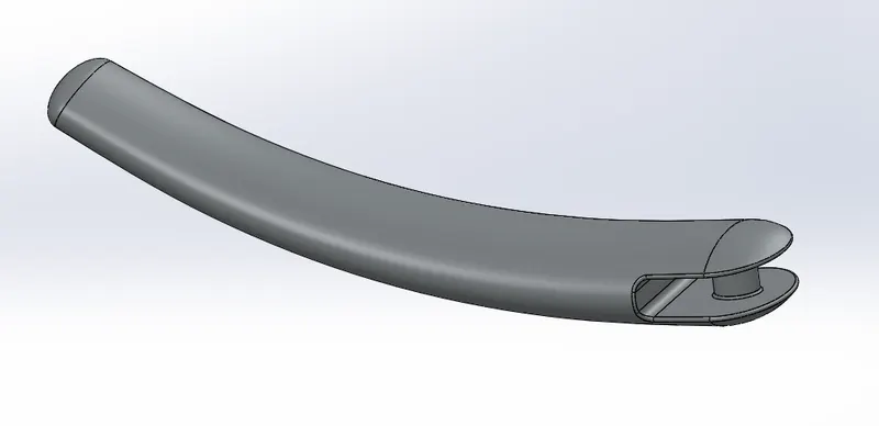
1.first open solid works then select new part to creat a new model
2. change the front plane in to front plane LSW
3.Then select right plane for sketching
4.Then draw the 2D sketch by sketch commands, spline,and trim commands and apply dimensions,relations for fully defind sketch.
5. Then creat a new planes and draw ellipse in news planes as per required
6. Then use loft commond to creat a loft to kick stand
7. Extrude Cut Command is used to cut unwanted in the kick stand and save the model
3. Front fendor:
Its primary purpose is to prevent sand, mud, rocks, liquids, and other road spray from being thrown into the air by the rotating tire. Fenders are typically rigid and can be damaged by contact with the road surface.
1.sketch
2.Offset entities
3.Trim Entities
4.Revolve
5.Dynamic Error
6.Split
7.Fillet
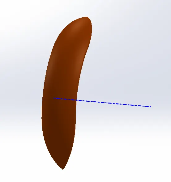
The following procedure is used to create a front fender:
1. initially open the solid works then select new part to create a new model
2.then change the default names of planes as
front plane in to vertical plane front fender
Top plane into center plane front fender
right plane in to mid plane front fendor
3. then select the vertical plane front fender for sketching
4 then draw the 2D sketch by using Sketch commands,Spline and trim commands and apply dimensions,realtions for fully defind sketch
4. Rear Fender:
Motorcycles have fenders in their wheels mainly because to provide fork support, dirt and mud protection, and manage air drag for a smooth ride.
features to create a rear fender
1.sketch
2. offset entities
3.Trim entities
4. revolve
5.split
6.fillet
7. shell
8. apperance
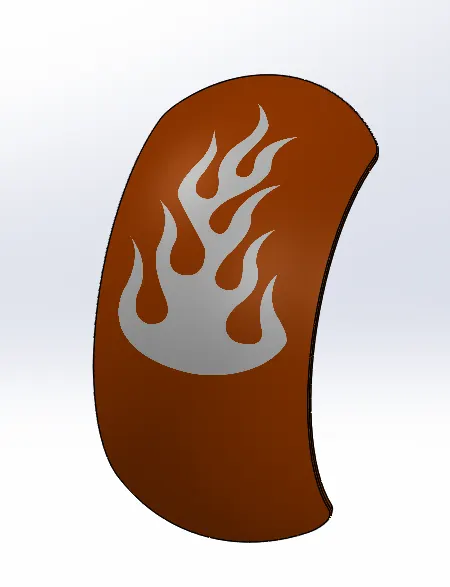
The following procedure is used to create a rear fender
1. First open solid works then select new part to create new model.
2. Then change the default name of planes as Front plane in to vertical plan Rear fender, Top plane in to centre plan Rear fender, Right plane in to Mid-plane Rear fender.
3. Then select centre plane Rear fender for sketching.
4. Then draw the 2D sketch by using sketch commands, spline and trim commands and apply dimensions, relations for fully defined the sketch.
5. Then change the appearance of rear fender and save the model.
5.Oil Tank:
The oil tank is hallow section, and main purpose of oil tank is used to store the oil and supply the oil to engine while run the vehicle.
Features used to create a Oil tank:
1. Sketch
2. Boss extrude
3. Combine
4. Shell
5. Fillet
6. Appearance
The folloing procedure is used to design a oil tank:
1. First open solid words then select new part to create new model.
2. Change front plane into mid plane oil tank and select top plane for sketching in 2D.
3. Then draw 2D sketches by using sketching commands then add dimensions and relations as required for fully defined sketch then combine the model.
4. Then do shell and fillet commands and change the apparance and save the model
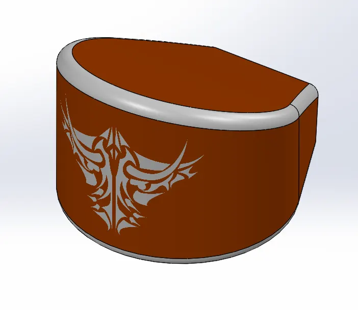
CHAIN:
The drive chain of a motorcycle is a very important element of the motorcycle drivetrain. Some bikes also use shafts and belts for the final drive but most motorcycles rely on chain and sprocket setup for the job. The final drive is responsible for transferring the engine power to the rear wheel.
Feature used to create a chain:
1. Sketch
2. Boss extrude
3. Fillet
4. Curve driven pattern
5. Mirror
The following procedure is used to design a chain:
1. Initially open solid words then select new part to create new model.
2. Then change the default names of planes as Front plane in Midplane chain, Top plane in to centre plane chain, Right plane in to front plane chain.
3. Then draw 2D sketches by using the sketch commands, and give dimensions and relations as we required for fully defined the sketch.
4. Then use curve driven pattern and fillet the chain.
5. Then change the appearance of chain and save the model.
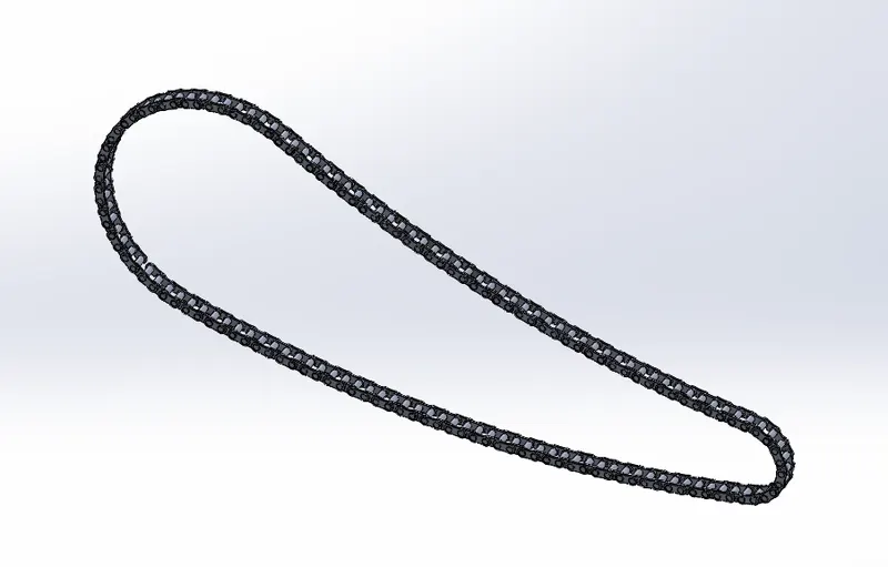
FOOT PEDAL:
The pedal is the part of a bicycle that the rider pushes with their foot to propel the vehicle. It provides the connection between the cyclist's foot or shoe and the crank allowing the leg to turn the bottom bracket spindle and propel the bicycle's wheels.
Features used to create a chain:
1. Sketch
2. Boss extrude
3. Revolve
4. Dome
5. Fillet
6. chamfer
7. linear pattern curve
8. appearance
The following procedure is used to create new pedal:
1. Initially open solid words then select new part to create new model.
2. Then select Front plane for 2D sketch.
3. Then draw 2D sketches by using the sketch commands, and give dimensions and relations as we required for fully defined the sketch.
4. Then apply dome, fillet and chamfer commands to sketch.
5. Then add linear pattern curve for sketch and chande the appearance of sketch.
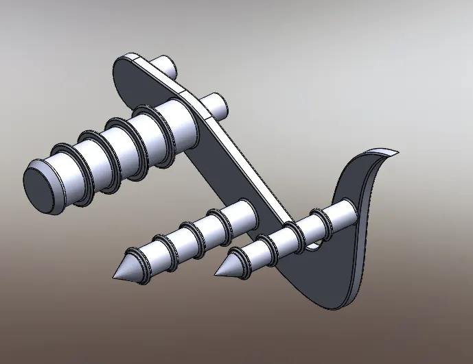
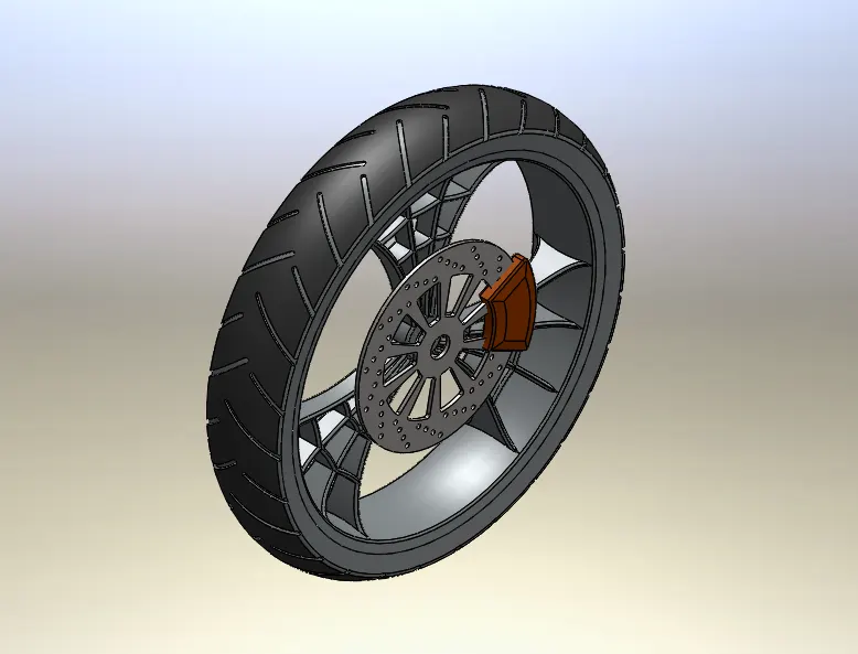
FRONT WHEEL:
Motorcycle wheels are made to cope with radial and axial forces. They also provide a way of mounting other critical components such as the brakes, final drive and suspension. Wheels, and anything directly connected to them, are considered to be unsprung mass Traditionally motorcycles used wire-spoked wheels with inner tubes and pneumatic tyres. Although cast wheels were first used on a motorcycle in 1927, it would not be until the 1970s that mainstream manufacturers would start to introduce cast wheels on their roadgoing motorcycles. Spoked wheels are usually made using steel spokes with steel or aluminium rims. Cast wheels are predominantly made from an aluminium-alloy, but can also be made from more-exotic materials, such as magnesium content alloy or carbon fibre.
Features used to create a Front wheel
1.Sketch
2.Revolve
3. Boss Extrude
4. cut extrude
5.Circular pattern
6. linear pattern
7.combine
8.Trim
9.Fillet
10.Chamfer
the following procedure is used to design a front wheel
1. open the soild works then select new part tio creat new model
2. then select front plane for 2D sketch
3.then draw all 2D sketches by sketch commands and add dimensions and relations as required for fully defined sketch
4.Then apply linear Pattern,circular pattern,fillet,chamfer and combine commands to design.
REAR WHEEL:
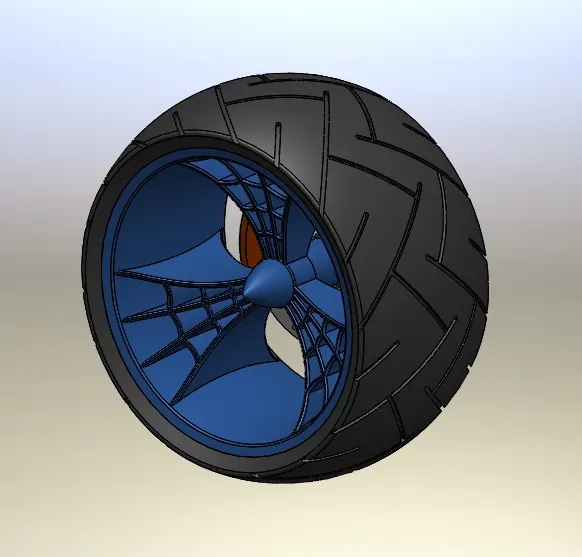
During heavy acceleration when the weight of the vehicle is transferred to the rear axle, rear wheel drive vehicles provide better traction in contrast to FWD vehicles. Use of front mounted engine with RWD helps to achieve the better weight distribution of the vehicle.
features used to create a Rear wheel:
1. sketch
2.revolve
3.cut extrude
4.boss extrude
5.circular pattern
6.combine
7.revolve cut
8.fillet
9.chamfer
10.Apperance
the following procedure is used to design a rear wheel:
1.To start with initially open the soild works then select new part tio creat new model
2. then select front plane for 2D sketch
3.then draw all 2D sketches by sketch commands and add dimensions and relations as required for fully defined sketch
4.Then apply linear Pattern,circular pattern,fillet,chamfer and combine commands to design.
5. then change the apperance of real wheel
FRONT FORK:
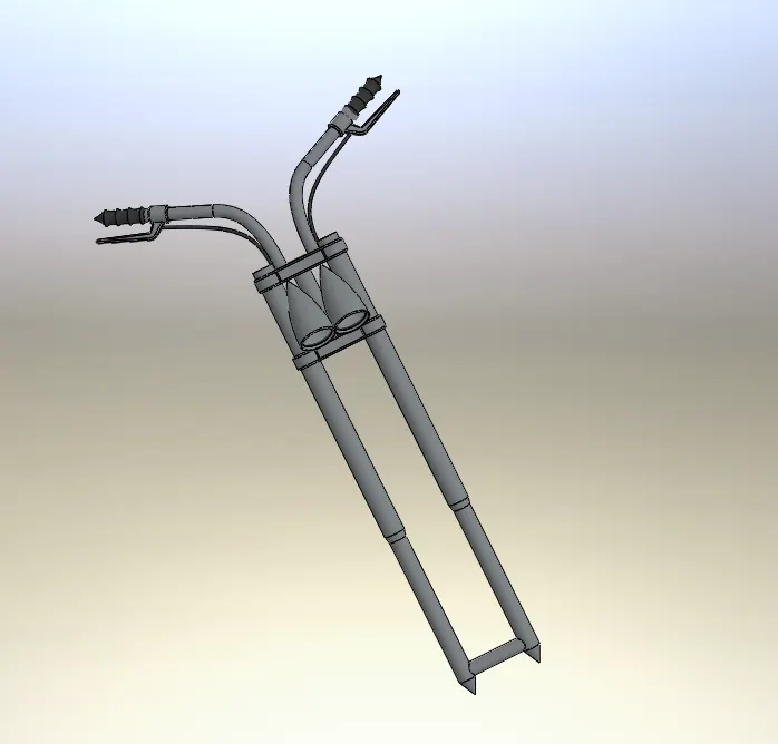
A fork typically consists of two blades which are joined at the top by a fork crown. The crown is often at the front. Most suspension forks have an arch connecting the two side of the lowers (the part connected to the axle.) It is often in front of the stanchions (shaft the lowers slide on) but not always. Above the crown, a steerer tube attaches the fork to the bicycle and the handlebars (via a stem) allowing the rider to steer the bicycle. The steerer tube of the fork interfaces with theframe via bearings called a headset mounted in the head tube.
features used to create a front fork:
1. sketch
2.revolve
3. boss extrude
4.Fillet
5.linear pattern
6.cut extrude
7.Dome
8.Revolve cut
9.Project Curve
10. Mirror
11.Combine
12.sweep
13. split
The following Procedure is used to make the front fork
1.To start with initially open the soild works then select new part tio creat new model
2. then select front plane for 2D sketch
3.then draw all 2D sketches by sketch commands and add dimensions and relations as required for fully defined sketch
4.Then mirror the object after that combine the object and use sweep command to get front fork finally spilt the object using split command.
Chassis:
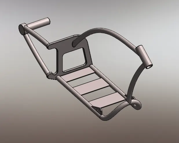
A motorcycle's chassis or frame forms its skeleton. All the components of a motorcycle, like the suspension, wheels, fuel tank, seats, handlebars etc, are attached to this base structure which lends a motorcycle its strength and ability to handle well.
features used vto creat a chassis
1. sketch
2.project curve
3.boss extrude
4.offset
5.Trim
6.Sweep
7.Split
8.Revolve
9.Cut EXtrude
10.FIllet
11.Combine
12.Mirror
13.chamfer
14.Dome
15. bottom plane fuel tank
the following procedure is used to develop a chassis
1.open the solid work then select new plane to creat a new model
2. then change the default names of planes as
front plane in to mid plane chassis
2.Top plane in to bottom plane chassis
3.then select mid plane chassis for sketch then get the sketch picture in the mid plane chassis and then change the x and y directions positions and transparency as per required
4.Then exit the sketch and the sketch as chassis
5. Then Draw the 2D sketches by using planes and sketches commands and give dimensions and relations as per required to fully defind sketch
6. save the chassis by changing apperance if we want
Engine:
A heat engine is a machine, which converts heat energy into mechanical energy. The
combustion of fuel such as coal, petrol, diesel generates heat. This heat is supplied to a
working substance at high temperature. By the expansion of this substance in suitable
machines, heat energy is converted into useful work. Heat engines can be further divided into
two types:
(i) External combustion and
(ii) Internal combustion.
In a steam engine the combustion of fuel takes place outside the engine and the steam
thus formed is used to run the engine. Thus, it is known as external combustion engine. In the
case of internal combustion engine, the combustion of fuel takes place inside the engine
cylinder itself.
The IC engine can be further classified as: (i) stationary or mobile, (ii) horizontal or vertical and (iii) low, medium or high speed. The two distinct types of IC engines used for either
mobile or stationary operations are: (i) diesel and (ii) carburettor.
features used to create a engine:
1.sketch
2.Boss extrude
3.Revolve
4.Fillet
5.circular pattren
6.Dome
7.Cut Extrude
8.Chamfer
9.Linear pattern
10.Mirror
11.sweep
12.Project curve
13.split
the following procedure is used to create a engine:
1.open the solid work then select new plane to creat a new model
2.then select front plane engine for sketch then get the sketch picture in the mid plane chassis and then change the x and y directions positions and transparency as per required
3.Then exit the sketch and the sketch as engine
4. Then Draw the 2D sketches by using planes and sketches commands and give dimensions and relations as per required to fully defind sketch
5.The change the apperance of engine and save the model
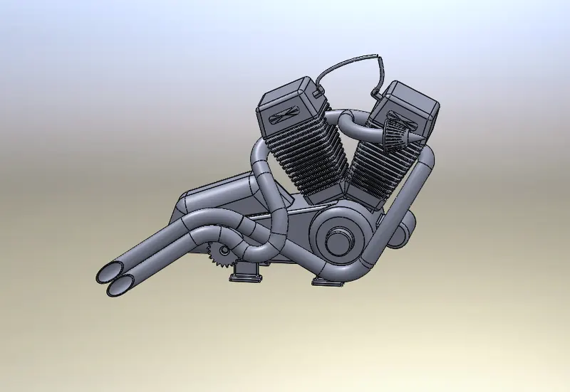
GAS TANK: the main function of the gas tank is to supply the gas to the engine whenever engine is needed
features used to creat a gas tank
1.open the solid work then select new plane to creat a new model
2. then change the default names of planes as
front plane in to mid plane fuel tank
2.Top plane in to bottom plane fuel tank
right plane in to front plane fuel tank
3.then select mid plane fuel tank for sketch then get the sketch picture in the mid plane fuel tank and then change the x and y directions positions and transparency as per required
4.Then exit the sketch and the sketch as Engine
5. Then Draw the 2D sketches by using planes and sketches commands and give dimensions and relations as per required to fully defind sketch
6. save the Gas tank by changing apperance if we want
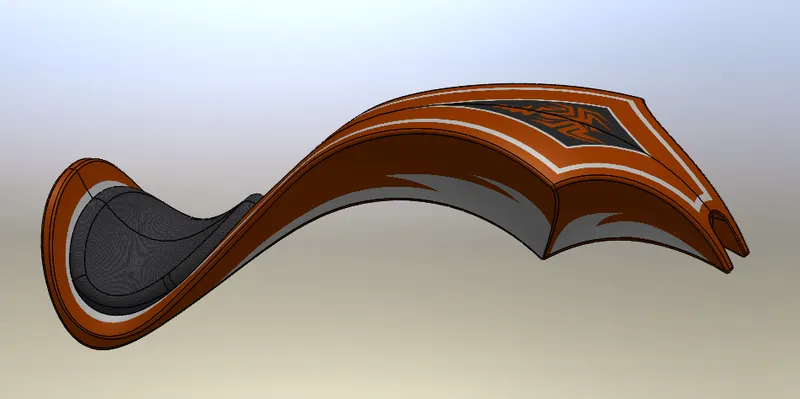
ASSEMBLY OF AMERICAN CHOPPER:
The main motive of assembly of american chopper is that assembly the all individual parts with suitable mates amd planes
The following procedure is used to create an assembly ofg american chopper
1 click on file then open all the components and then open the assembly file
2.then open insert components and then select chassis and insert then ok
3.then insert engine manually in rough position then select front plane of engine and front plane of assembly and make coincident each other
4.Then select bottom face of motor and one of plane of frame and make coincident each other and then give distance between front face of plane and frame then replace front plane of assembly to mid plane chassis then mate save
5.then expand part and rebuild dimensions as per orientation and do collpse items
6.Then insert pedal manually inside of assembly to position and then select outside pedal and inside of frame plane and make concentric and coincident again open the engine part and then modify as per orientation and then open assembly file and save
7.then mirror the pedal by using mirror component as per orintation and save
8.then insert the kick stand to nearest point of orintation and then mate the plane and kick stand then make parallel between midplane of kick stand plane of frame and give the angle as per required and save
9.then insert transmission belt and drag in to the closet position and select belt and pullys and make concentric to each other and then select two out sides face of pully and then go to advance mate then select two faces of belt and pully and then modify the belt dimensions as per orientation and the collapse items and save
10.then insert oil tank and select bottom face of oil tank and top face of motor and make coincident and then select midplane of oil tank and mid plane of chassis and make coincident and save
11then insert oil tank and select bottom face pf oil tank and top face of motor and make coincident and then select midplane of oil tank and midplane of chassis and make coincident and then save
12.then select right plane of rear wheel and midplane of chassis and make coincident and then select right plane of chassisand front plane of rear wheel and make parallel and then collapse items and save
13.then insert rear fender in correct orientation by changing Y andZ directions and then select the one side of fender and tire face and make concentric and then select midplane rear fender and mid plane of chassis and make coincident and again select plane of rear fender and right plane of chassis and make parallel and save
14.Then insert chain to nearest place and then select midplane of chain and mid plane of chassis and make parallel to each other. then mate the chain and sprocket with each other and then collapse items and save
15.Then insert gas tank in the closest place and then select front plane of fuel tank and plane 2 of chassis and then make coincident each other and then select bottom plane of fuel tank and bottom plane of chassis and then make coincident and then midplane of fuel tank and miplane of chassis make coincident and modify the one of coincident mate as petr orientation and save
16.Then insert front fork to front face of model and then select stem of fork and front part chassis and make concentric each other
17.then mate the upper and lower arms and top and bottom of section and control the angle by using mate command between front plane of fork and mid plane of chassis and select midplane of chassis and front plane of fork make patrallel and collapse items and save
18.then inmsert front wheel ny rotating Y direction and make concentric with between wheel and axle
19.then create a plane by using roll back feature tree and mid plane of fork and right plane ofwhell and vertical plane of front fork and make coincident each other and save
20.Then insert front fender by using changing direction of Y direction as per orintation
21.then select vertical plane front fender and vertical plane fork and make coincident and midplane of fender andthen select centre plane of front fender and top plane of wheel and make coinident and midplane of fender and right plane of wheel make coincident and collapse items and save
22.Then edit chassis and chain as per orintation and save the file
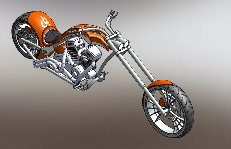
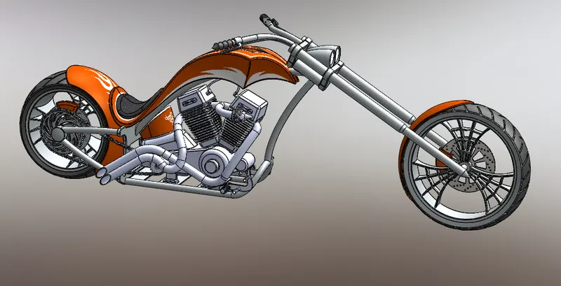
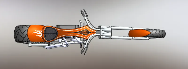
RENDERING IMAGES
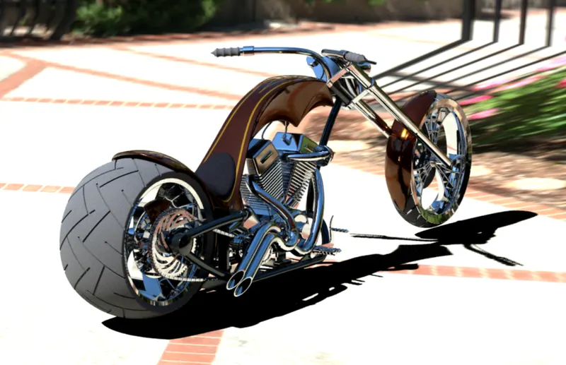
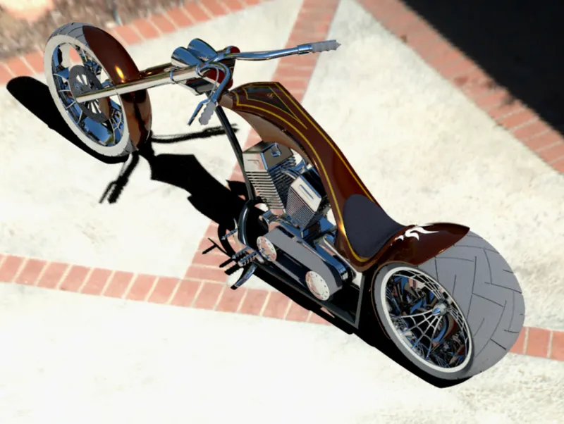
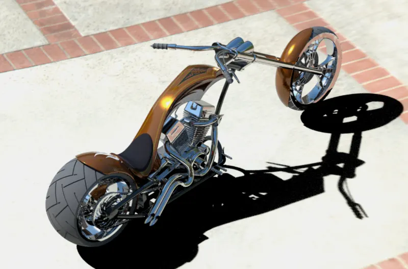
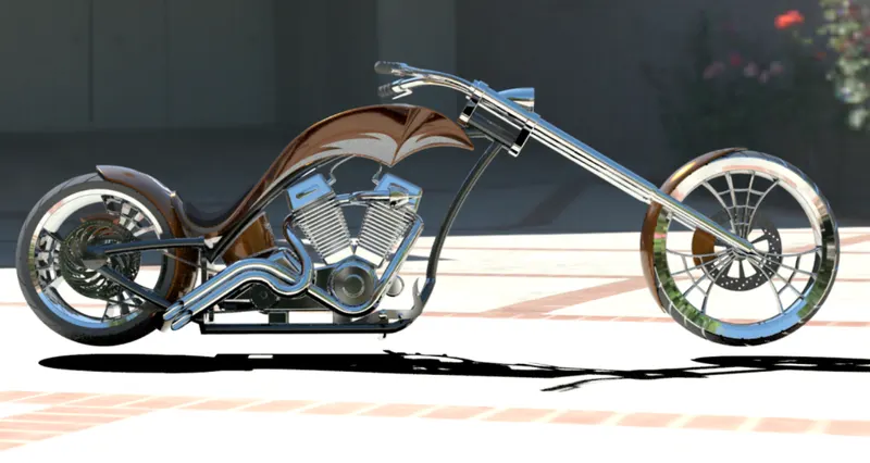
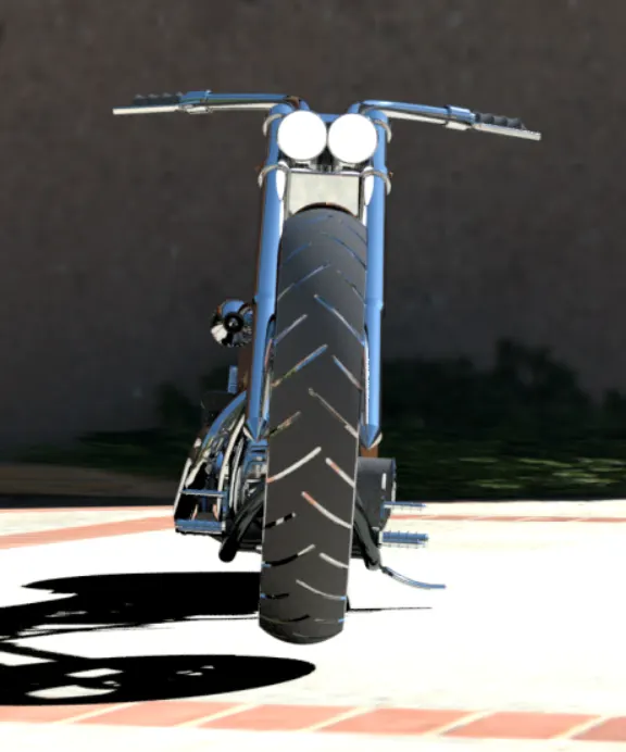
ROUTE 66 render pics