Photo Realistic Rendering
DESIGN OF AMERICAN CHOPPER USING SOLIDWORKS
INTRODUCTION
This report contains a detailed explanation of designing an American chopper using solidworks from part modelling to final rendering of the assembly using Solidworks software. Solidworks is mechanical 3D CAD software used to create 2D &3D models, which helps us in conceptualizing, understanding of ideas and prototyping faster and cheaper than ever.
OBJECTIVE
To learn the solidworks interface and simulation sketch or model the parts of american chopper, apply appearance and materials,
- Design the model of differnt components
- Assemble all parts of the chopper in the assembly
- Finally render the American chopper.
Parts modeled for designing the American Chopper
The follwoinf parts of the ameriacn Chopper are modeled and assembled in solidworks.
- Transmission
- Kickstand
- Front fender
- Rear Fender
- Chain
- Oil Tank
- Pedal
- Front Wheel
- Rear Wheel
- Front Frok
- Chassis
- Engine
- Gas Tank
FEATURES DESCRIPTION
- SKETCH
Sketch is a two dimentional representation of the model with respect to the plane/ veiw from the outside of the model. There are different types of sketching tools which maked the sketching a easy one. they are refffered to as line, arc, spline, cricle, rectangle, straight slot, polygon, elipse.
- OFFSET
Offset entities takes a copy of your existing geometry and copies it at an offset. Instead of recreating geometry.
- EXTUDE BOSS/ BASS
Is is feature which helps us in converting the 2D sketck to 3D solid model.
- EXTRUDE CUT
Is a feature opposite to boss/ bass, here we sketch on the surafce of the solid body and use this command in order to remove material.
- LOFT BOSS/ BASS
The loft feature creates a shape by making transitions between multiple profiles and guide curves. This tool is very valuable for modeling complex surfaces.
- FILLET
Fillet creates a rounded internal or external face on the part. You can fillet all edges of a face, selected sets of faces, selected edges, or edge loops.
- CHAMFER
The chamfer tool creates a beveled feature on selected edges, faces, or a vertex.
- SPLIT
The split tool is used to project an object onto other surface or curved / planar faces (sketches, solid, surfaces, faces, planes or surface spline) also capable to splitting faces into different bodies.
- DOME
Solidworks provides a tool called ad 'Dome' that you can create domes on 3D parts or shapes.
- REVOLVE
Create a sketch containing one or more profiles and a centreline, line, or edge that can be used an axis around which the feature revolves
- DYNAMIC MIRRORS
This is a very convenient tool where we can mirror the geometry/ sketch where we do not have to sketch again in the opposite side.
- TRIM ENTITIES
Based on the entities you choose to trim or expand the sketch can be trimmed or extended to meet the requirements.
- SHELL
For determining the thickness of thin and thick shell components, the shell definition property is used.
- LINEAR PATTERN
To create different no of instances needed to create the pattern linearly, the linear pattern bodies/ features are used.
- CIRCULAR PATTERN
To generate a different number of instances needed to create the pattern circularly, the circular pattern is used.
- SURFACE MODELLING
Surface modelling allows you the opportunity to produce a visual deception of the exterior of an object and its contours.
- APPERANCES
Appearances including colours and textures, determines the visual properties of a model. Physical properties, which are determined by materials, are not by appearances.
DESCRIPTION OF THE PARTS AND FEATURES USED:
- TRANSMISIONN BELT
Transmission belt is used to transfer power from input shaft to the gear box. Polyster material with the layers of Kevlar and sandwhiched with metallic wires is usually made. It is made of different components that gives it strength to transfer the full horse power produced from the motor to the gear box.
Features used:
- Sketch
- Extrude boss
- Fillet
- Offset
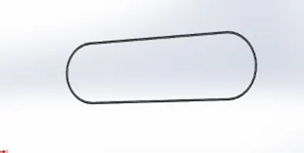
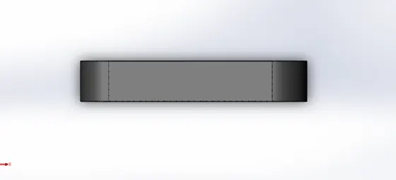
The transmission belt profile is produced according to the front plane, with a thickness of 3.5mm provided to the belt, the belt is extruded after the sketch has been finished. The square edges are smoothened using the fillet feature.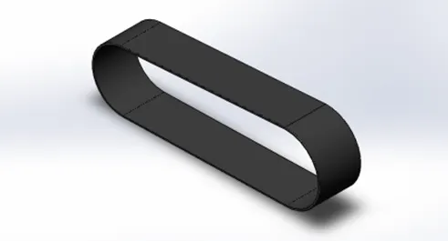
2. KICKSTAND
Kick stand is a supportive frame work provided to a bicycle or motorcycle to help it stand while stationary in a vertical position.
Features used:
- Sketch
- Loft
- Spline
- Dome
- Extrude boss
- Split
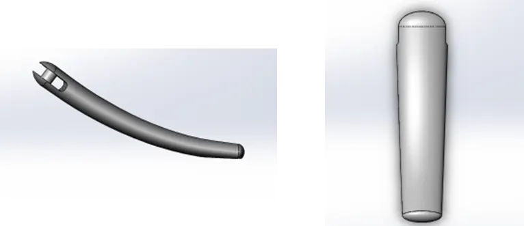
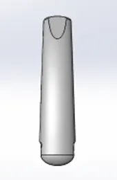
To build the kickstand loft feature is used, two ellipse sketch are produced on two different plane and guide line is drawn using the spline option so the loft created follows the guide and gives required shape. To bring the rounded ends on the kickstand dome feature is used considering the elliptical shape of the ends, the dome feature give a round end tangent to the loft surface. To the top a slot with an extrude boss for connecting it to the chassis. Split tool is used to cut the lower portion the loft feature to give flatness to region touching the ground
3. FRONT FENDER
The portion of automobile, motorcycle or a vehicle body that frames a wheel. Front fend for front wheel
Features used:
- Sketch
- Offset entities
- Trim entities
- Revolve
- Split
- Appearance
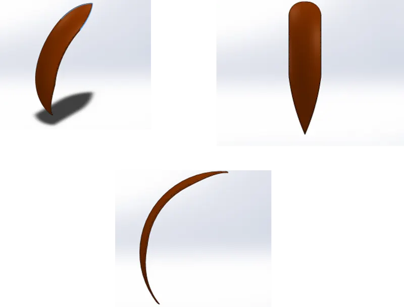
A sketch is made using a three-point arc in the front plane and offset to give the same thickness to overall the length of the part. By establishing an axis revolve feature is used to form the fender. Then on the top plane and the right plane two sketches are drawn to where it is used to split the revolved part to achieving the unique design of the chopper. The sharp edges are then taken care by using fillet feature and appropriate appearance is given as per requirement.
4. REAR FENDER
The portion of automobile, motorcycle or a vehicle body that frames a wheel. Front fend for rear wheel.
Features used:
- Sketch
- Offset entities
- Trim entities
- Revolve
- Split
- Appearance
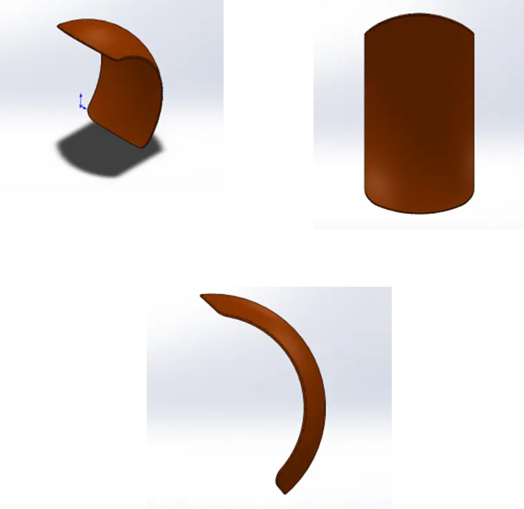
A sketch is made using a three-point arc in the front plane and offset to give the same thickness to overall the length of the part. By establishing an axis revolve feature is used to form the fender. Then on the top plane and the right plane two sketches are drawn to where it is used to split the revolved part to achieving the unique design of the chopper. The sharp edges are then taken care by using fillet feature and appropriate appearance is given as per requirement.
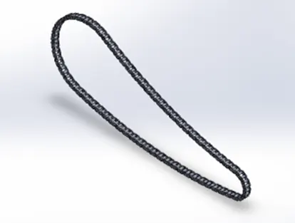
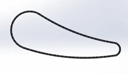
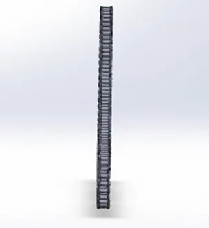
- CHAIN
Chain is the connection used to transmit power from the engine to the rear wheel. It passes over toothed member called sprocket.
Features used:
- Sketch
- Trim
- Fillet
- Blocks
- Extrude
- Mirror
- Patterns
- Appearance
Sketching two chain links and saving it as blocks and pattering the blocks along the guide path, pattering is not done in one stretch but in 4 segments so as to match the links properly accordingly, mirror feature is used to complete the link structure.
5. PEDAL
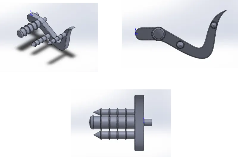
The external part mounted to the pedal. To rest the leg in riding position, the foot rest position deals major on the rider’s comfort on the bike.
Features used
- Sketch
- Extrude
- Fillet
- Linear pattern
- Dome
- Chamfer
- Appearance
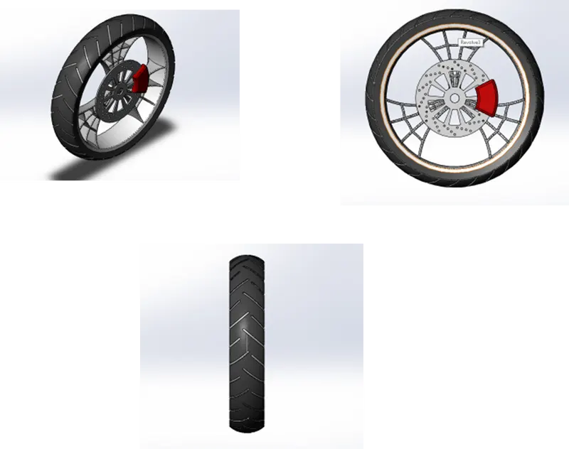
6. FRONT WHEEL
Wheels have a major function in smooth transmission of power and control, which consists of tire which is made if rubber which giver high friction contact on the road so that the power transmission is effective and which even affects the braking of the system.
Features used:
- Revolve boss
- Revolve cut
- Extrude boss
- Extrude cut
- Circular pattern
- Fillet
- Chamfer
- Combine
The rim of the wheel is revolved boss, spokes design is brought by using extrude cut, revolved cut, circular pattern, after the rim structure is formed, the tyre if the wheel is formed by using the revolved boss and to bring gripping pattern, the pattern is sketched and extrude and circular patterned, then the braking disc and the callipers are made.
6. OIL TANK
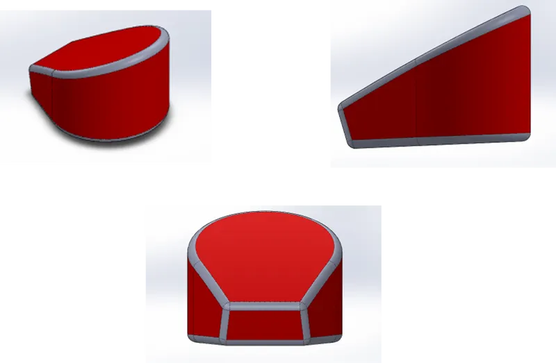
Oil tank is the reservoir of lubricating oil needed for the powertrain to work smoothly, efficiently, without wearing, over heating of powertrain components.
Features used:
- Sketch
- Boss extrude
- Fillet
- Shell
- Appearance
7. REAR WHEEL
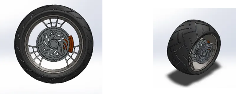
Wheels have a major function in smooth transmission of power and control, which consists of tire which is made if rubber which giver high friction contact on the road so that the power transmission is effective and which even affects the braking of the system.
Features used:
- Revolve boss
- Revolve cut
- Extrude boss
- Extrude cut
- Circular pattern
- Fillet
- Chamfer
- Combine
The rim of the wheel is revolved boss, spokes design is brought by using extrude cut, revolved cut, circular pattern, after the rim structure is formed, the tyre if the wheel is formed by using the revolved boss and to bring gripping pattern, the pattern is sketched and extrude and circular patterned, then the braking disc and the callipers are made, adjacent to the braking system the power train sprocket is also mounted.
8. FRONT FORK
Front fork is responsible for directing the chopper, which contains includes controls of throttle, clutch, braking, suspension, illuminating the path (head lights), instrument cluster detailing the information needed for the rider to ride safe and comfortable.
Features used:
- Extrude boss
- Revolved boss
- Fillet
- Dome
- Revolved cut
- Swept boss
- Projected curve
- Mirror
- Combine
- Chamfer
Projected curve is a feature to produce a 3D curve out of 2 different 2D curve
The methodology used is half of the fork if built then mirror, the handle bar and the cables are produced using splines and using swept boss. After mirroring the two halves are combined using the feature combine.
9. FRONT FORK
Front fork is responsible for directing the chopper, which contains includes controls of throttle, clutch, braking, suspension, illuminating the path (head lights), instrument cluster detailing the information needed for the rider to ride safe and comfortable.
Features used:
- Extrude boss
- Revolved boss
- Fillet
- Dome
- Revolved cut
- Swept boss
- Projected curve
- Mirror
- Combine
- Chamfer
Projected curve is a feature to produce a 3D curve out of 2 different 2D curve
The methodology used is half of the fork if built then mirror, the handle bar and the cables are produced using splines and using swept boss. After mirroring the two halves are combined using the feature combine.
10. FRONT FORK
Front fork is responsible for directing the chopper, which contains includes controls of throttle, clutch, braking, suspension, illuminating the path (head lights), instrument cluster detailing the information needed for the rider to ride safe and comfortable.
Features used:
- Extrude boss
- Revolved boss
- Fillet
- Dome
- Revolved cut
- Swept boss
- Projected curve
- Mirror
- Combine
- Chamfer
Projected curve is a feature to produce a 3D curve out of 2 different 2D curve
The methodology used is half of the fork if built then mirror, the handle bar and the cables are produced using splines and using swept boss. After mirroring the two halves are combined using the feature combine.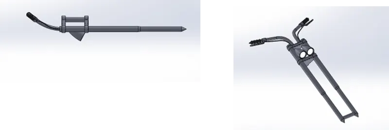
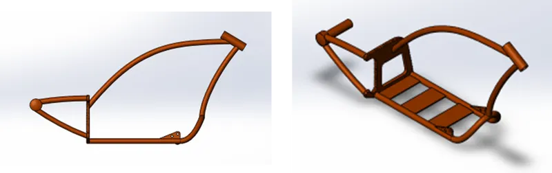
10. CHASSIS
It is the skeleton of the whole vehicle, which carries the heavy powertrain the strength and the aligning of the components on the chassis is responsible for perfect riding balance and stability.
Feature used:
- Sketch
- Offset
- Project curve
- Reference planes
- Sweep
- Split
- Extrude
- Spline
11. ENGINE
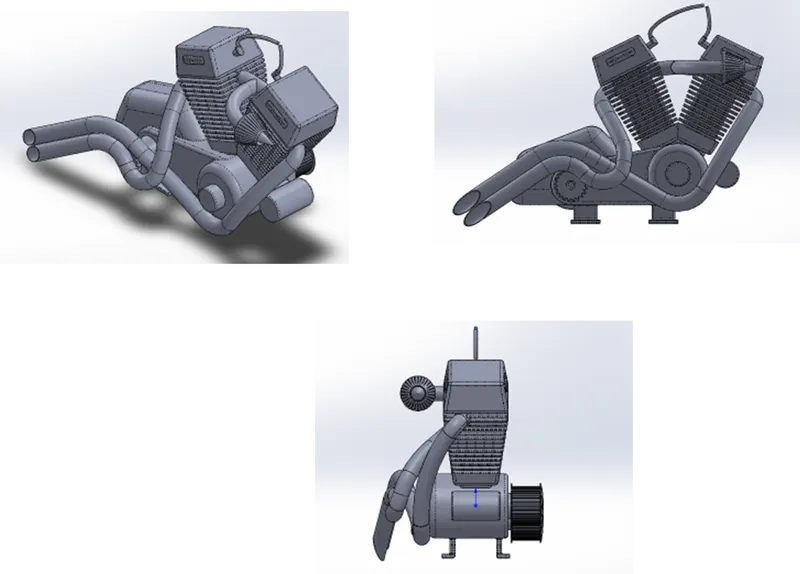
Engine or motor is a system that is designed to transform mechanical energy into one type of energy. Heat engines burn gasolines which is internal combustion engine where that heat is converted into useful mechanical energy.
Feature used:
- Sketch
- Spline
- Projected curve
- Composite curve
- Sweep
- Mirror
- Chamfer
- Extrude boss
- Extrude cut
- Revolve
- Circular pattern
- Linear pattern
- Fillet
- Dome
The engine modelling makes use of many features in the solidworks gives good idea on using projected curve, composite curves which is used to construct the silencers.
12. GAS TANK
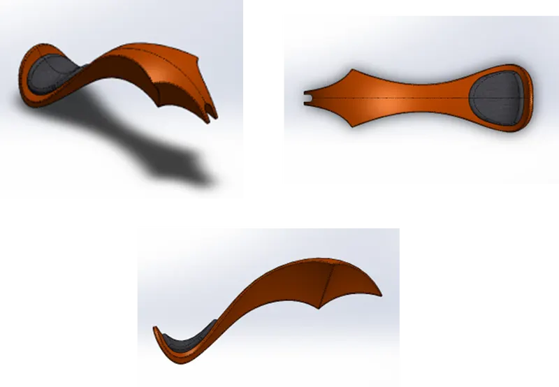
A safe reservoir for flammable fluids is a gas tank (or petrol tank). The term is usually applied to part of an engine structure in which the fuel is contained and pushed (fuel pump) or released (pressured gas) into an engine, but any holding tank for fuel may be called so.
Feature used:
- Sketch
- Trim
- Project curve
- Convert entities
- Sweep surface
- Loft surface
- Fill surface
- Surfaces trim
- Sweep cut
- Fillet
- Appearance
Lofted surface is a surface developed by several 3D curves or existing that create a smoot tangency between the curves chosen.
Swept surface are surface created along a path form from a segment curve.
Filled surface a surface patch with any number of sides is built the filled surface function, inside a boundary defined by existing model edges, sketches, or curves, including composite curves.
Surface knit the two free edges/ open edges of the surface are knit. It also eliminates the distance between the two surface edges.
13. GAS TANK
A safe reservoir for flammable fluids is a gas tank (or petrol tank). The term is usually applied to part of an engine structure in which the fuel is contained and pushed (fuel pump) or released (pressured gas) into an engine, but any holding tank for fuel may be called so.
Feature used:
- Sketch
- Trim
- Project curve
- Convert entities
- Sweep surface
- Loft surface
- Fill surface
- Surfaces trim
- Sweep cut
- Fillet
- Appearance
Lofted surface is a surface developed by several 3D curves or existing that create a smoot tangency between the curves chosen.
Swept surface are surface created along a path form from a segment curve.
Filled surface a surface patch with any number of sides is built the filled surface function, inside a boundary defined by existing model edges, sketches, or curves, including composite curves.
Surface knit the two free edges/ open edges of the surface are knit. It also eliminates the distance between the two surface edges.
GAS TANK
A safe reservoir for flammable fluids is a gas tank (or petrol tank). The term is usually applied to part of an engine structure in which the fuel is contained and pushed (fuel pump) or released (pressured gas) into an engine, but any holding tank for fuel may be called so.
Feature used:
- Sketch
- Trim
- Project curve
- Convert entities
- Sweep surface
- Loft surface
- Fill surface
- Surfaces trim
- Sweep cut
- Fillet
- Appearance
Lofted surface is a surface developed by several 3D curves or existing that create a smoot tangency between the curves chosen.
Swept surface are surface created along a path form from a segment curve.
Filled surface a surface patch with any number of sides is built the filled surface function, inside a boundary defined by existing model edges, sketches, or curves, including composite curves.
Surface knit the two free edges/ open edges of the surface are knit. It also eliminates the distance between the two surface edges.
ASSEMBLY OF AMMERICAN CHOPPER
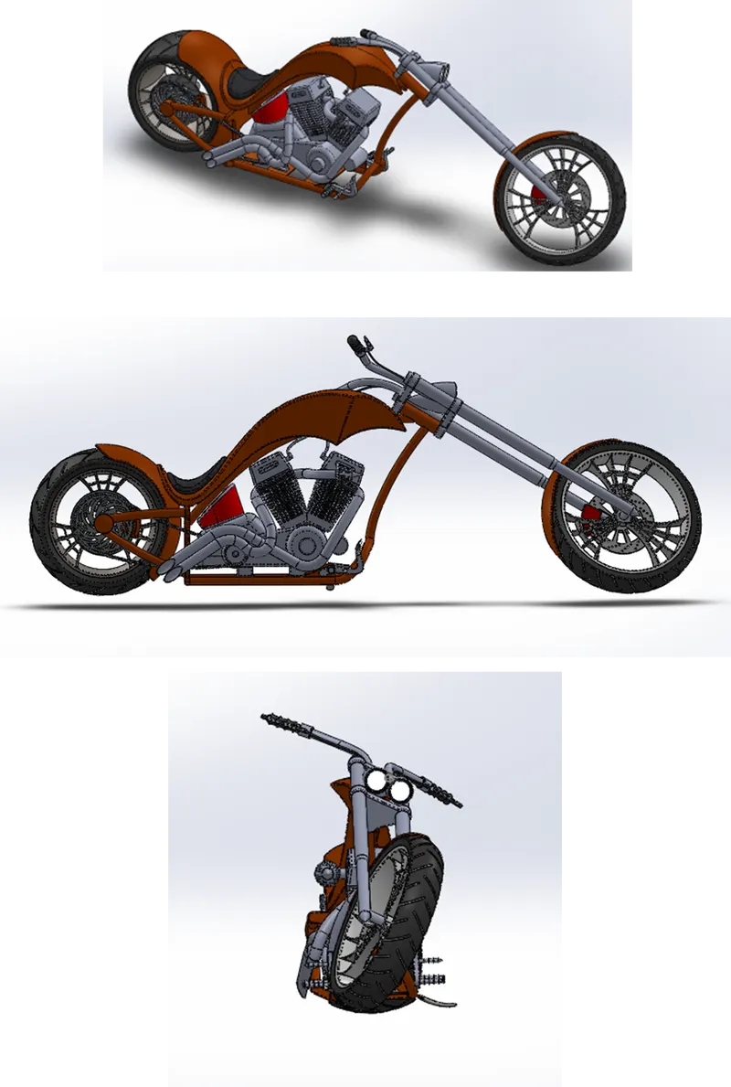
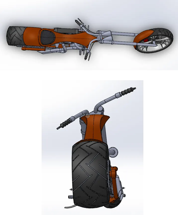
All the parts listed above are brought here to assemble them together to have the final look of the chopper we have designed part by part. We have used different types of mates so as to constraint the parts in its position.
Mates like coincident mate, concentric mate, tangent mate, parallel mate, width mate, distance mate, limit angle mate.
RENDERING
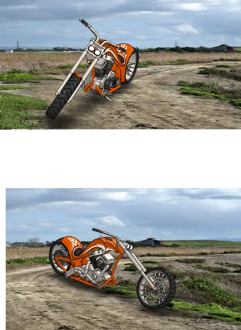
Rendering is the method of representing the designed model in a more realistic way in a realistic environment.
The rendering here had to be done using the photoview 360 and visualize solidworks.
CONCLUSION
Thus the designing and rendering of American chopper using solid-works is completed.