Design of an American Chopper and its Components.
Design of an American Chopper and its Components.
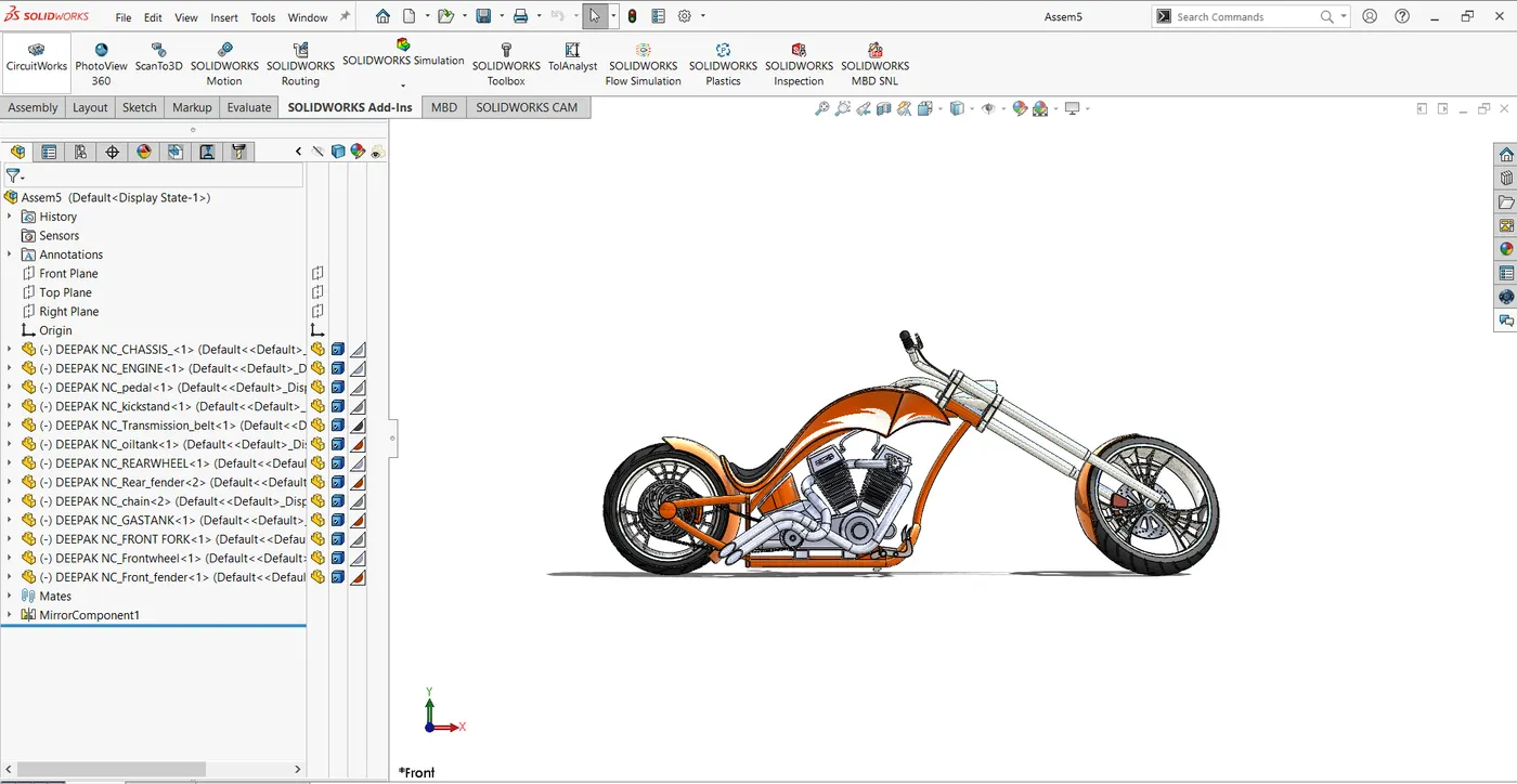
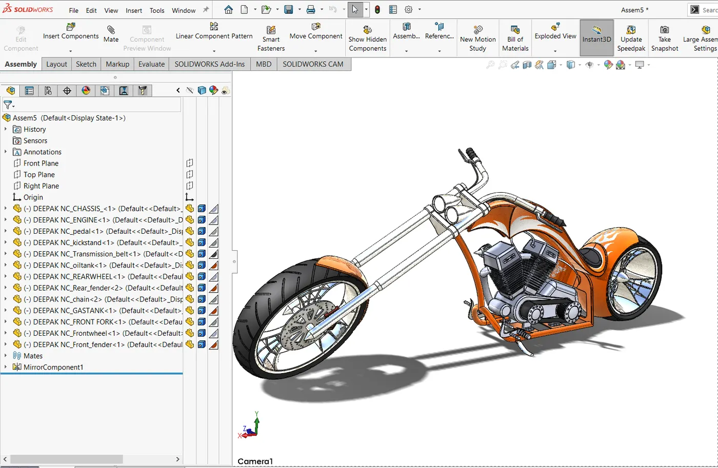
Objective: In this project, I generated the assembly of an American chopper and designed its components using Solidworks.
Introduction: Solidworks is a software owned by Dassault systems and it is a mechanical design automation application that lets designers quickly sketch out ideas, experiment with features and dimensions, and produce models and detailed drawings.
Solidworks has also other products which are part of it, like
CAM, Simulation, Circuit works, Electrical 3D, Visualize.
Design methodology/Approach:
The steps involved in designing American copper are as follows,
- Designing individual American chopper components.
- Assembly of an American chopper
- Apply decals
- Final rendering.
Designing of an American chopper involves 13 individual components.
- Transmission belt
- Kickstand
- Front fender
- Rear fender
- Oil tank
- Gas tank
- Chain
- Pedal
- Front-wheel
- Rear-wheel
- Front fork
- Chassis
- Engine
The steps or approach to be followed to create the 3D model.
- While designing the components the first thing you want to think about is the overall shape that you want to create so that you can use some of the features that will reduce the time and tedious work.
- Always use a reference to check your angles and proportion so you will get to check the model you are creating and can avoid conducting mistakes
- Always try to define the sketch completely, and try not to over define the sketch.
- Try to add relation in sketches so that the model won’t go off the design which is required.
- Check for the symmetric design of a model, if it is there, then design the only half of it and try to use the proper command in Solidworks to create the other half of it so that it will reduce the time required to design a component.
Description:
Following are the various feature and sketch tool that is mostly used in Solidworks

Feature tools

Sketch tools

Surface tools
Extrude Boss/Base: It extrudes a sketch in one or two directions to create a solid feature. Basically it adds material that gives 3D shape.
Cut extrude: It is used to remove the material of the required dimension. It cuts the solid model by extruding the sketch in one or two direction
Loft Boss/Base: A loft creates a feature by making transitions between two or more sketch profiles. When you create a loft, the sketch profiles must reside on different planes (or planar faces).
Shell: When you shell a part in SOLIDWORKS, selected faces are removed and thin faces of given or mentioned thickness remain on the rest of the part.
Fillet: When you create a fillet, you set the radius to determine the smoothness of the edges.
Swept Base/Boss: It creates a base of boss where the 2D sketch is projected along the mentioned 3D path.
Revolve: it is used to create and extrude around an axis by mentioning the axis of revolution where you can control the angle of revolution.
Thin feature: To extrude as thin feature.
Linear pattern: Linear Pattern is used to copy the original tab a specified number of times linearly. The linear pattern creates multiple instances of a selected feature along a linear path. When you make a linear pattern, you specify the number of instances and the distance between each tab.
Circular pattern: Circular pattern is used to copy the original tab a specified number of times in a circle pattern with a controlled angle.
Mirror: Mirror is used to copy the sketch, feature, or bodies about the plane or axis.
Dome: it is used to create the dome shape or elliptical shape on the body.
Extend Surface: It is used to extend the surface up to a certain distance.
Project Curve: It is used to form a 3D curve using two 2D curves.
Swept surface: It creates a surface by moving a 2D sketch along the 3D sketch path.
Split: It is used to split the one bod from the other and it can also be used to remove the additional bodies from one body by selecting consume cut bodies.
Revolve cut: It is used to remove the material around the axis as per the dimension.
Trim Lines: it is used to remove the unwanted lines.
Thicken: it is used to create the thick solid form the one or more adjacent surfaces.
Surface trim: It is used to remove the unwanted surface. It’s like the extrude cut.
Surface Knit: It is used to combine two or more adjacent and nonintersecting surfaces into a single surface body.
“Surface should be knitted properly before converting surface to solid”.
3D sketch: it is used to create the sketch irrespective of the plane.
Offset entities: It is used to offset the sketch, lines, and curves to a certain distance.
Convert entities: it is used to convert the selected edges and sketch entities into identical entities by projecting them onto the sketch plane or face.
Boundary Surface: It is used to create surfaces between the profiles.
Offset on surface: It is used to offset surface boundary edges and create a 3D sketch on the surface model.
Extrude surface: It extrudes a sketch in one or two directions to create a surface.
Revolve surface: Revolves a sketch around the axis to create a surface feature.
Swept surface: Sweeps a closed profile along an opened or closed path to creating a surface.
Lofted surface: Creates a lofted surface between two or more profiles or sketches.
Filled surface: patches a surface within a boundary defined by edges, sketches, or curves.
Ruled surface: Inserts ruled surfaces in a specified direction from edges.
Delete Face: Deletes faces from solid bodies/surface bodies to create surfaces.
Design of Components:
- Transmission belt
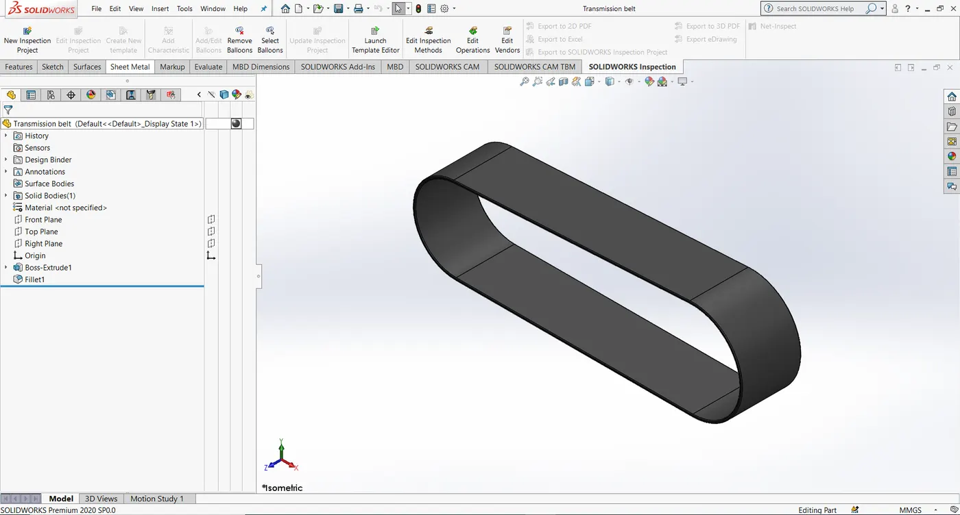
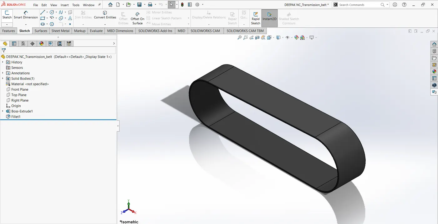
The sketch is created in the front plane, used extrude feature to form a solid body, and later fillets are applied to all the sides of an extrude later to give the appearance to the body.
- Kickstand
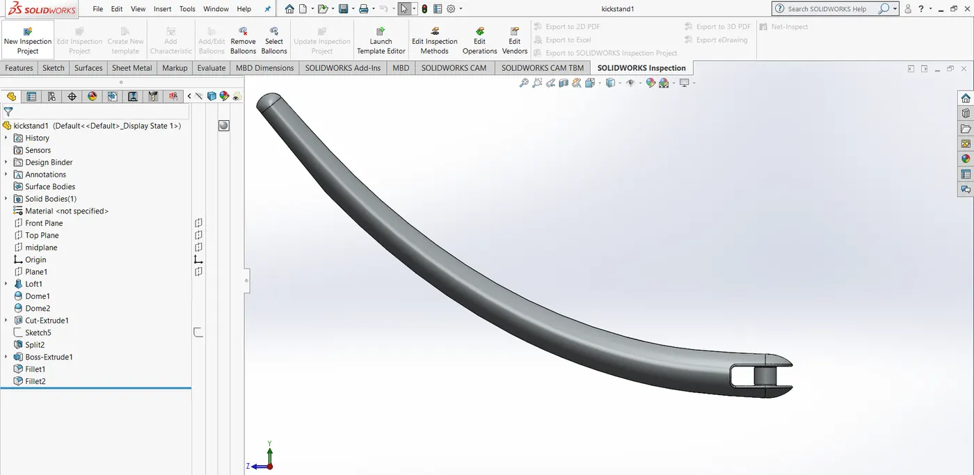
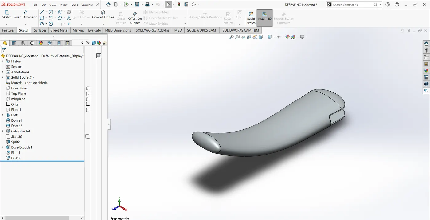
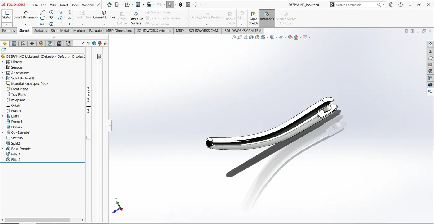
The sketch is created on the front plane and the right plane later created a new plane to create another sketch. After finishing sketch I used loft feature and dome feature to form a solid body and I used extrude cut to remove some portion of it later applied some fillets to give a proper appearance.
- Front fender
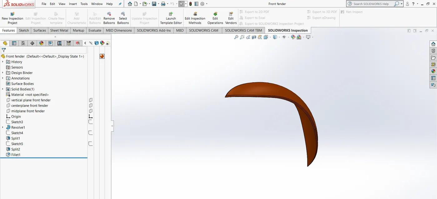
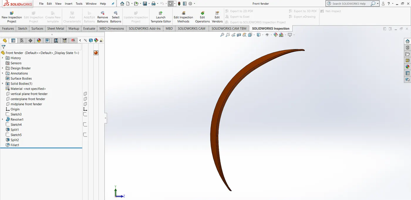
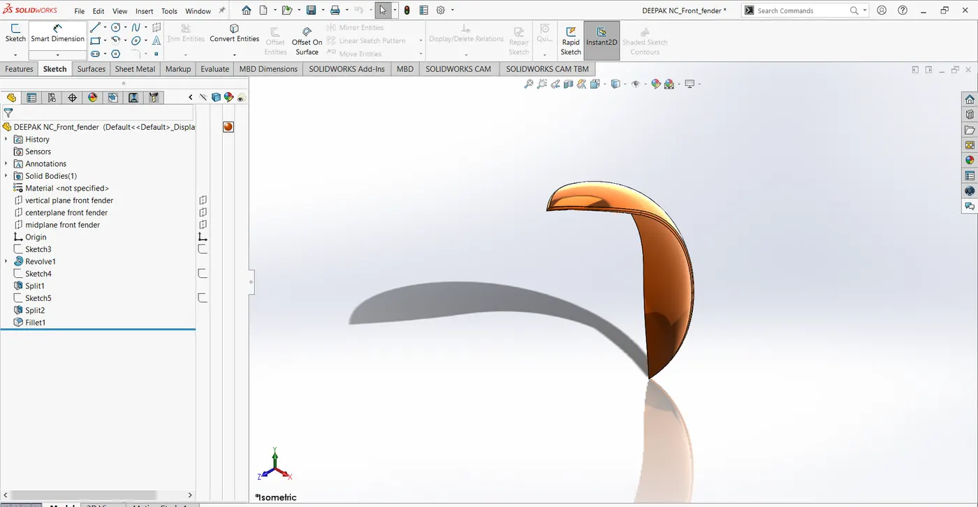
The sketch is created on the front plane and later features like Revolved Base/Boss, Extended entities, trim entities, Split, the fillet is used to give a final look, and to form a solid body.
- Rear fender
The sketch is created on the front plane and the revolve feature is applied for a certain angle to create a solid body.
Later split command is used to remove the unwanted material and fillet is applied to give a proper appearance.
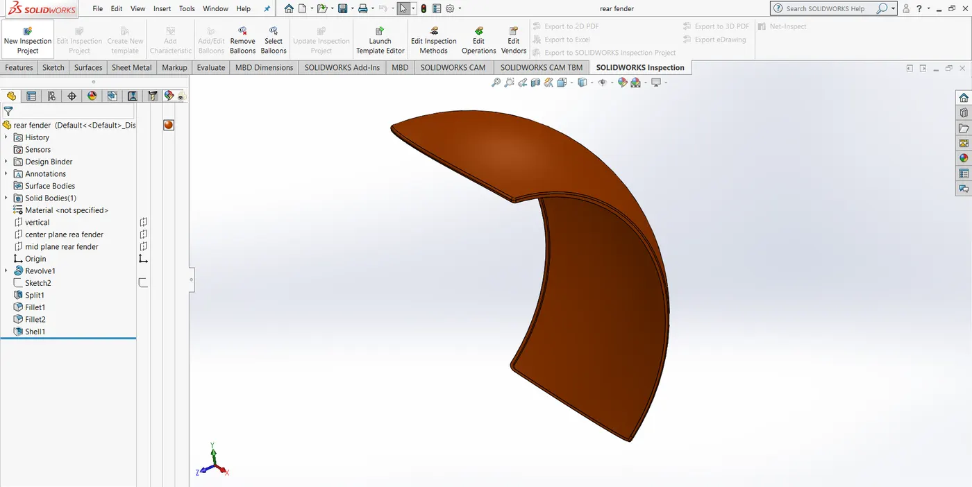
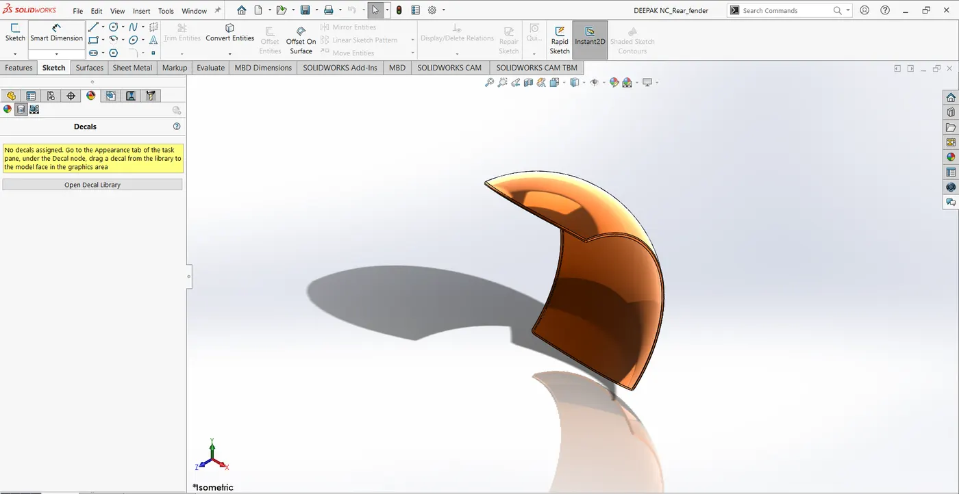
- Oil tank
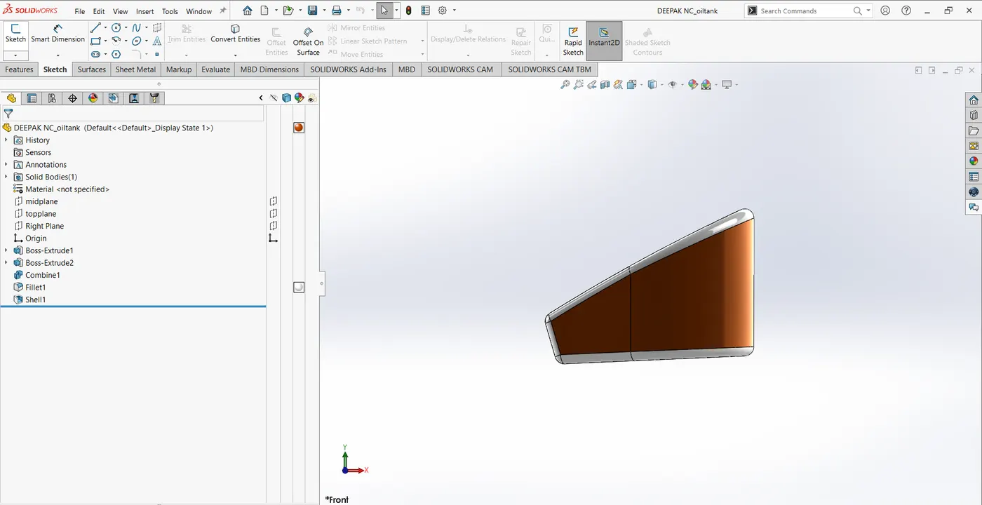
One sketch is created on the top plane and the other is created on the front plane. Later both the sketches are extruded and the combined feature is used to get the required body and fillet is used to give the final appearances.
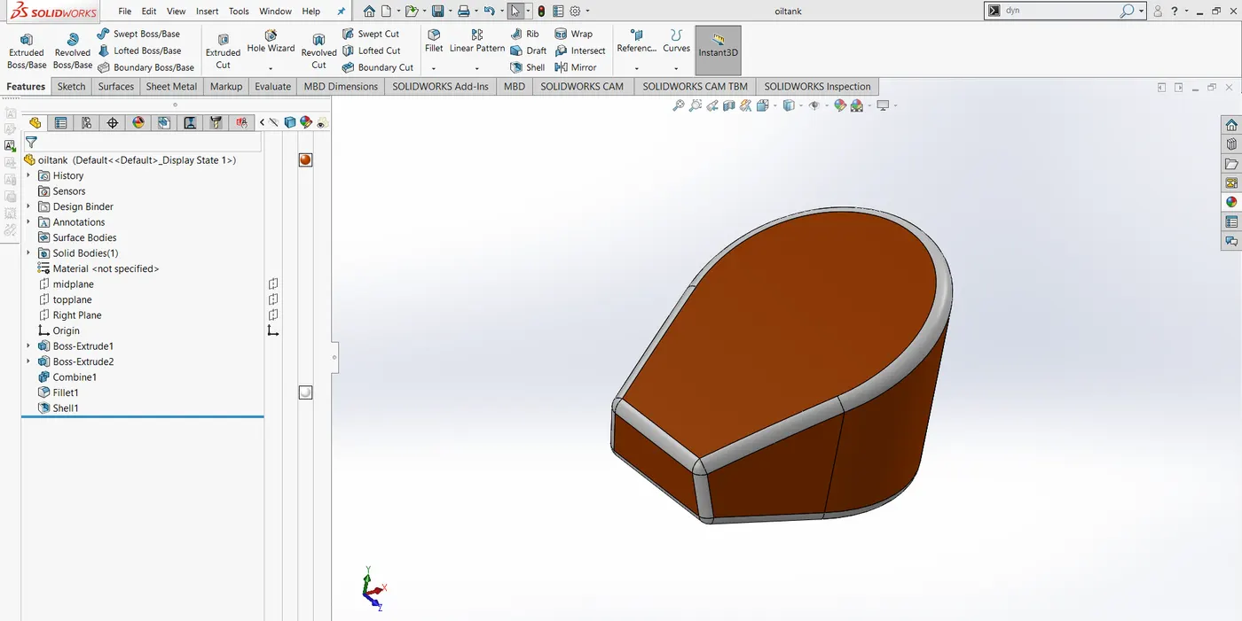
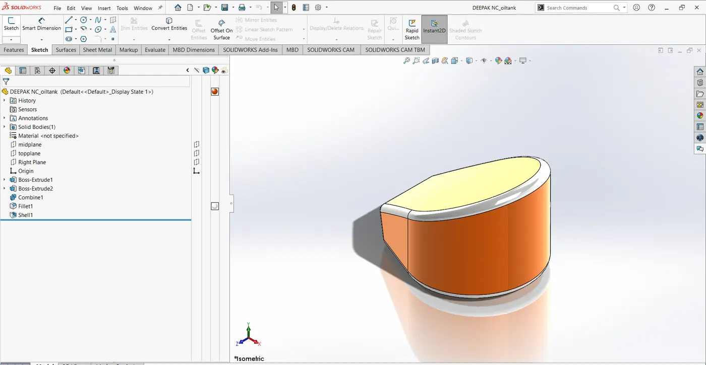
- Gas tank
First, insert blueprint of the bike and adjust the location, transparency as perused required.
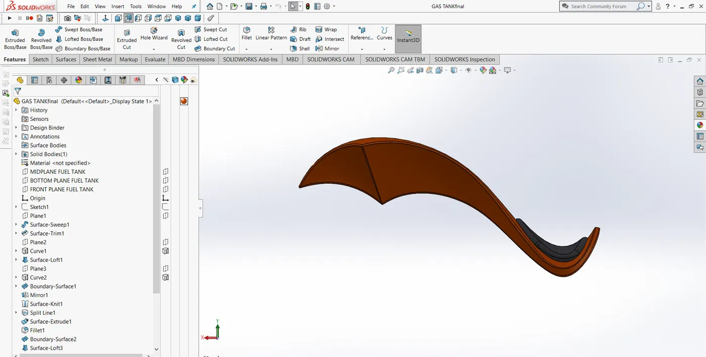
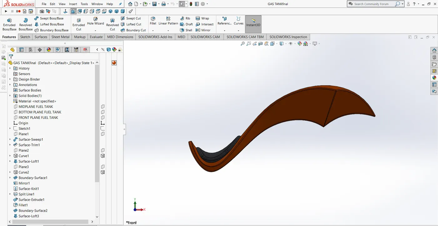
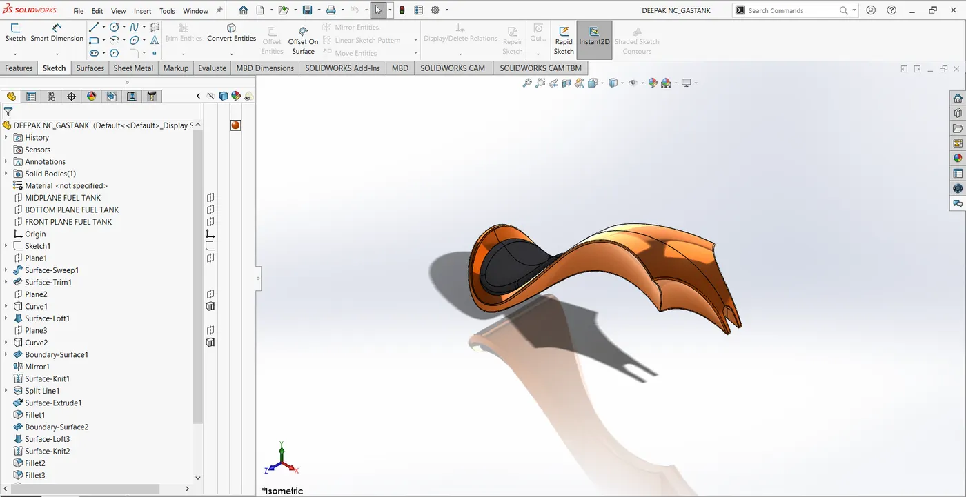
Draw the sketch and apply proper features to get the solid body of a Gas tank
The features involved in this are
Swept surface, loft surface, boundary surface, project curves, knit surfaces, combine, shell, Mirror, Fillet, Sweep cut, Convert and offset entities.
- Chain
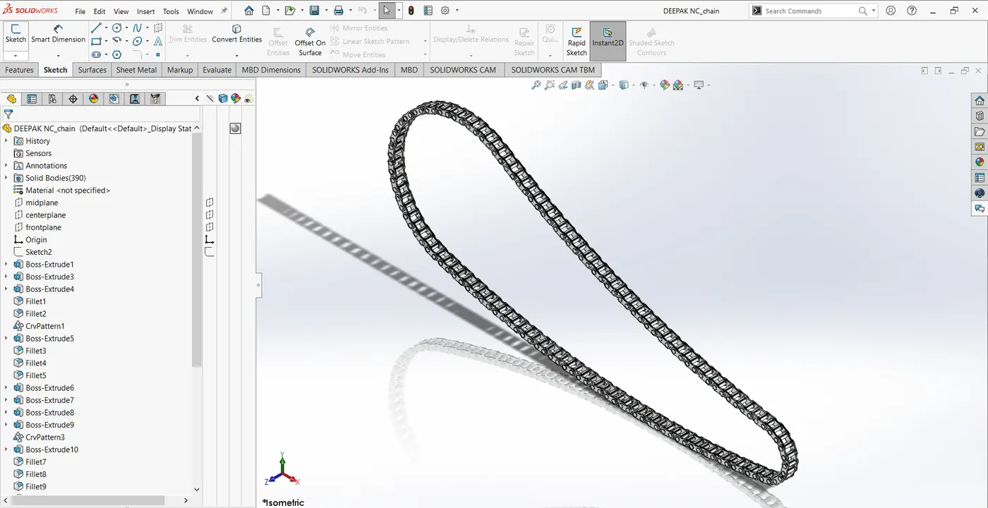
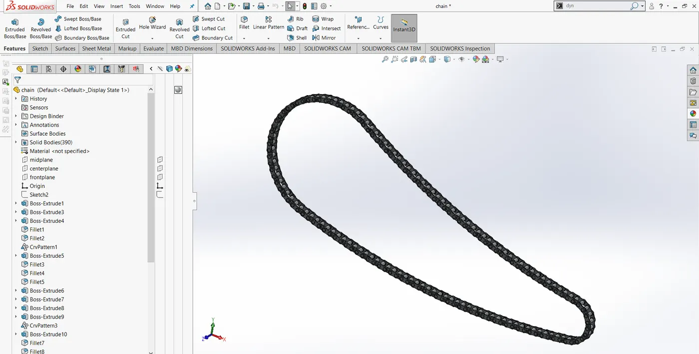
The sketch is created on the front plane, and also create a sketch for links which later saved as blocks.
Insert blocks and apply to coincide relation with the sketch and apply the extrude feature to create pins and plates for chains.
Use a curve driven pattern to get the required number of links on the curve.
- Pedal
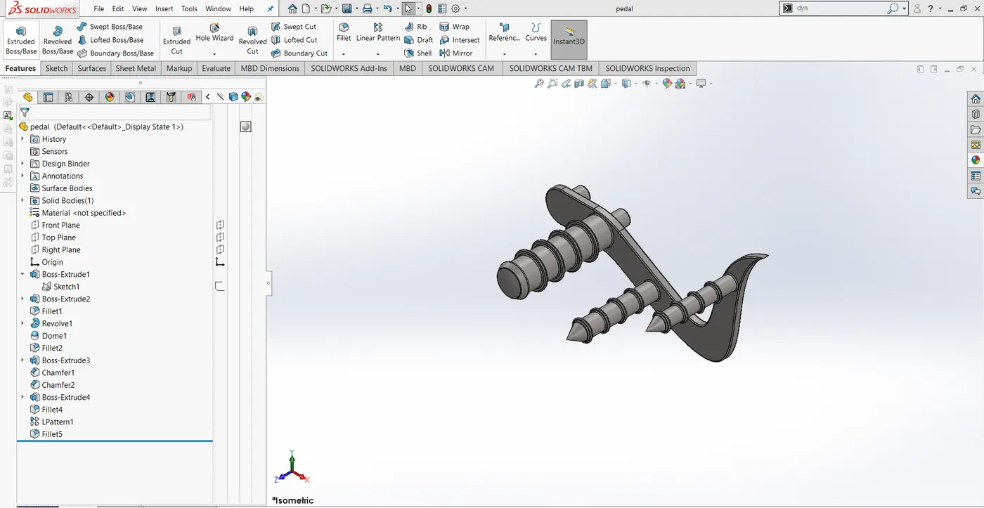
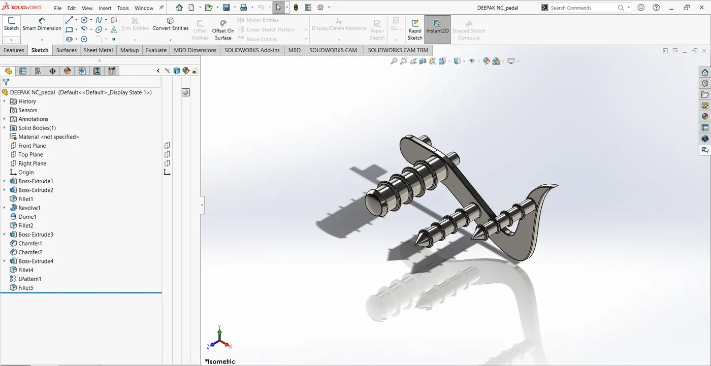
The sketch is created in the front plane and features like extrude and the dome is applied to create a solid body. Later Linear pattern and chamfer are used to create a final look of the body.
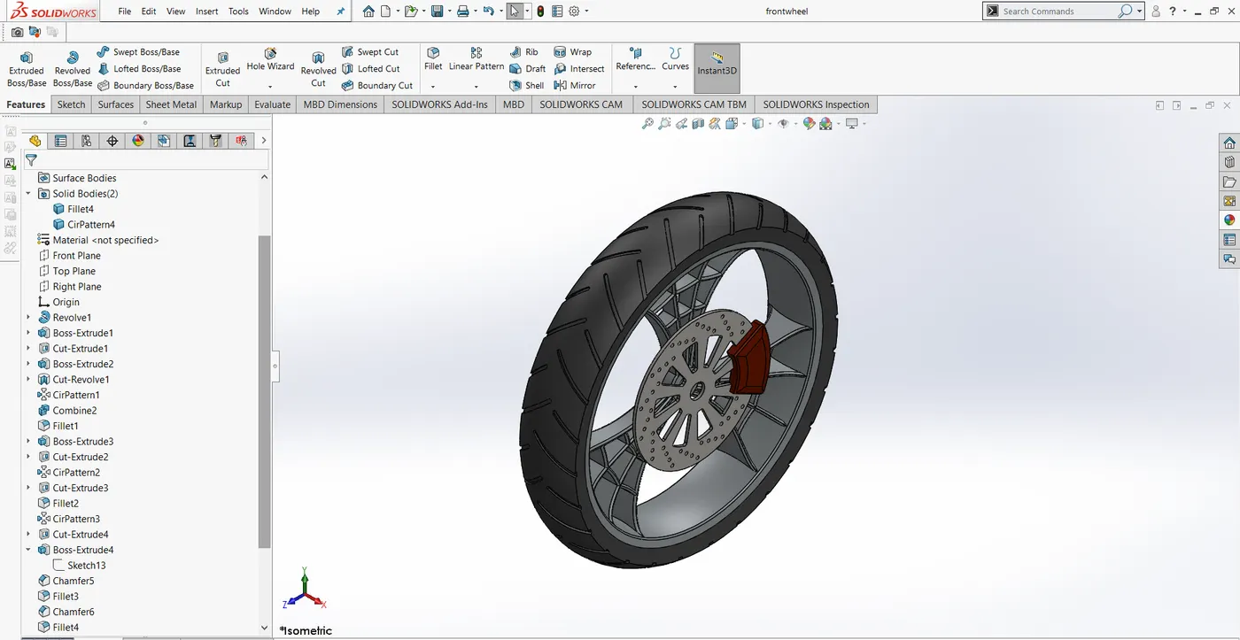
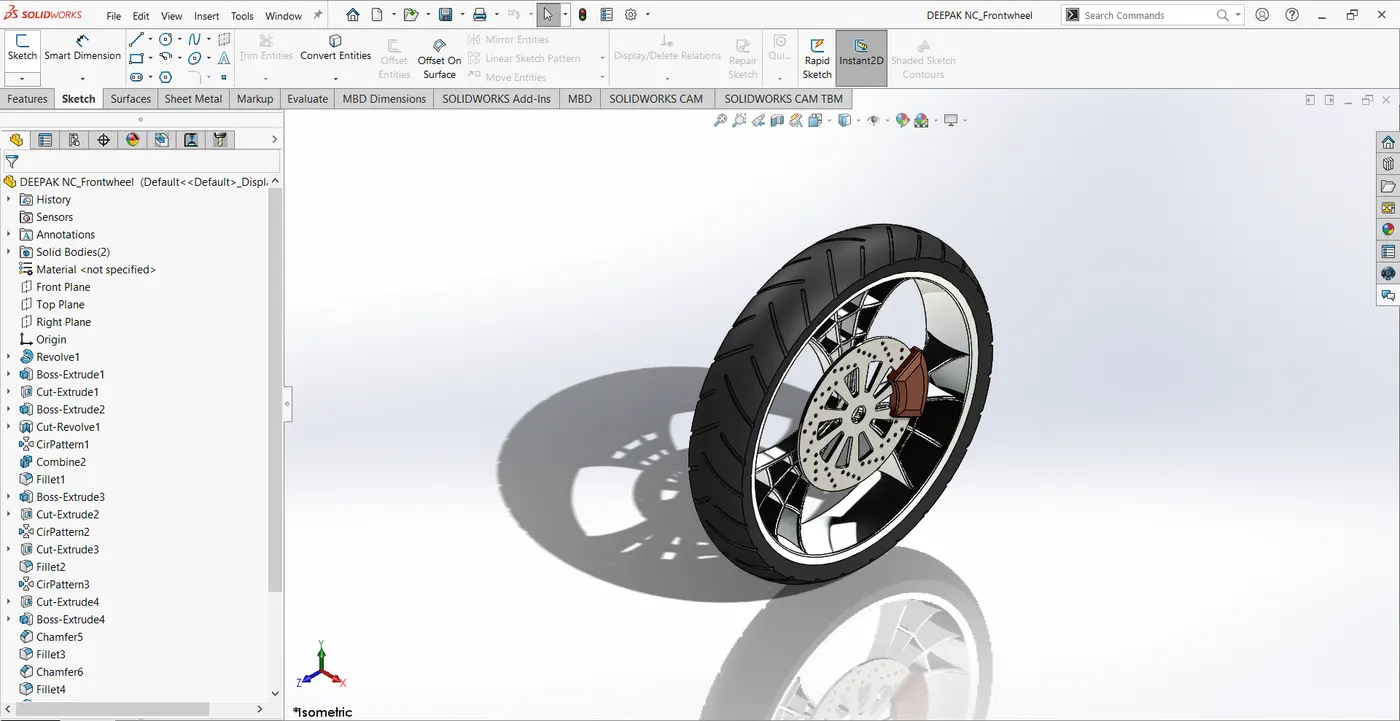
- Front-wheel
In this, I have actually created Rim, Rotor, Clipper, and Tire
The features involved in this are
Extrude Boss/Base, Cut extrude, Fillet, Revolve, Circular pattern, Mirror, Revolve cut, Trim Lines, Offset entities, Convert entities.
10 .Rear-wheel
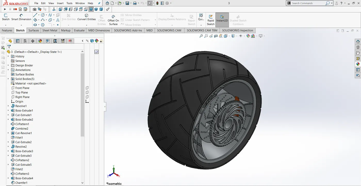
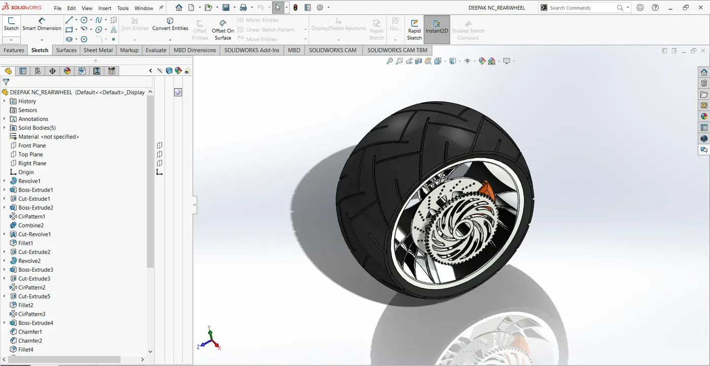
In this, I have actually created Rim, Rotor, caliper, sprocket, and tire.
The features involved in this are
Revolved Boss/base, extruded, Extrude cut, Revolved cut, Circular pattern, Mirror, Chamfer and fillet, Trim entities, offset entities, convert entities, and extend entities.
After creating the part the fine look is added by applying appearances.
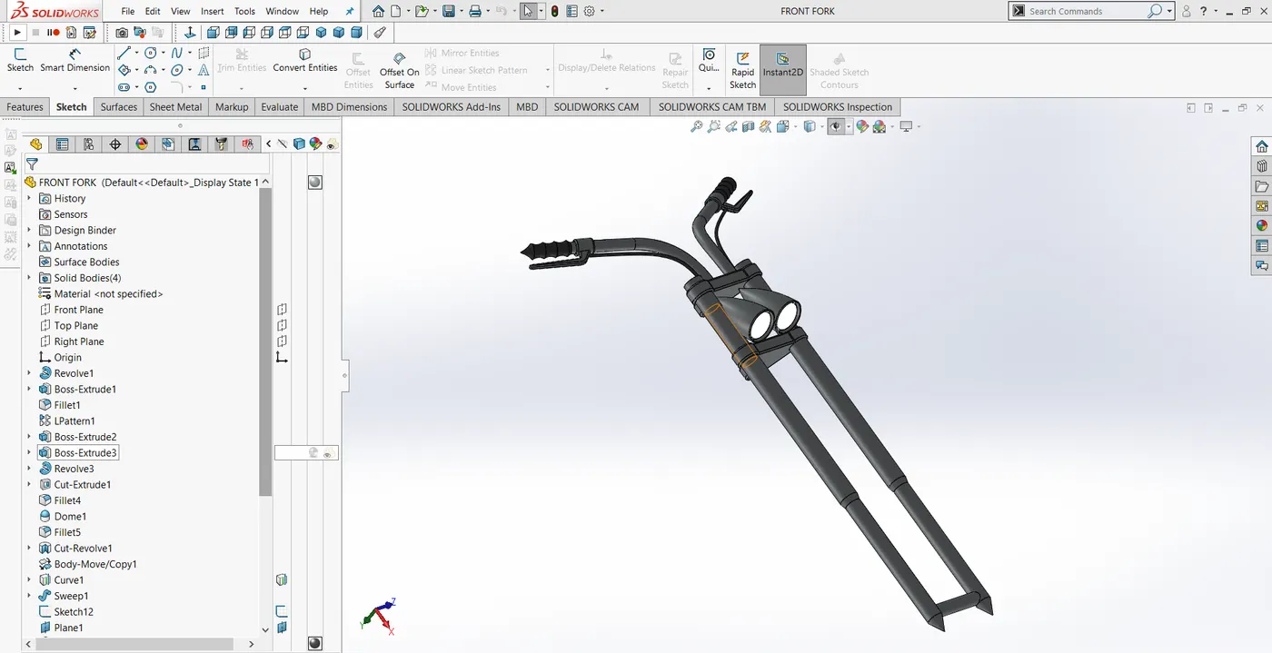
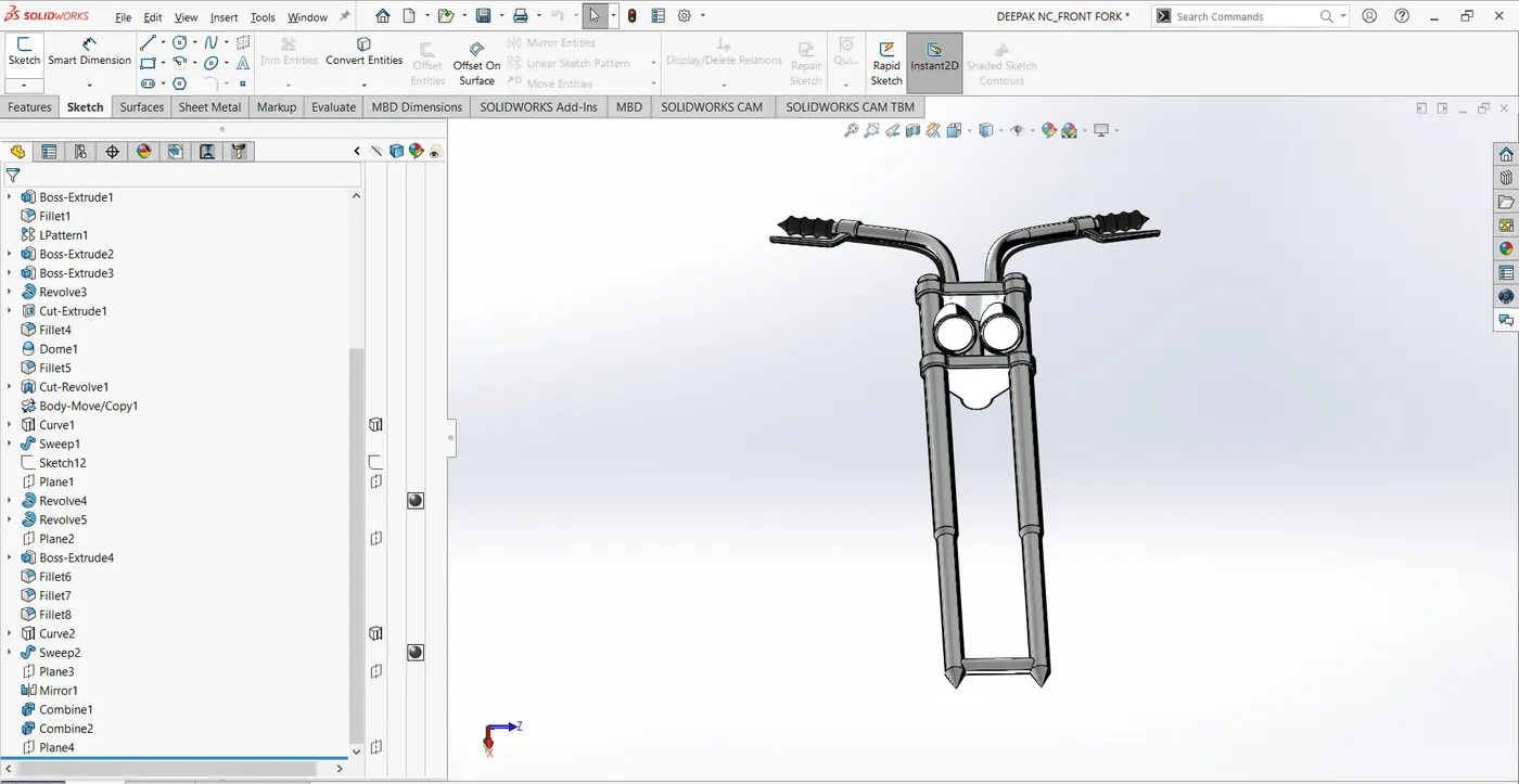
11.Front fork
In this only half of the sketch is created at the first and later it is mirrored about the axis using mirror (bodies) option.
Features used in this are
Extrude Boss/Base, Cut extrude, Dome, Revolve Cut, Project curves, Swept boss/base, Mirror, and Fillet.
12.Chassis
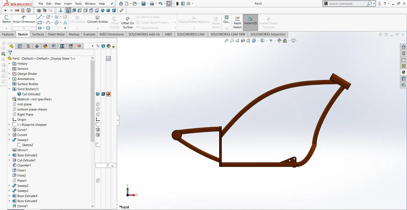
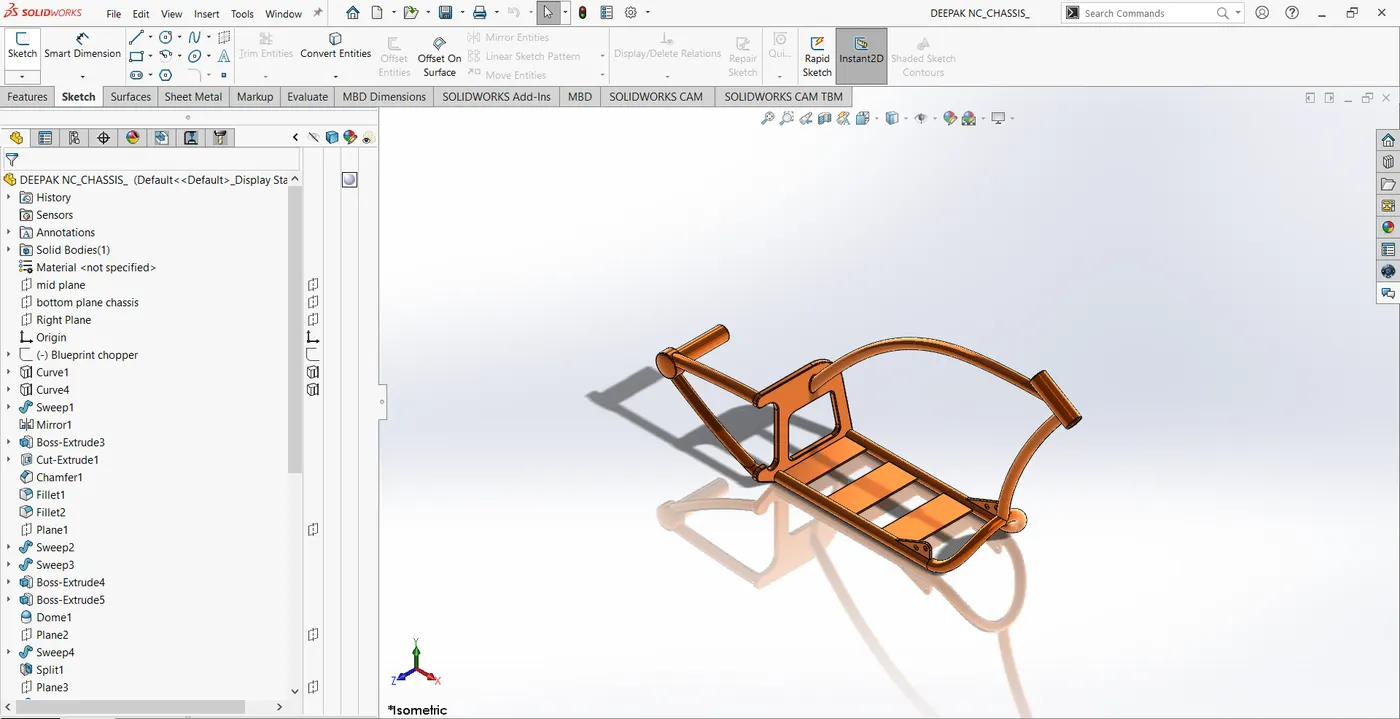
First, insert blueprint of the bike and adjust the location, transparency as perused required.
Draw the sketch and apply proper features to get the solid body of the Chassis.
The features used in this are
Extrude Boss/Base, Cut extrude, Dome, split, combine, chamfer, convert entities, offset entities, Project curves, Swept boss/base, Mirror, and Fillet.
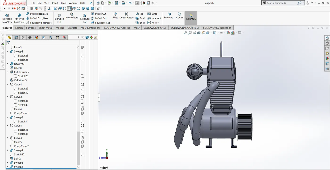
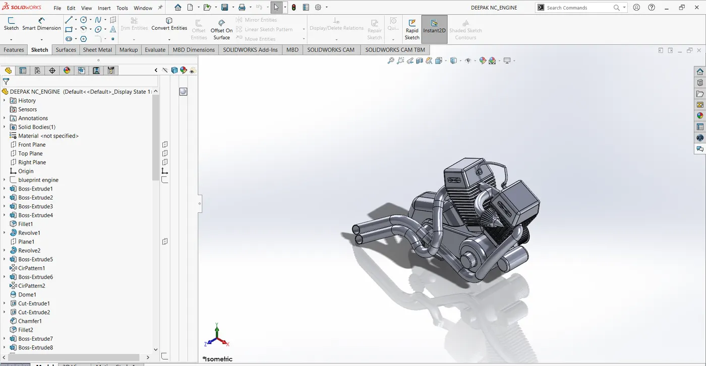
13.Engine
First, insert blueprint of the bike and adjust the location, transparency as perused required.
Draw the sketch and apply proper features to get the solid body of an Engine.
The features used in this are
Extrude Boss/Base, Cut extrude, Dome, split, Project curves, Composite curves, Swept boss/base, Mirror, and Fillet, convert entities, offset entities.
Assembly of the Components
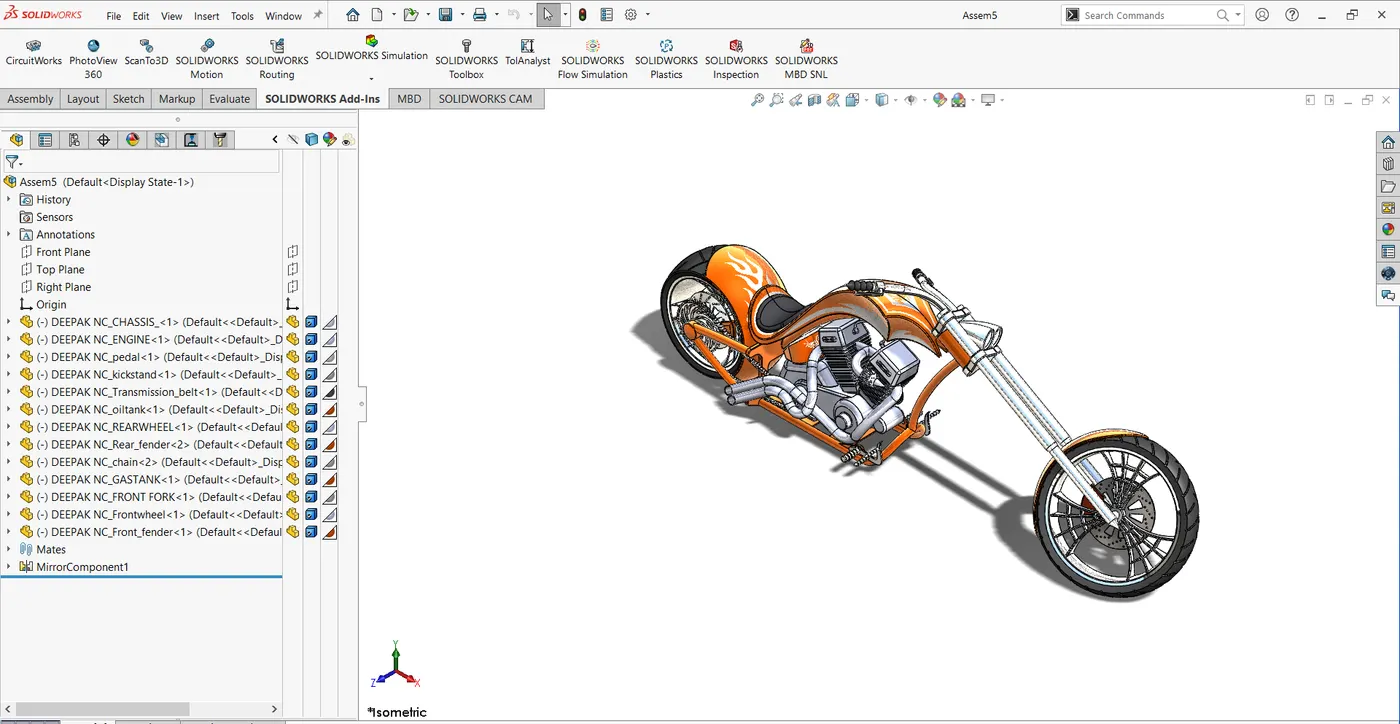
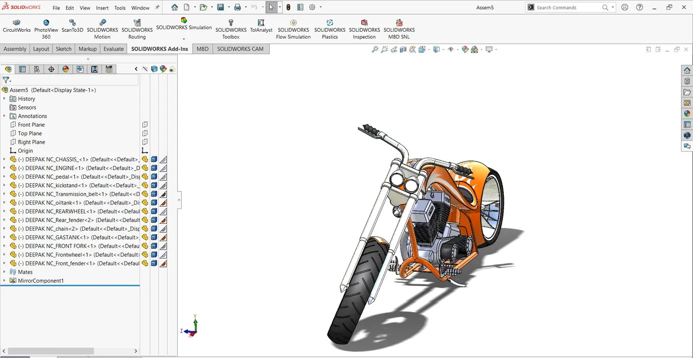
- Insert the components of an American chopper and place it as per user required.
- Rotate the components if required with respect to the view required.
- Apply the mates as required for proper alignment.
- Apply Decals once the assembly is completed.
Types of mates used are as follows
Width mate, Distance mate, concentric mate, coincident mate, angle mate.
File link: https://drive.google.com/drive/folders/1EVhNG7X1kD_jjymdy2U6matfOsLPWBAJ?usp=sharing