Photo Realistic Rendering
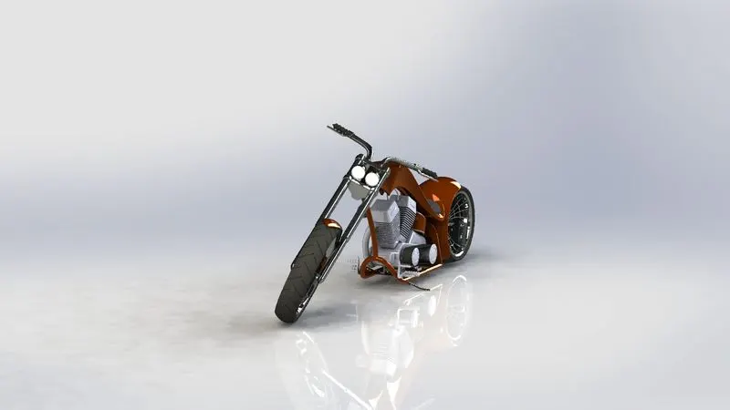
MODELLING AND RENDERING OF AMERICAN CHOPPER
INTRODUCTION:
SolidWorks is a solid modeling computer-aided design and computer-aided engineering application.
It helps the designers quickly sketch out ideas, experiment with features and dimensions, and produce
models and detailed drawings.This project focus on the modelling and rendering of American chopper.
OBJECTIVE:
To create chopper by using different features and sketching techniques.The major steps required are-
STEPS REQUIRED FOR THE DESIGN:
- Open a new file
- Selection of new plane
- Sketch as per dimension
- Surface modelling or solid modelling
- Applying required commands
- Save the model
MODELLING:
THE AMERICAN CHOPPER CONSISTS OF THE FOLLOWING PARTS
- Chassis
- Engine
- Front fork
- Pedal
- Chain
- Oil tank
- Gas tank
- Transmission belt
- Front fender
- Rear fender
- Front wheel
- Rear wheel
- Kick stand
WEEK 1:
PARTS: 1.Transmission belt 2.Kick stand 3.Front fender
Commands used:
- Lines and circles
- Extrude boss
- Lofted boss
- Dome
- Fillet
- Extrude cut
- Split body
- Revolve boss
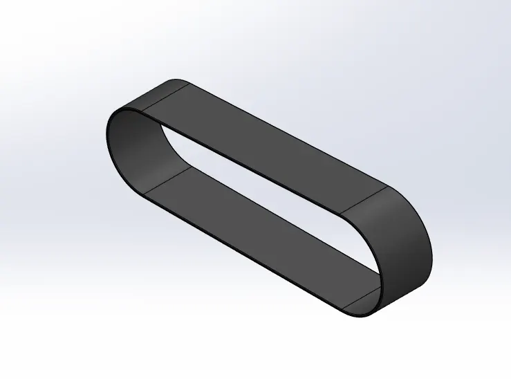
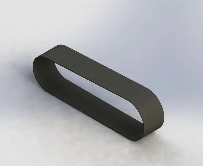
1.TRANSMISSION BELT
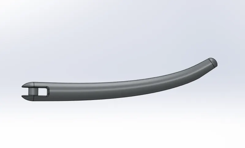
2.KICK STAND

3.FRONT FENDER
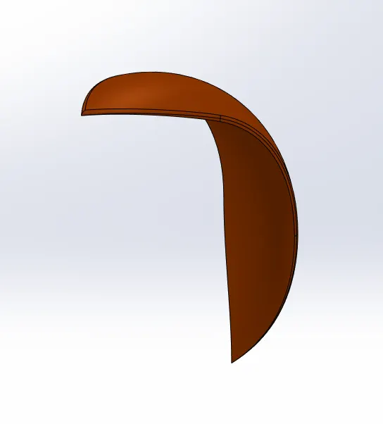
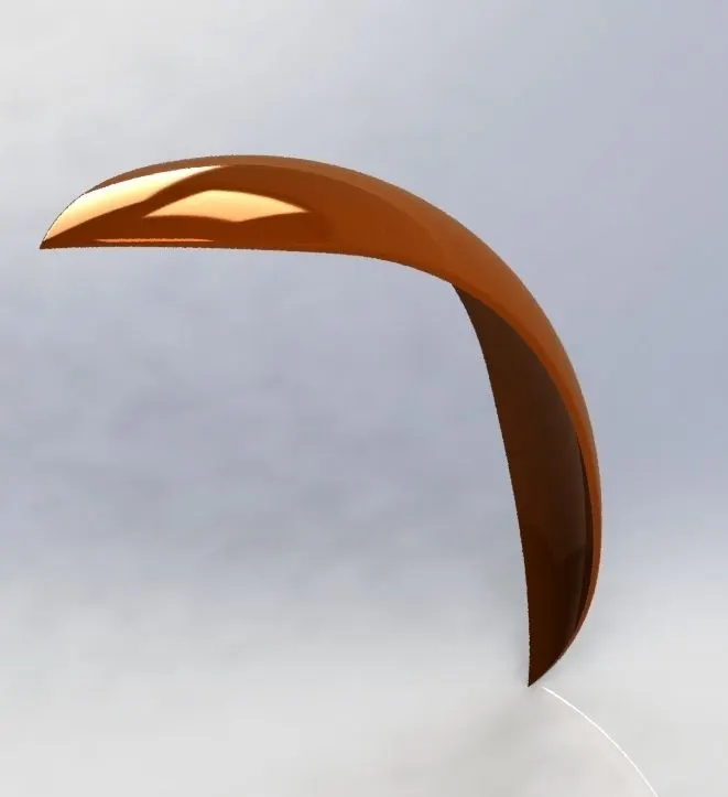
The above mentioned commands are used to design the week 1 parts for the chopper and the dimensions and instructions
are followed as per the week 1 video.Most of the solid modelling tools are used to design the above parts.
WEEK 2:
PARTS: 4.Oil tank 5.Chain 6.Pedal
Commands used:
- Sweep
- Revolve boss
- Splines
- Trim
- Extrude cut
- Extrude boss
- Shell
- Fillet
- Pattern types
- Split body
- Combine
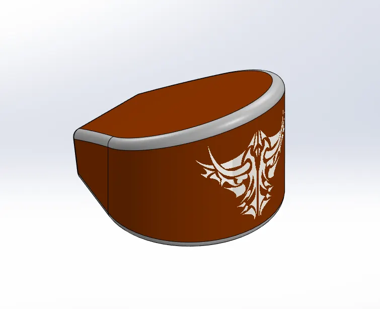
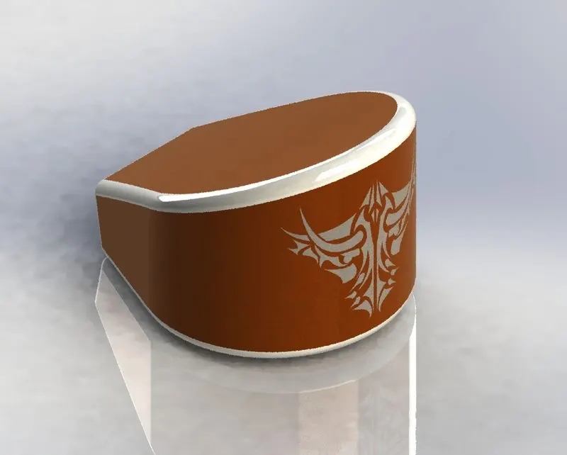
4.OIL TANK
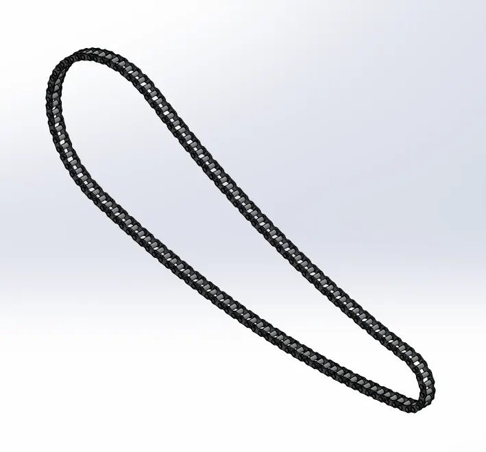
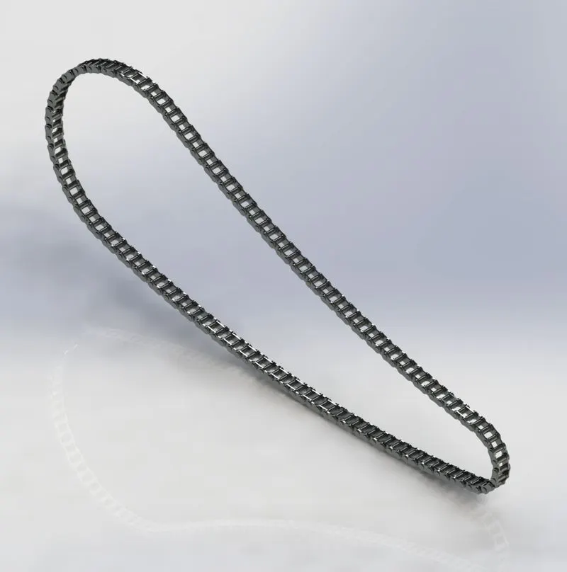
5.CHAIN
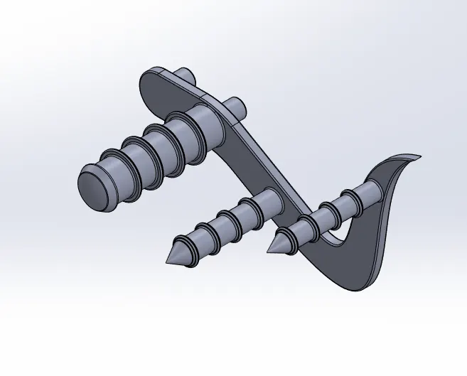
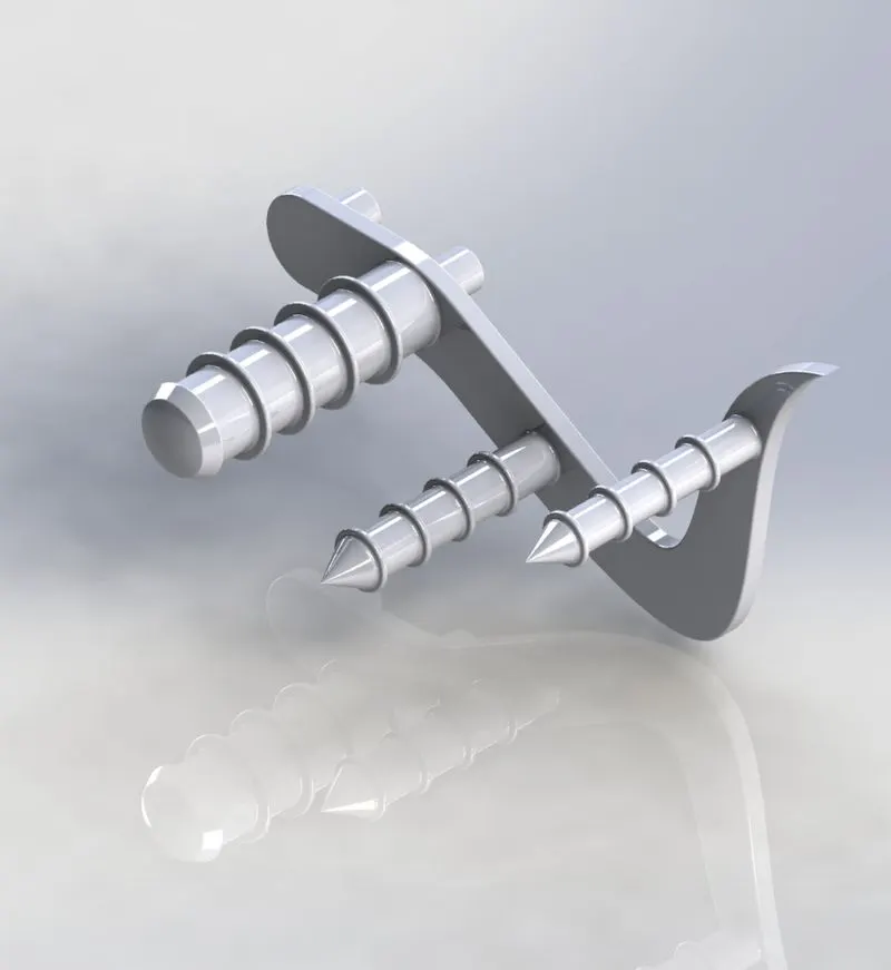
6.PEDAL
In the oil tank there are two solid bodies created and are combined to a sigle body by using combine feature.Then fillets are
are added and shell to give inner spacing.To create the chain two chain links are saved for easy operation dimension as per
the week 2 video.The above following commands are used to design to make the week 2 parts.The dimensions and intructions
are followed as per the week 2 video.
WEEK 3:
PARTS: 7.Front wheel
Commands used:
- Sweep
- Revolve cut
- Circular pattern
- Combine
- Extrude cut
- Revolve boss
- Chamfer
- Fillet
7.FRONT WHEEL
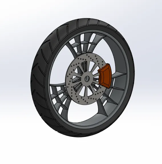
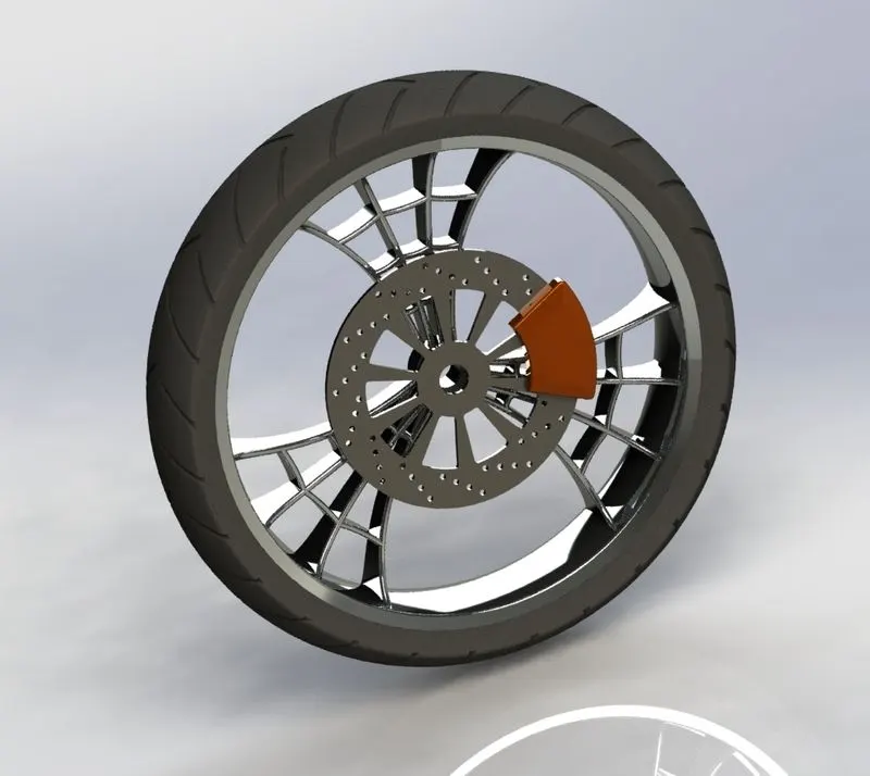
In front wheel we are using the circular pattern for making spider web design for the rim.Revolve cut is also used on the rim
for better surface finish.The above following commands are used to design the week 3 parts and the dimensions and instruction
are followed as per week 3 video.
WEEK 4:
PART: 8.Rear wheel 9.Front fork
Commands used:
- Sweep
- Revolve boss
- Mirror pattern
- Dome
- Projected curve
- Combine
- Chamfer
- Extrude boss
- Fillet
8.REAR WHEEL
9.FRONT FORK
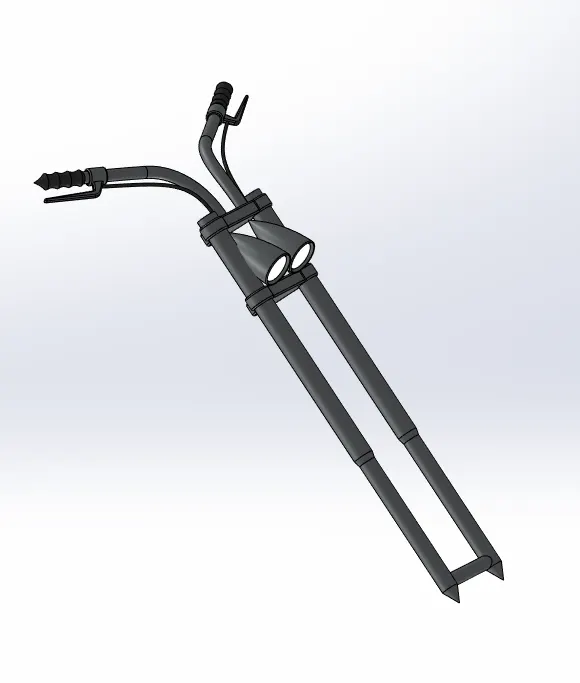
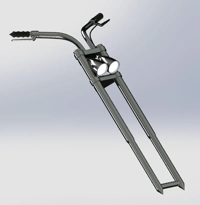
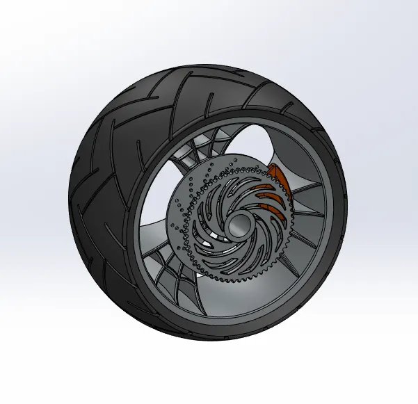
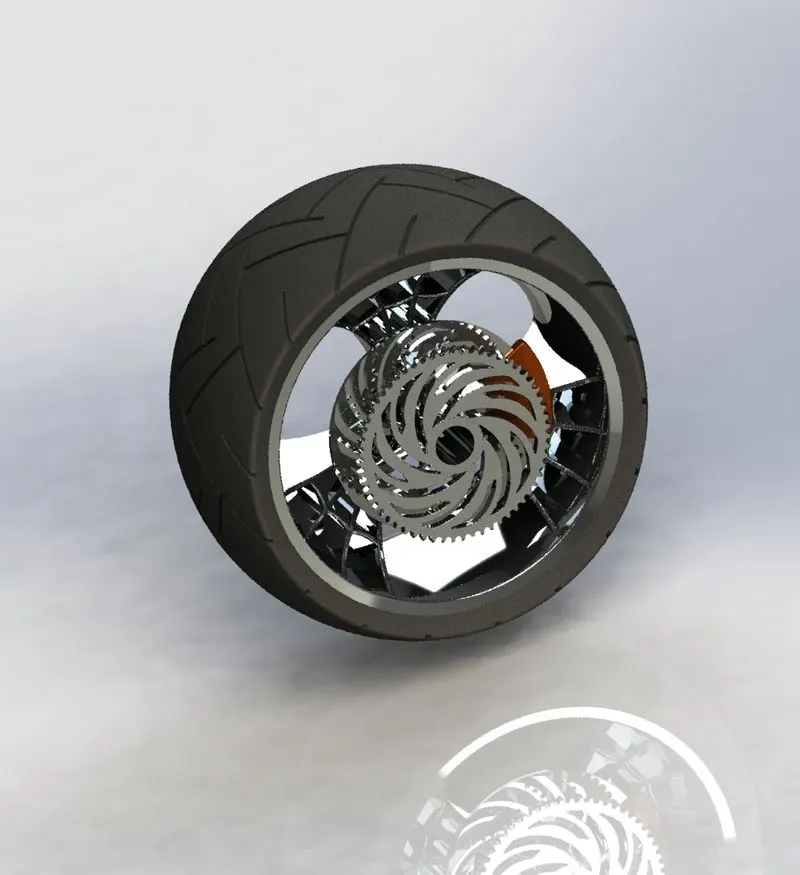
The rear wheel similar to the front wheel apart from the size. Here the front wheel chain sprocket is the additional part used. The usage
of projected curve and sweep is given for a better finish on the handle of the front fork. Mirror pattern is also used to complete the
other side .The above following commands are used to design to make the week 4 parts and the dimensions and instructions are
followed as per the week 4 video.
WEEK 5:
PARTS: 10.Chassis 11.Engine
Commands used:
- Sweep
- Revolve
- Extrude
- Dome
- Projected curve
- Split
- Mirror
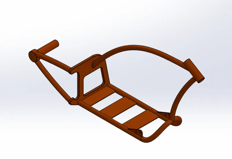
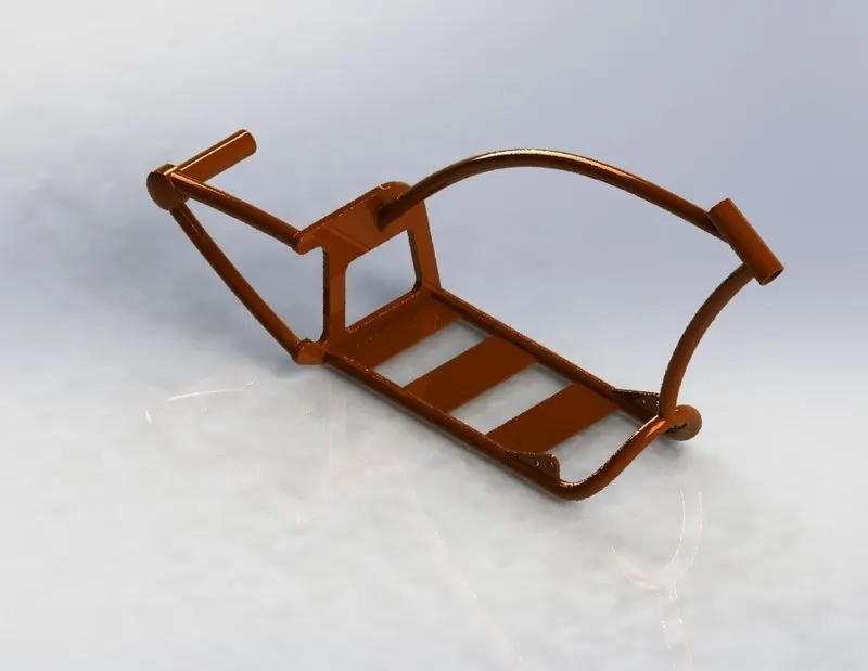
10.CHASSIS
11.ENGINE
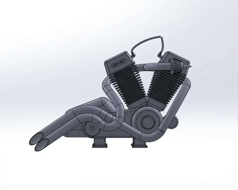
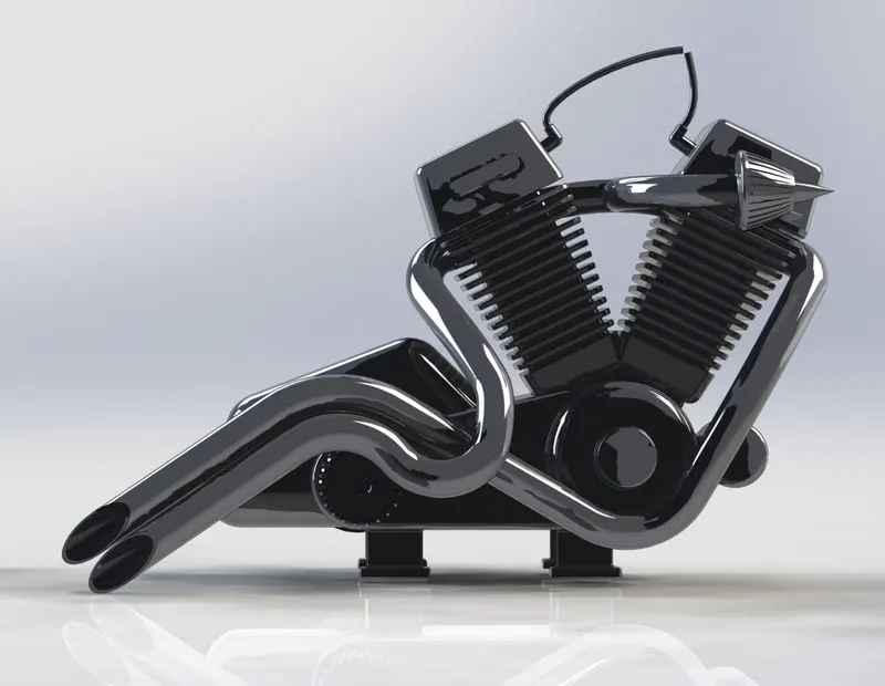
In the chassis model sweep and projected curves are used for the surface modelling to give a better finish.We also use the blue print
of the chopper to get a better view of the chassis.The projected curves are used to make the engine exhaust, most of the solid modelling
features are used to finish the engine.The above mentioned commands are used to design the week 5 parts and the dimensions and instructions
are followed as per the week 5 video.
WEEK 6:
PARTS: 12.Gas tank
Commands used:
- Surface loft
- Surface Sweep
- Boundary surface
- Revolve boss
- Extrude cut
- Knit surface
- Projected curve
- Split
- Cut sweep
- Fillet
- Surface trim
12.GAS TANK
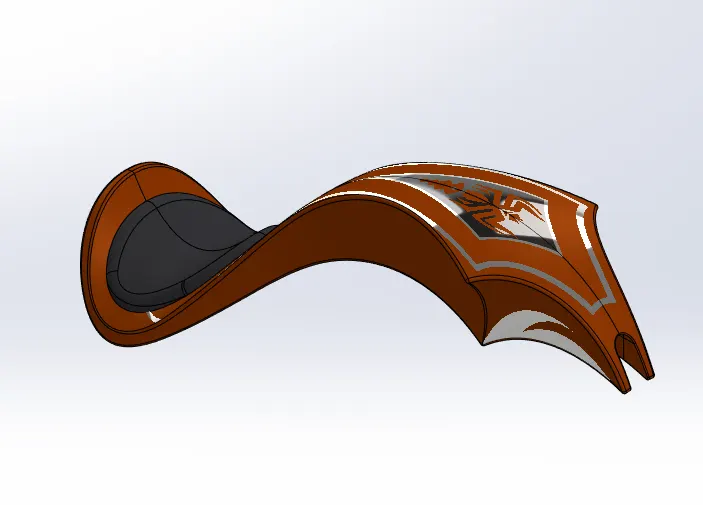
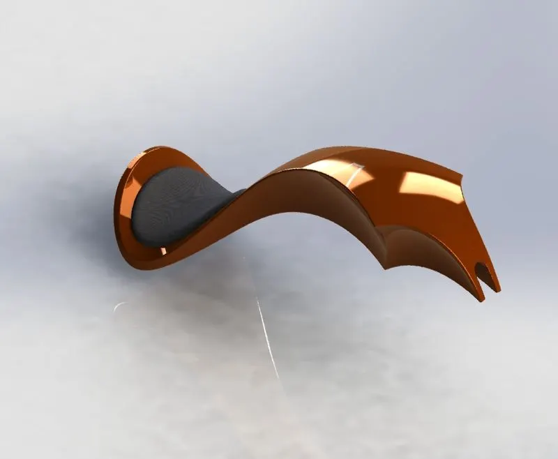
In the gas tank both solid and surface modelling tools are used for better finish.The above following commands are used to design the week 6 parts
and the dimensions and instructions are followed as per the week 6 video.
Once the parts are done ,material for each part are given by appearance option in solidworks. Material selction gives the parts more realistic outlook
of the product.
ASSEMBLY OF AMERICAN CHOPPER:
To make the assembly of American chopper we use mates
- Concentric mate
- Parallel mate
- Angle mate
- Distance mate
- Advanced mate
ISOMETRIC VIEW OF ASSEMBLY
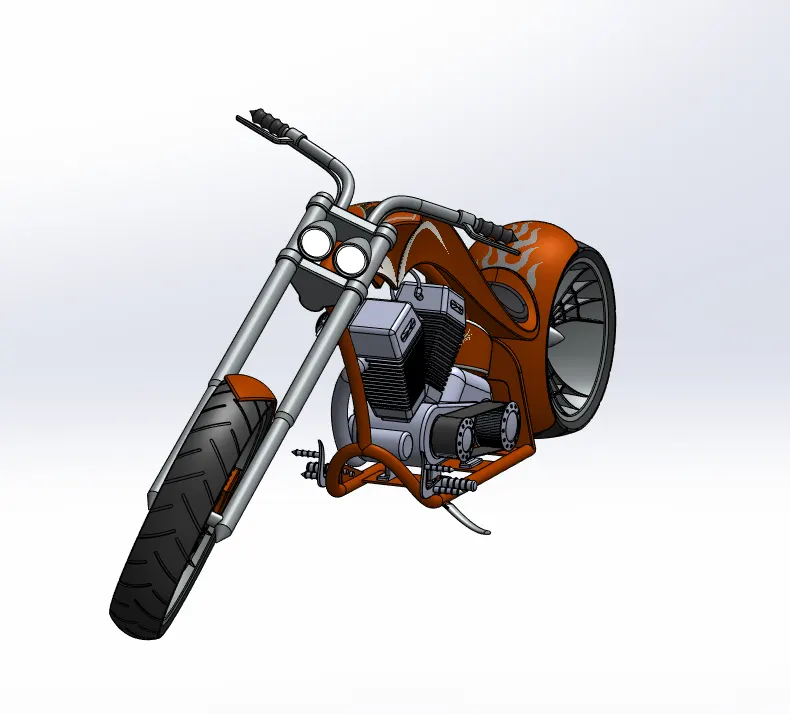
FRONT VIEW OF ASSEMBLY
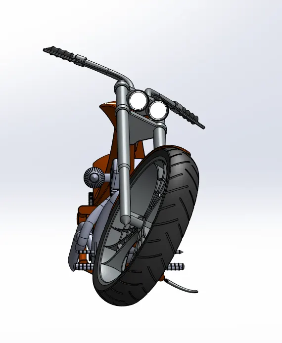
SIDE VIEW OF ASSEMBLY
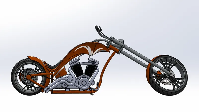
TOP VIEW OF ASSEMBLY
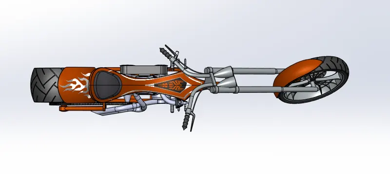
REAR VIEW OF ASSEMBLY
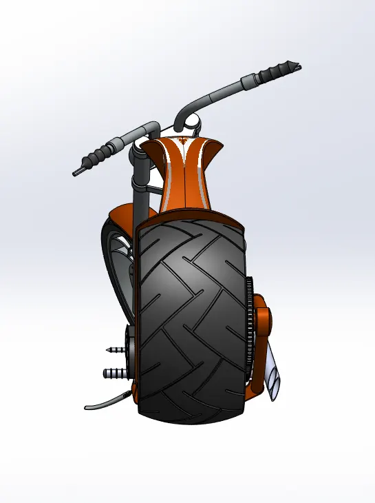
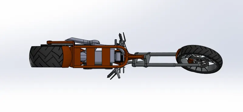
BOTTOM VIEW OF ASSEMBLY
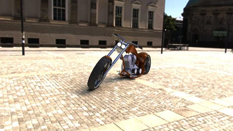
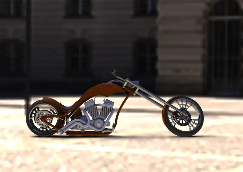
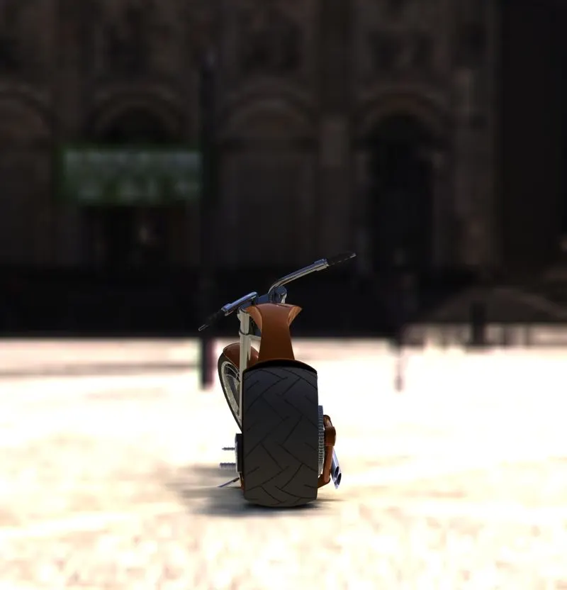
PHOTOVIEW360 RENDERING
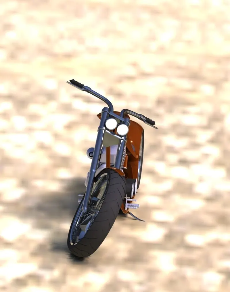
To make the chopper more realistic we use the PHOTOVIEW360.
Commands used:
- Camera
- Decals
- Edit scene
- Light
ISOMETRIC VIEW
FRONT VIEW
SIDE VIEW
REAR VIEW
CONCLUSION:
Modelling,assembly and rendering of an American chopper is successfully done by SOLIDWORKS.