Photo Realistic Rendering
AIM: In this project we are going to model and assemble various parts of American chopper bike.
TOOL: Solidworks 2020
INTRODUCTION:
A chopper is a type of custome motorcycle that emerged in the late 1950's in california. A chopper employs radically modified steering angles and lengthened fork for a streched out appearance. some of the characteristic features of the choppers are long front ends with extended forks often coupled with an increased rake angle, hard tail frames, very tall "ape hanger" or very short "drag" handledbars, lengthened or streched frames and larger than stock front wheels.
OBJECTIVE:
To design a different parts of american chopper using solidworks 2020
To assemble these parts modeled for the chopper
And to create a photorealistic model of a chopper and render the model using photoview360.
FOLLOWING PARTS MODELED FOR THE CHOPPER:
1. Transmission belt
2. Kickstand
3.Front fender
4.Rear fender
5.Oil tank
6.Chain
7.Pedal
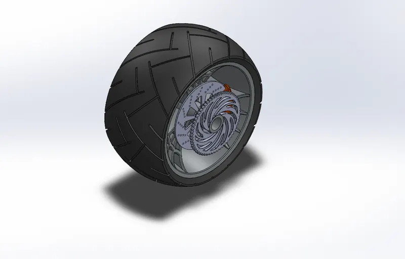
8.Front-wheel
9.Rear-wheel
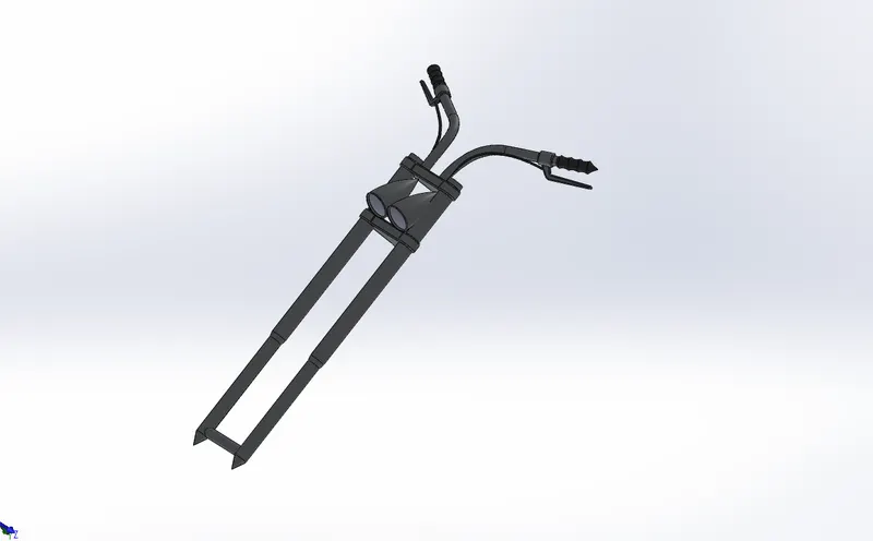
10.Front fork
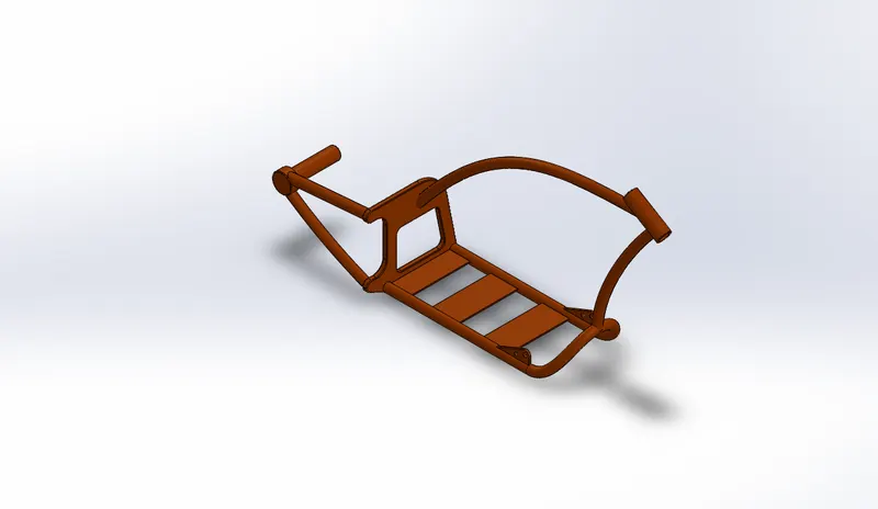
11.Chasis
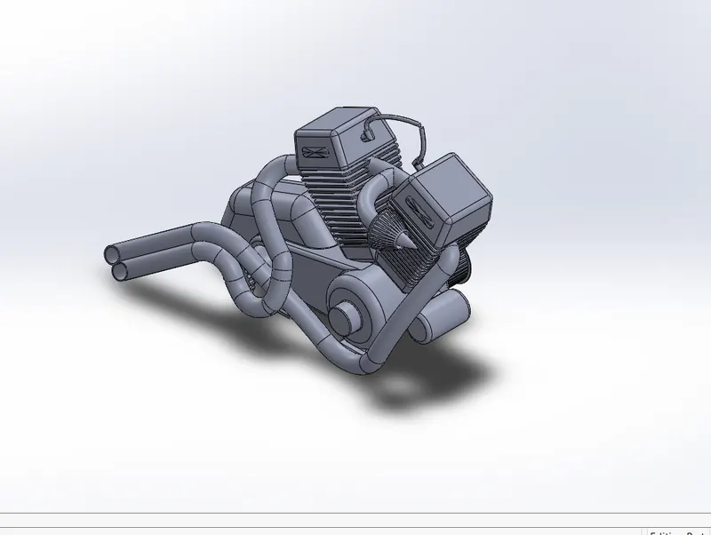
12.Engine
13.Gas tank
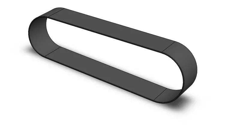
1.TRANSMISSION
The transmission belt in the chopper is used to transmit the power from the engine to the gearbox.
Commands used:
2d sketch
offset entities
extrude
fillet
appearance
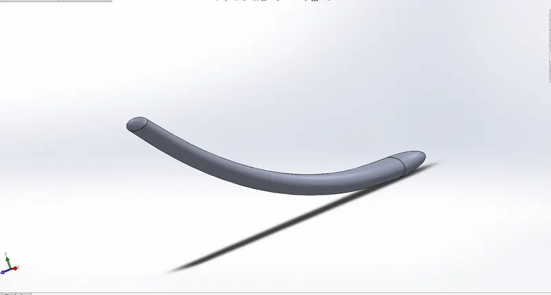
2.KICKSTAND
The kick stand is used to support a chopper.
Commands used:
2d sketch
spline
extrude
loft
dome
cut-extrude
split
fillet
appearances
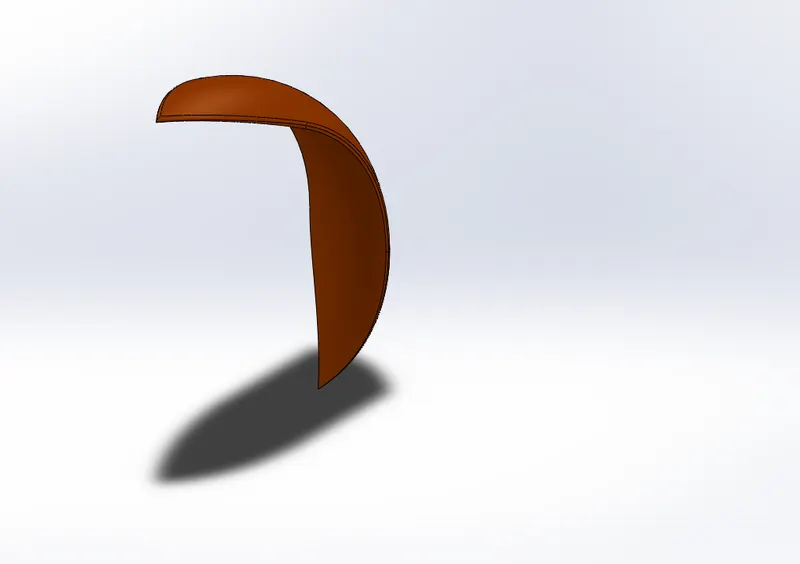
3.FRONT FENDER
The front fender is a part that frames a wheel well and it is used to prevent dirt from being thrown into air by the rotating tyre.
Commands used:
2d sketch
Revolve
Spline
Split
Fillet
Appearances
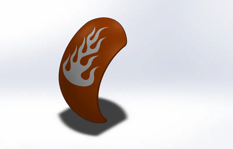
4. REAR FENDER
The rear fender does the same works as front fender
Commands used:
2d sketch
Revolve
Spline
Split
Fillet
Appearances
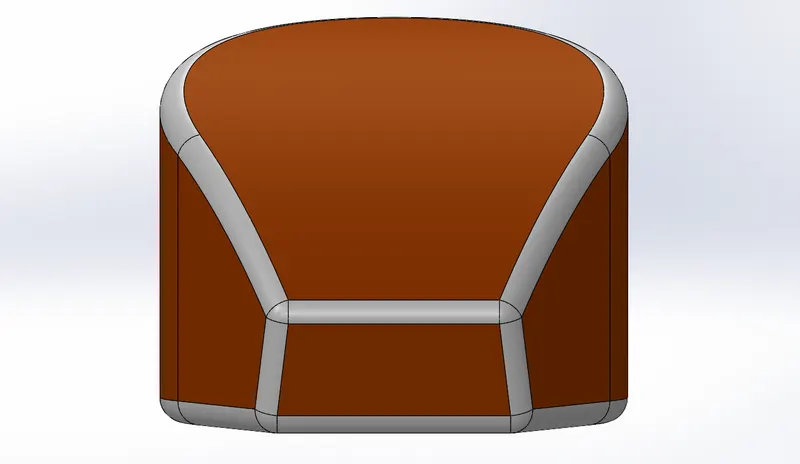
5.OIL TANK
The oil tank is a safe container for holding fuel and released into engine
Commands used:
2d sketch
spline
extrude
combine
fillet
shell
appearance
6. CHAIN
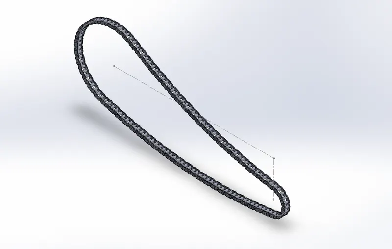
Chain is used to transmit power from the engine to wheel.
Commands used:
2d sketch
straight slot
extrude
fillet
curve pattern
mirror
body _delete/keep
appearances
7.PEDAL
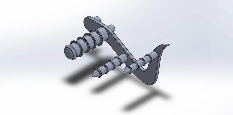
Used to rest a foot of rider
Commands used:
2d sktech
spline
revolve
dome
extrude
chamfer
linear pattern
fillet
appearance
8.FRONT-WHELL
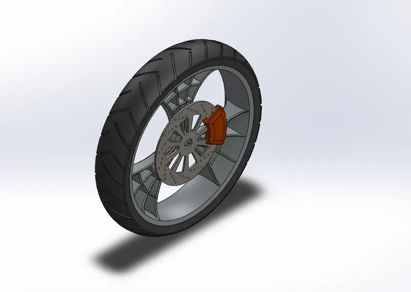
In this model commands used
commands used:
2d sketch
revolve
spline
extrude
cut-extrude
cut-revolve
circular pattern
combine
fillet
appearance
9.REAR-WHEEL
In this model commands used are
commands used:
2d sketch
revolve
spline
extrude
cut-extrude
cut-revolve
circular pattern
combine
fillet
appearance
10.FRONT FORK
The front fork connnects front wheel and axle to frame and it is used as handle of the bike.
commands used:
2d skech
spline
revolve
linear pattern
sweep
dome
project curve
plane creation
mirror
combine
extrude
fillet
appearance
body - move/copy
11.CHASIS
chasis is chopper core structure that is used to support the engine. At front of the chasis that holds the fork while at the rear is attached to the rear wheel.
commands used:
2d sketch
spline
project curve
sweep
dome
combine
revolve
cut-extrude
split
extrude
fillet
appearance
12.ENGINE
The engine powers the chopper.
commands used:
2d skech
spline
revolve
circular pattern
revolve
sweep
project curve
composite curve
dome
cut-extrude
split
extrude
fillet
chamfer
appearance
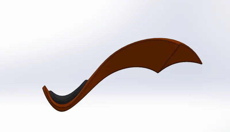
13.GAS TANK
The gas tank is a fuel reserviour to meet the fuel requirement of the vehicle.
commands used:
2d sketch
surface
sweep
surface trim
surface loft
project curve
boundary-surface
mirror
surface-knit
split line
surface - extrude
cut - sweep
fillet
shell
appearance
ASSEMBLY:
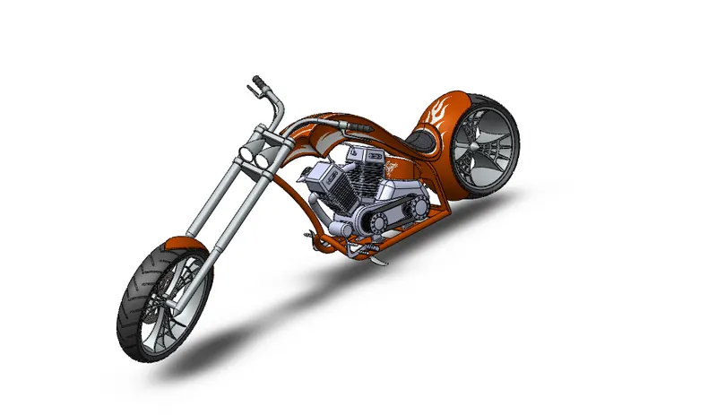
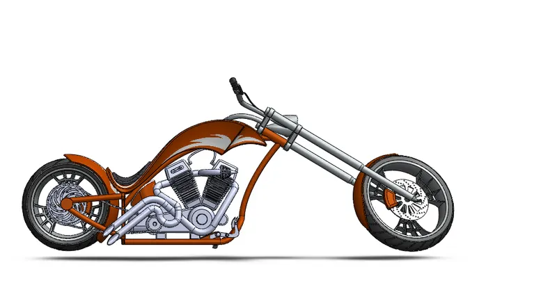
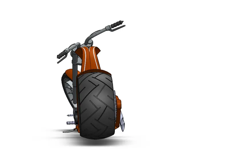
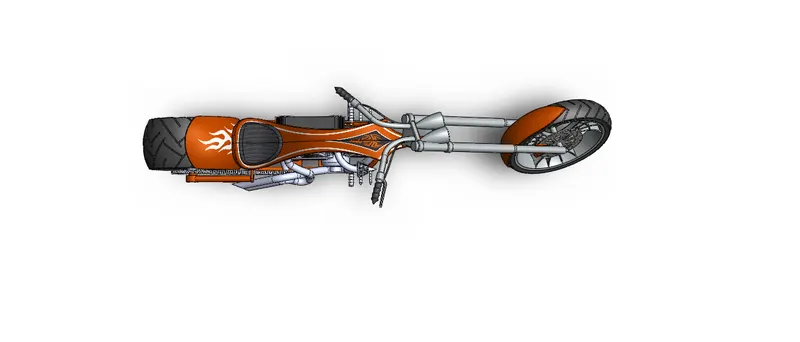
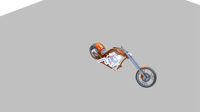
All the parts of the chopper are combined in the solidworks assembly environment and placed in their respective position with the help of the mates.
ISOMETRIC VIEW
SIDEVIEW
BACKVIEW
TOPVIEW
RENDERING:
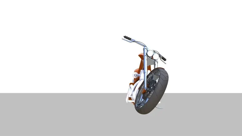
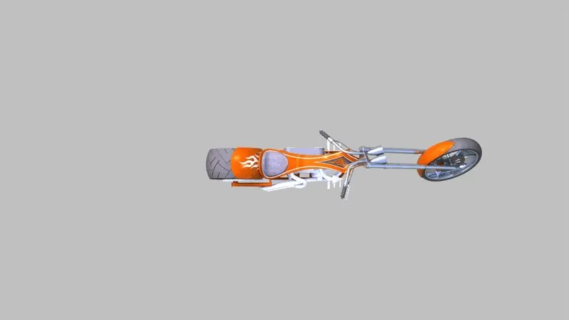
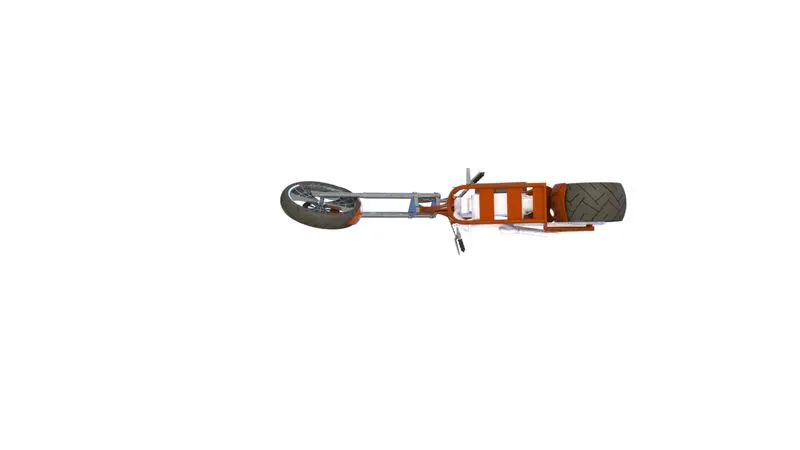
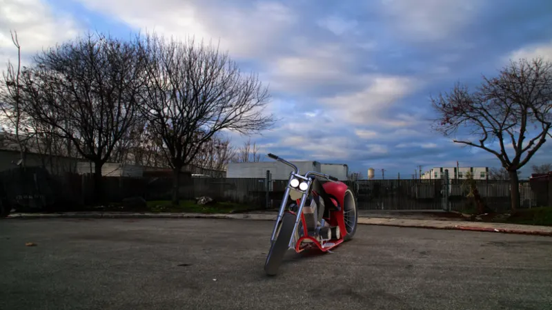
The rendering of the chopper in done in solidworks photoview360.
Photoview 360 is a solidworks add-in that produces photo realistic rendering of the model.
front view
top view
bottom view
isometric view
CONCLUSION:
Thus assembly and rendering of american chopper has been done.