Photo Realistic Rendering
Design, Assembly and Rendering of American chopper using SolidWorks and SolidWorks Visualise
Objective:
Design parts of an American chopper.
Assemble parts in solidworks assembly.
Render a high quality image using photoview 360 and SolidWorks Visualise.
Software Used:
SolidWorks 2020 Edition.
SolidWorks is a parametric modeling software used for making/Designing models in industries such as automobile, aerospace, etc. The software is parametric, which means the model can be altered or modified at any given time. The design of the model changes with the alterations made in the part while modeling.
Introduction:
Being a design fan I am interested in knowing the working and the design of any parts. By automobile fan I also mean various vehicles such as planes, Ships ,bikes etc. The most interested in bikes. I have liked bikes since childhood, and since I got to learn about this course I thought about designing a bike in SolidWorks.
Design methodology:
Tools and features used while designing:
Sketch: This allows us to create a sketch on a plane or a flat body.
Line: This allows to create lines
Circle: This allows to create circles
Rectangle: This allows us to create a rectangle.
3d Sketch: This allows us to create sketches without selecting a plane or a surface.
Extrude Bose: This is used for extrude material in linear direction.
Extrude Cut: This is used for making holes or cuts in the solid body in linear direction.
Swept Bose: This is used for flow material along with path..
make pierce: This is used to put a center of the sketch on the end of a curve or a line.
Plane: This feature allows us to create a geometric plane with reference to a surface or other plane.
Curve: This is used for making curves with reference to the lines and splines.
Filet: This is used for making the corner edges round.
Chamfer: This isn't used for making the flat surface at edges.
Trim: This feature allows to remove the unwanted sketch
Extend Entities: This feature allows us to extend a line
Convert Entities: This is used to convert a edge or a face into a sketch
Shell: This feature allows us to create hollow components.
Surface Features used:
Surface Loft: This feature is used for flow material between different entities
Surface Fill: This feature is used for filling an open surface.
Surface Boundary: This is used for making a surface using a different direction.
Surface Extrude: This is used to extrude a surface using a line.
Surface Trim: This is used for removing extra surfaces.
Knit Surfaces: This is used for joining two or more surfaces and joining them to form a solid body.
Parts modeled:
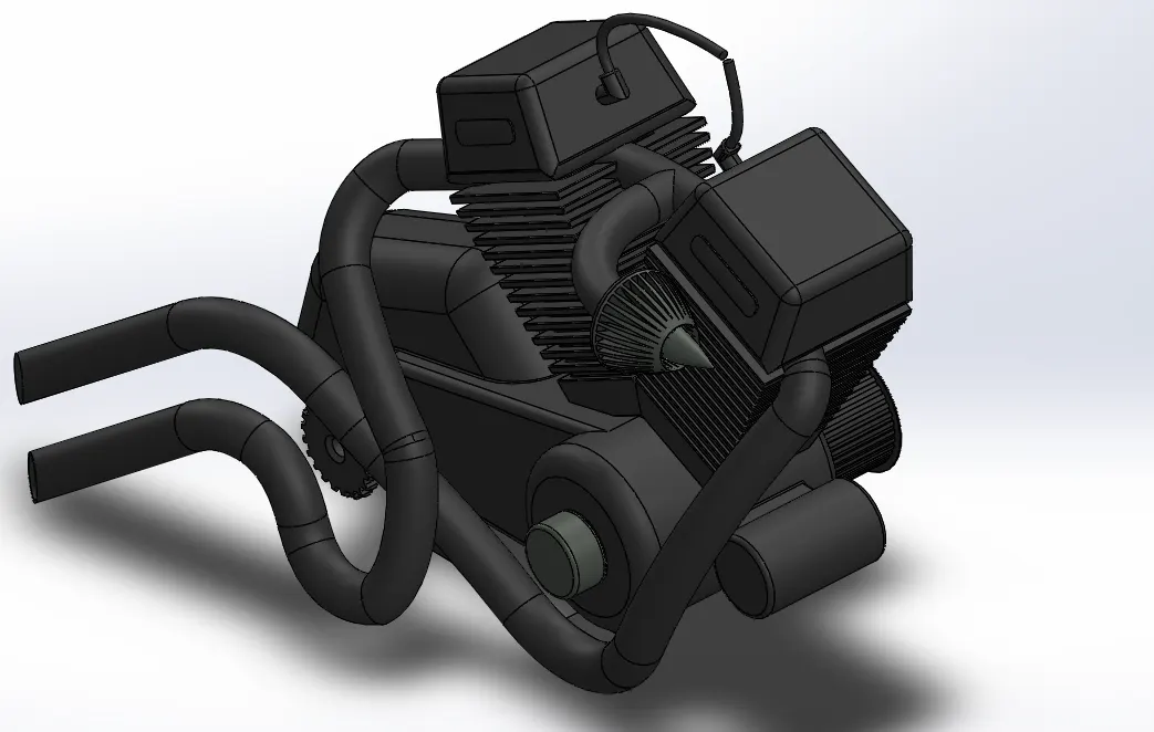
1. Engine:
This is the main part of the bike. It provides power to the bike.
Tools and Features Used:
Line
Spline
Circle
Shell
Projected Curves
Planes
Revolve
Surface Trim
Composite curve
3d Sketch
Extrude Cut
Extrude Bose
Part images:
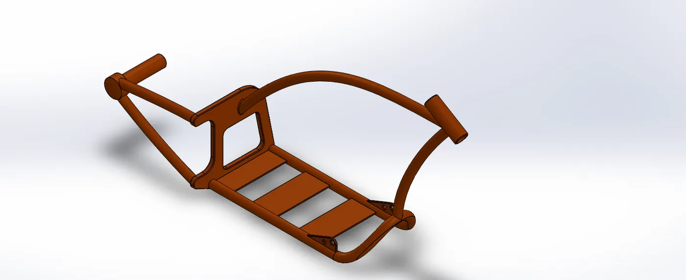
2. Chassis:
This is the base of the bike where all parts of the bike are mounted.
Tools and features used:
Lines
Extrude bose
Fillet
Circle
Plane
Part Images:
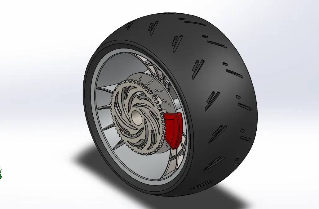
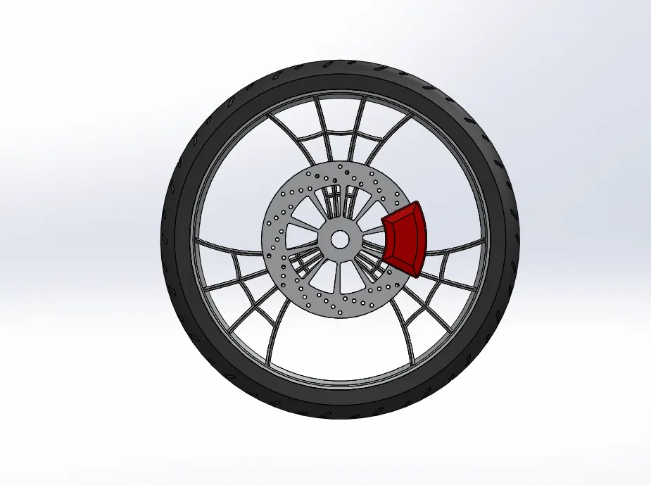
3.wheels:
This is the part which carries the load of the bike and provides smooth riding.
Tools and Features used:
Line
Extrude Cut
Extrude Bose
Revolve
Part Images:
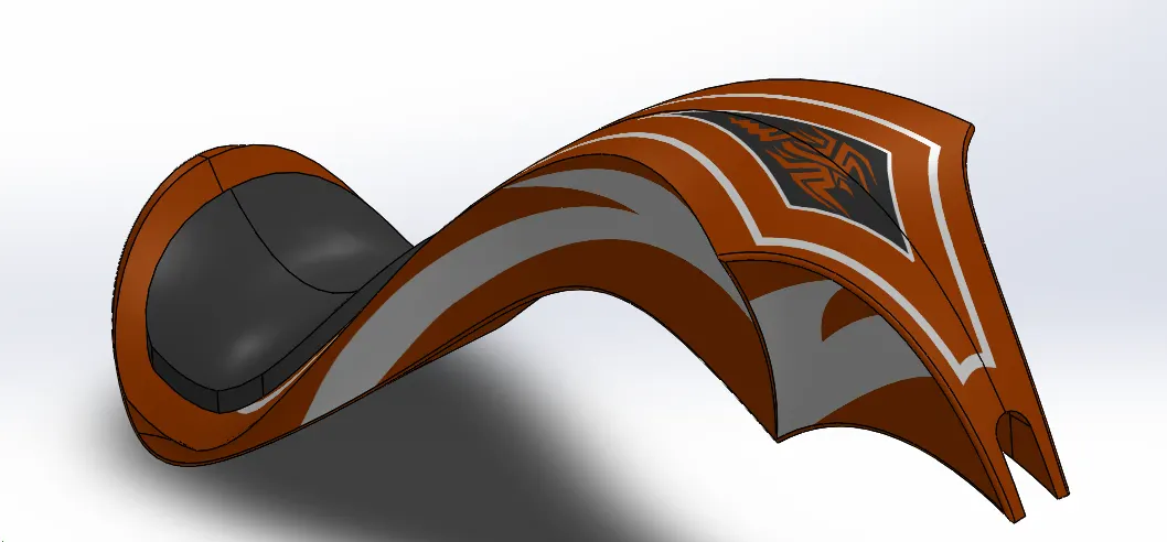
4.Gas Tank:
This is used for fuel storage.
Tools and features used:
line
mirror
Surface loft
combine
Part image:
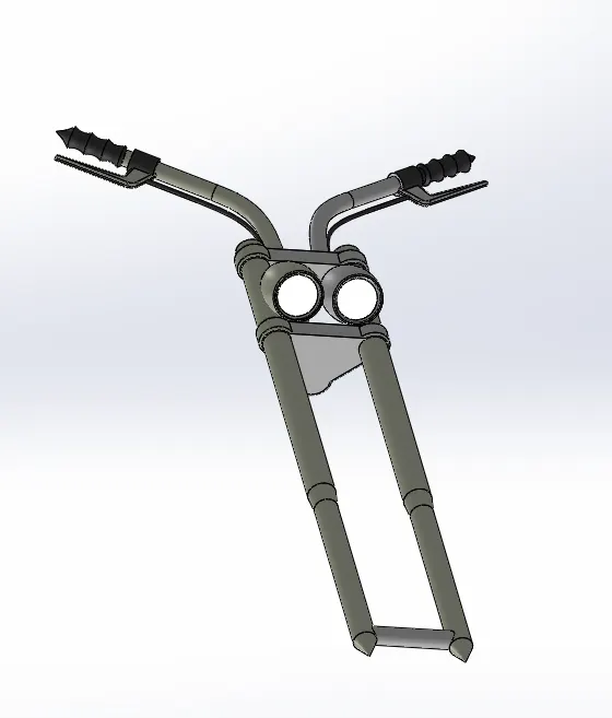
5. Fork
This is used to control the bike and provides the direction tp bike.
Tools and features used:
Lines
Extrude Cut
Extrude Bose
Circle
5. Revolve
6. Mirror
7. 3d sketch
Part Images:
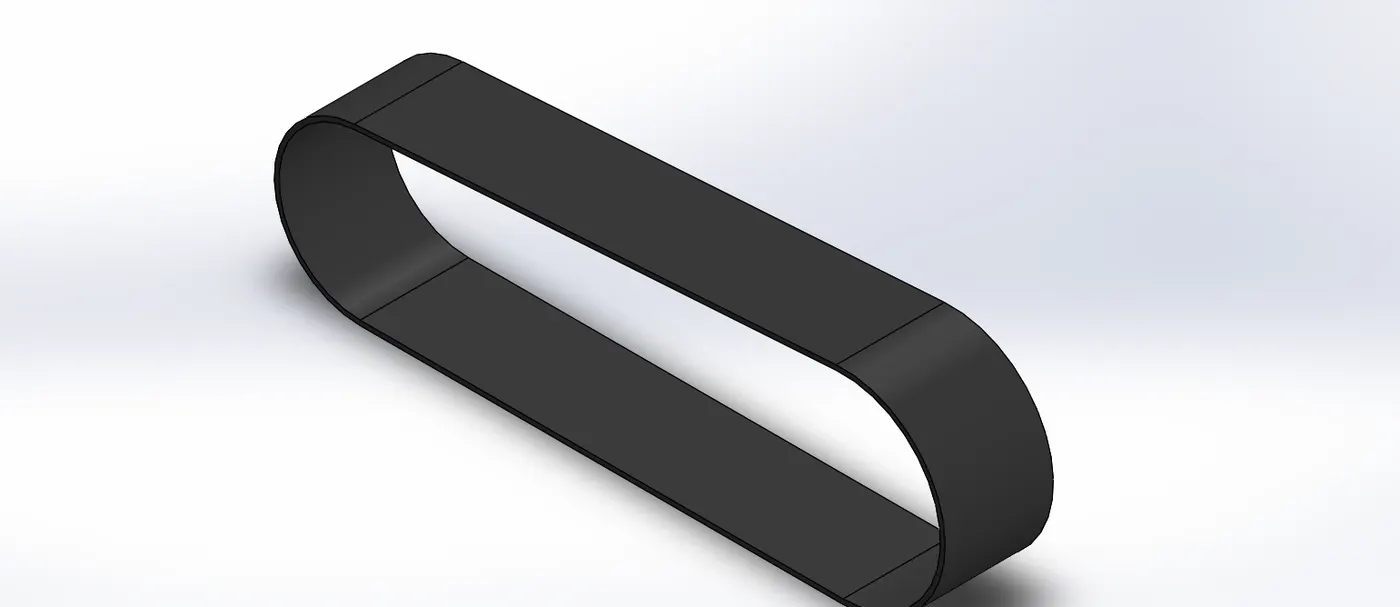
6. Transmission belt:
This is used to transmit power between the crankshafts and the component parts.
Tools and Features used:
Line
Extrude Bose
Part Images:
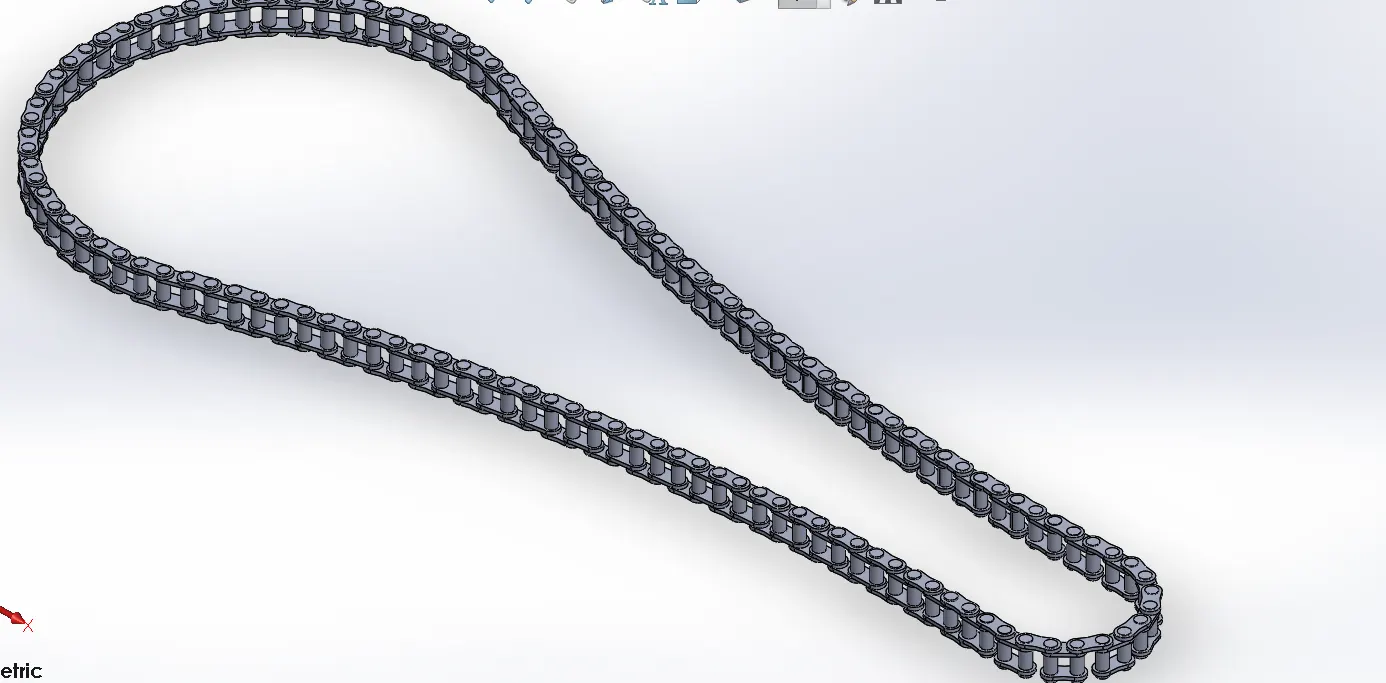
7. Transmission chain:
This is use to transmit power between the engine and rear wheel.
Tools and Features used:
Extrude boss
Curve driven pattern
mirror
Part image:
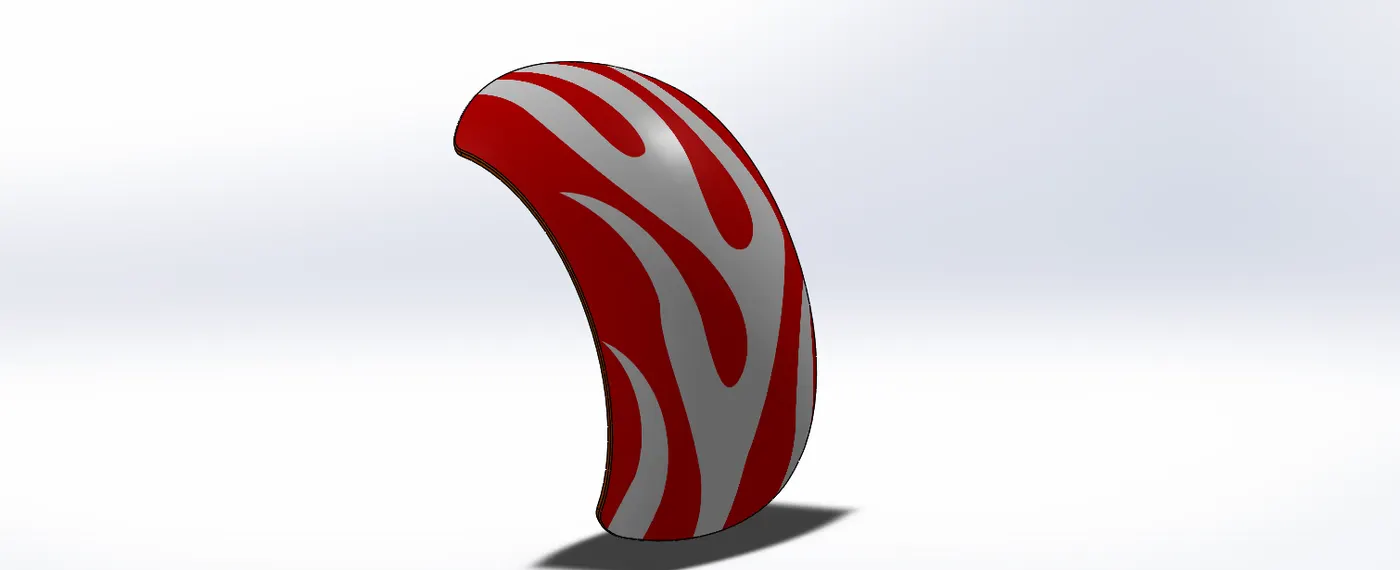
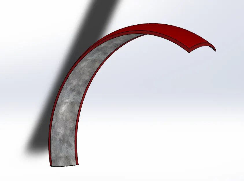
8. Fender
This part is used as a guard to cover wheels and protects from mud.
Tool and features used:
1. Spline
2. Revolve
Part image
Assembly of American chopper:
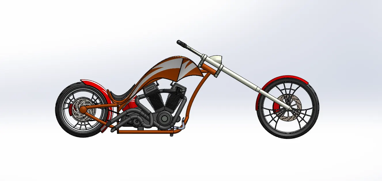
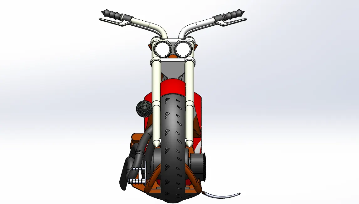
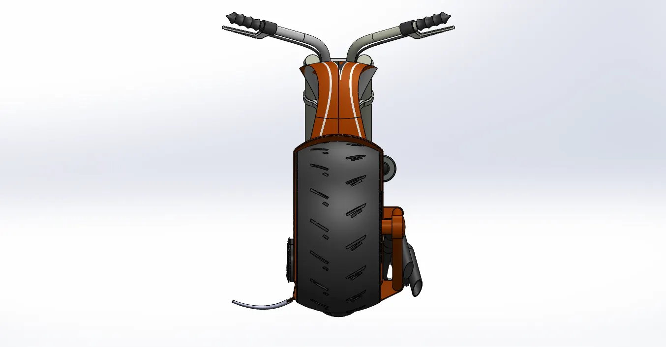
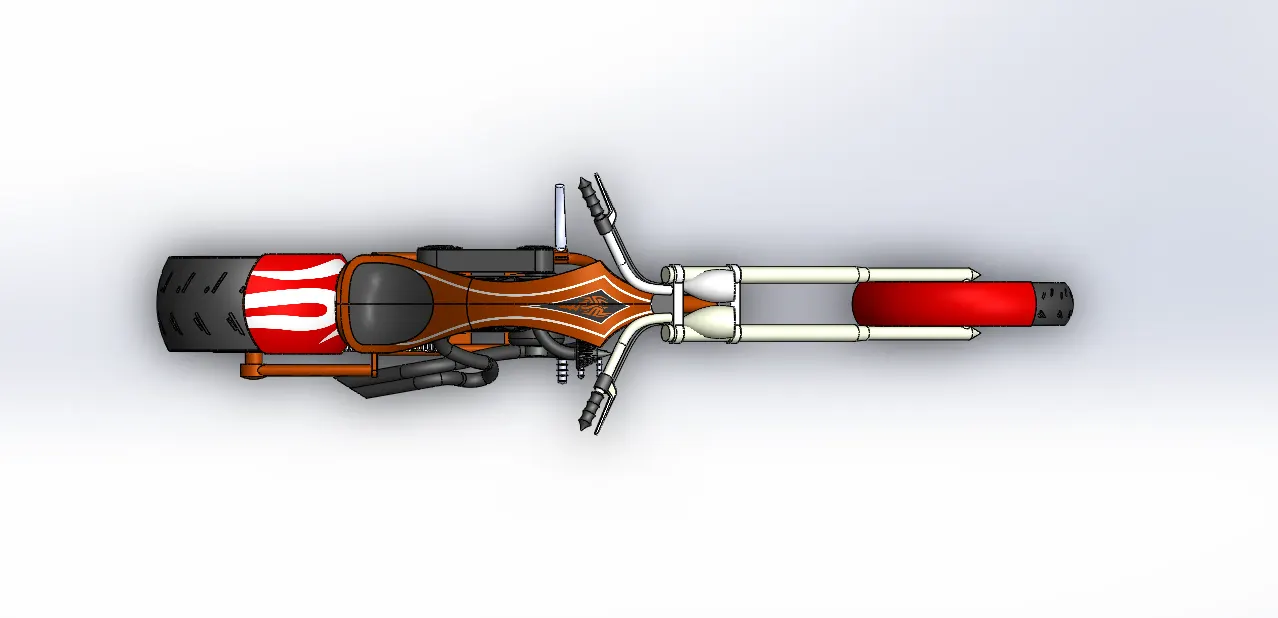
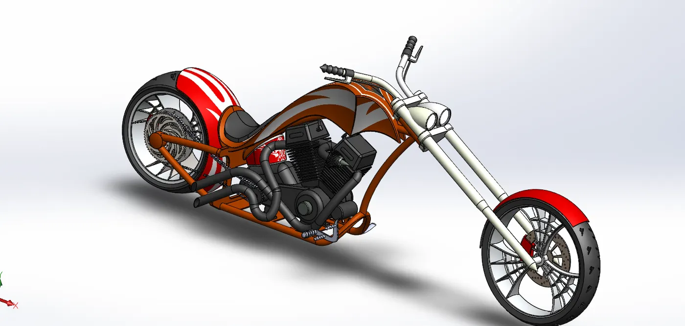
The bike is assembled in the solidworks assembly. Various mates are used to construct the bike
Mates Used:
Concentric
Width
Distance
Distance Limit
Angle Limit
Coincident
Parallel
Images of the Assembly:
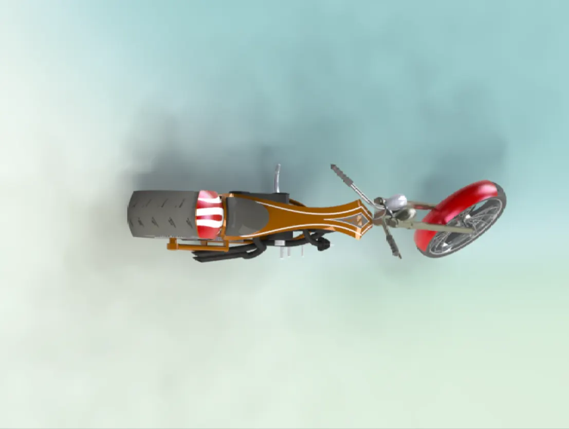
Rendering using PhotoView 360:
PhotoView 360 is rendering software which is used to convert digital models into realistic images and is available as an add - in the solidworks.
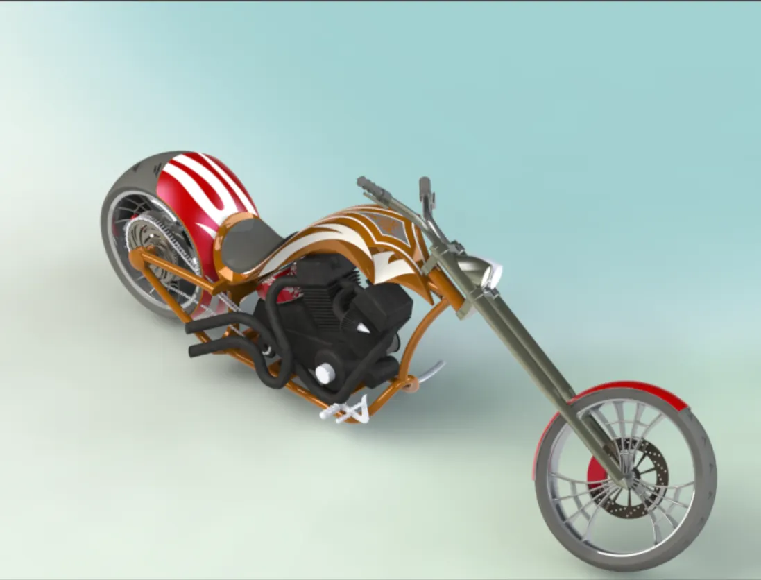
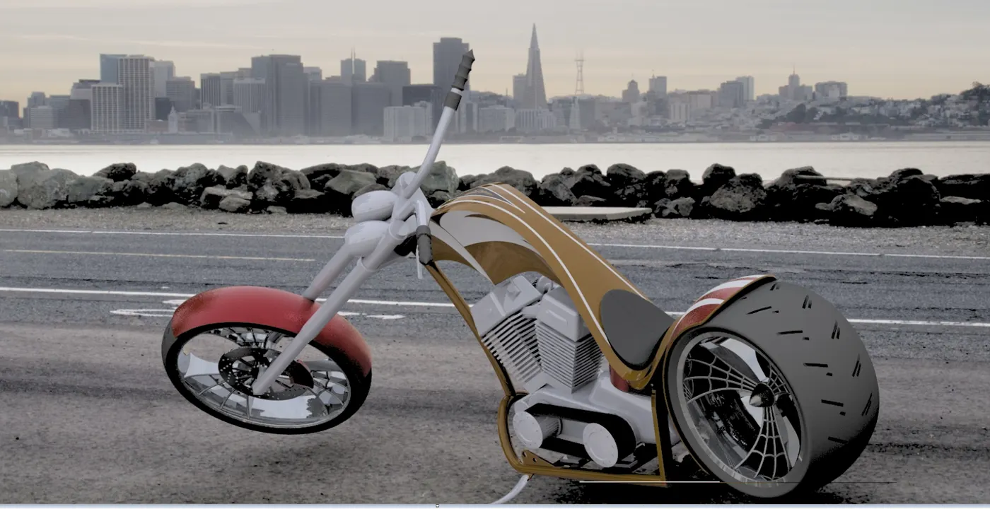
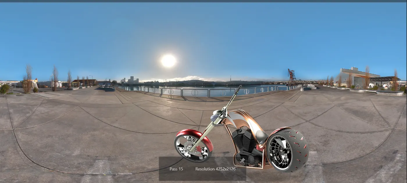
Rendering using SolidWorks Visualise
SolidWorks Visualise is an extensively high rendering tool.
Conclusion:
All the parts are designed in solidworks software.
The parts are assembled in the solidworks assembly
The assembled bike was rendered using Photoview 360 as well as SolidWorks Visualise.