Photo Realistic Rendering
Modelling And Assembly of American Chopper Using Solid works
Objective: To Model and assemble the different parts of bike (American Chopper) using solid works software.
Introduction: The main tool used to model the chopper was the solid works cad tool. It is a solid modelling software which uses the 2D sketch and made into a 3D solid object by using many tools and commands in the software. In this project I made different individual parts of bike and assembled together using varies tools and commands.
Parts of the American Chopper
- Transmission Belt
- Kickstand
- Front Fender
- Rear Fender
- Oil Tank
- Chain
- Pedal
- Front Wheel
- Rear Wheel
- Front Fork
- Chassis
- Engine
- Gas Tank
Transmission Belt
This model consists of diving and driven pulley towards the gear box and rear wheel respectively. It is used to transmit the power from engine to the wheel. The inner side of the transmitting belt has the grove like teeth to fix exactly with the mating parts.
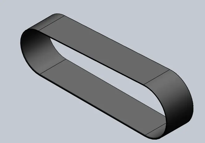
Types of features and commands used to model the Belt
- 2D Sketch as per dimensions
- Offset the required entities
- Extrude Boss/Base
- Fillet
Kickstand
It is a metal part attached to the chassis at the bottom of the bike. It is used when bike is in rest and helps to stand on ground without falling. Stand will be set in horizontal while bike is in motion and can be pull down to use.
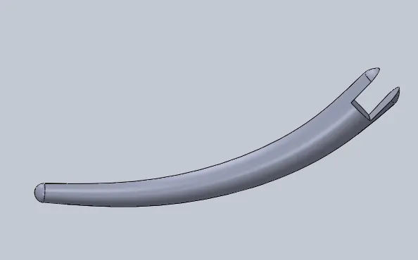
Feature tree
- 2D sketch
- Extrude Boss/Base
- Extrude cut
- Lofting
- Dome
- Fillet
Front Fender
A fender is essentially a covering for your bike tires that protects you from the rain. Riding with fenders will prevent the rain from splashing a streak of muddy water up your back, over your shoes and on your face. It is also called as Mudguard.
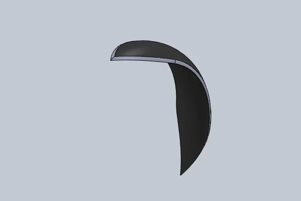
Types of features and commands used to model the Fender
- 2D sketch
- Revolved surface
- Surface Trim
- Thicken
- Extrude cut
- Fillet
Rear Fender
Rear fender does the same operation as the front fender for the rear wheel.
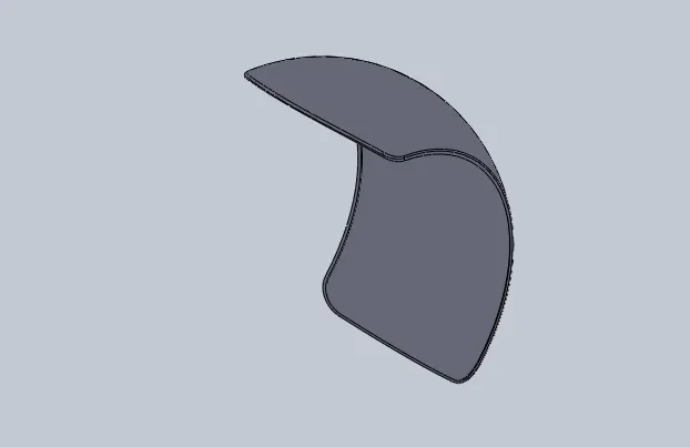
Features used
- 2D sketch
- Revolved surface
- Surface trim
- Thicken
- Extrude cut
- Fillet
- Shell
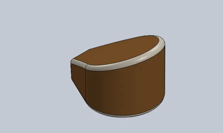
Oil Tank
A motorcycle oil tank is a tank that holds the capacity of oil used to cool the motorcycle. Motorcycles that use oil to keep the engine cool have an oil tank allowing for excess oil to circulate through the engine and through an oil cooler mounted to the front of the motorcycle.
Features used
- 2D sketch
- Surface Extrude
- Fillet
- Surface trim
- Surface knit
- Shell
- Extrude
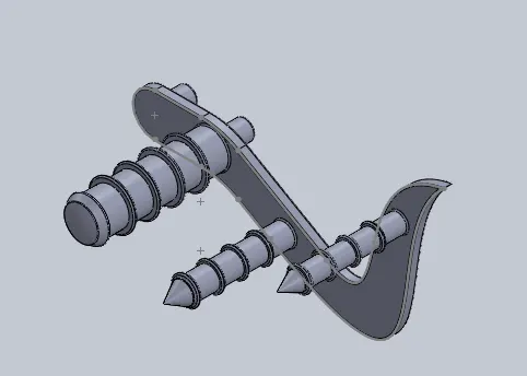
Pedal
Pedal is the part of the chopper motorcycle attached to chassis; the driver can rest his foot on the pedal while driving.
Features used
- 2D sketch
- Loft
- Fillets
- Cut extrude
- Extrude boss
- Split
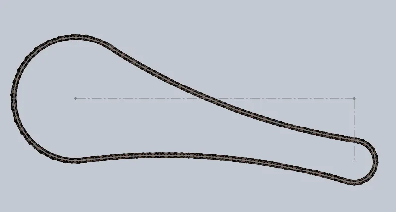
Chain
On many motorcycles, the chain connects the output shaft of the transmission to the rear wheel. It makes the rear wheel turn, which moves the motorcycle.
Circular pattern: This comm allows you to create copies of objects arranged in a pattern both easier and faster.
Features
- 2D sketch
- Extrude
- Mirror
- Fillet
- Curve driven pattern
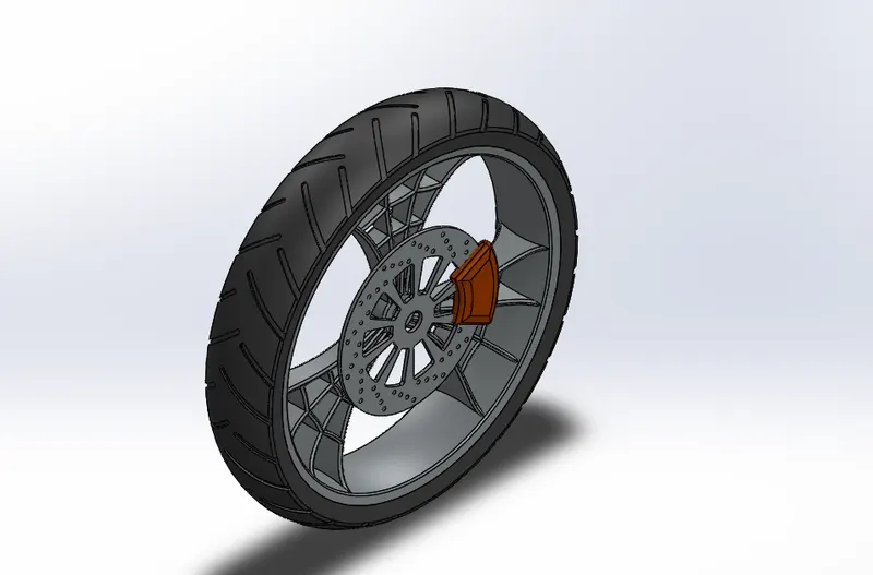
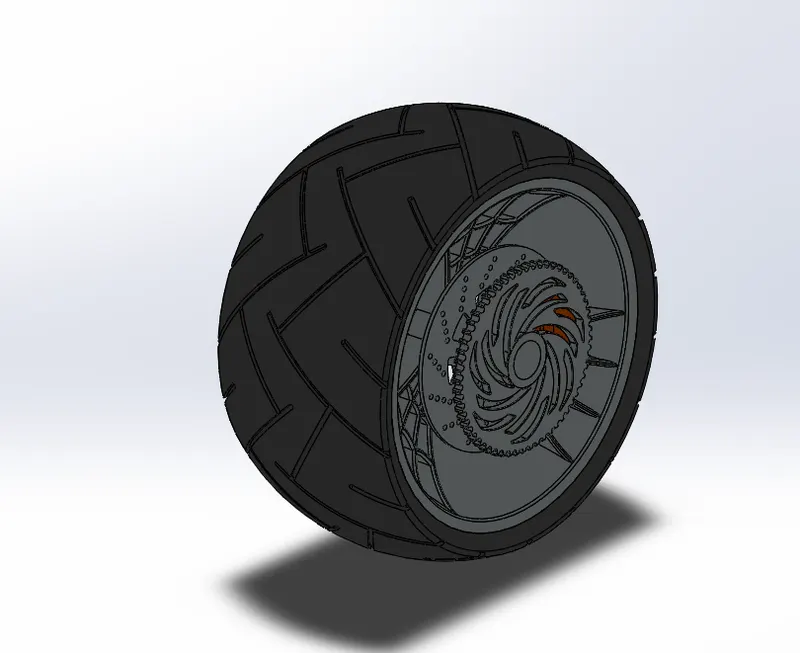
Front wheel and Rear wheel
Motorcycle wheels are made to cope with radial and axial forces. They also provide a way of mounting other critical components such as the brakes, final drive, and suspension. Wheels and anything directly connected to them are considered to be unsprang mass.
The wheels consist of wheel rims, disc brake rotors and callipers etc…
Features used
- 2D sketch
- Extrude
- Extruded cut
- Thin extrude
- Revolve
- Revolved cut
- Fillet
- Chamfer
- Linear pattern
- Mirror
- Circular pattern
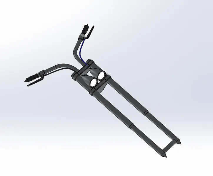
Front fork
Front fork is the part of the bike that holds the front wheel. A fork typically consists of two blades which are joined at the top by the fork crown. The crown is often at the front. Most suspension forks have an arch connecting the two side of the lowers (the part connected to the axle).
Features used
- 2D sketch
- Extrude
- Revolve
- Fillet
- Sweep
- Shell
- Mirror
- Dome
- Linear pattern
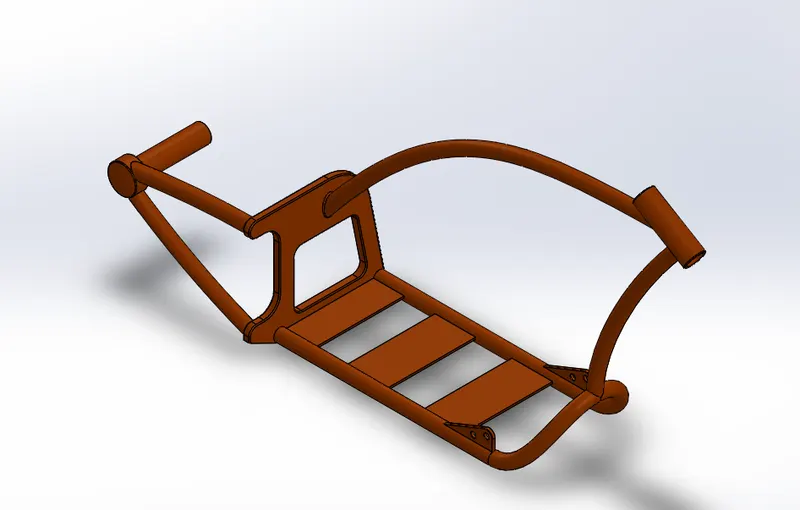
Chassis
A chassis serves as a motorcycle frame made of steel, aluminium or an alloy. The frame consists mostly of hollow tubes and serves as a skeleton on which components like gearbox and engine are mounted. The frame also keeps the wheels in line to maintain the handling of the motorcycle.
Features used
- Blueprint
- Extrude boss
- Fillets
- Revolve
- Circular pattern
- Dome
- Extrude cut
- Chamfer
- Mirror
- Project curve
- Split
- Sweep
- Combine
- Composite curve
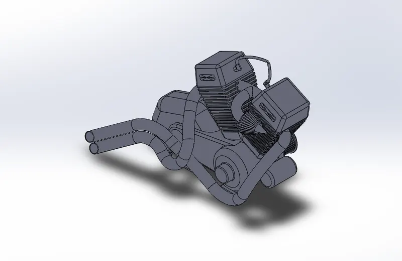
Engine
Engine is like heart to the bike which produces the power. It consists of pistons, a cylinder block and a head, which contains the valve train. The pistons move up and down in the cylinder block, driven by explosions of a fuel-air mixture that has been ignited by a spark.
Features used
- 2D sketch
- Extrude
- Extrude cut
- Thin extrude
- Chamfer
- Projected curve
- Linear pattern
- Circular pattern
- Fillet
- Mirror
- Dome
- Sweep
Gas tank
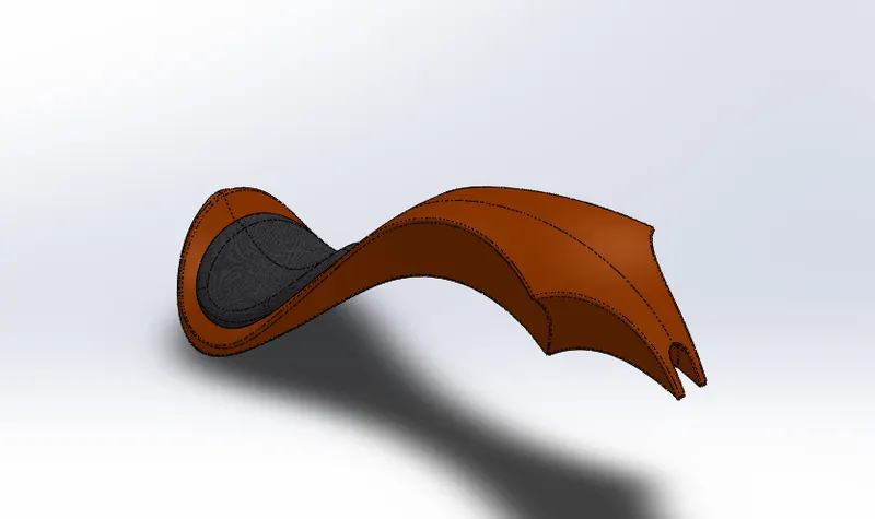
A gas tank is also known as fuel tank or a petrol tank in bike which is a safe container for flammable fluids. Though any storage tank for fuel may be so called, the term is typically applied to part of an engine system in which the fuel is stored and propelled or released into the engine.
Features used
- 2D sketch
- Surface loft
- Split line
- Face delete
- Projected curve
- Fillet
- Mirror
- Extrude cut
- Knit surface
- Thicken
- Shell
Assembly of American chopper
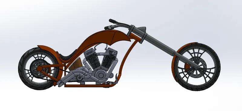
After modelling all the chopper parts individually assembled together as a complete chopper. You can build complex assemblies consisting of many components, which can be parts or other assemblies called subassemblies. For most operations, the behaviour of components is the same for both types. Adding a component to an assembly creates a link between the assembly and the component. When solid works opens the assembly, it finds the component file to show it in the assembly. Changes in the component are automatically reflected in the assembly.
Features used
- Mate/coincident
- Parallel mate
- Distance mate
- Concentric mate
- Mirror components
Rendering
Rendering in solid works is a stage where the final model is modified externally to make it more realistic and attractive using solid works visualize. We get access to different kinds of environments with different backgrounds which enables us to place our models in it and view to get a better idea of how our model might look in the real world.
Solid works visualize will help us to set different colour tones to our models, add different materials, adding shadows, adding lights and many more good features.
I used solid works visualize to a good extent in order to view the American chopper model in a realistic environment and also by adding realistic materials, colours and shadow features to it.