Photo Realistic Rendering
MODELING OF AMERICAN CHOPPER ON SOLIDWORKS
OBJECTIVE
- To design an American chopper using Solidworks Solidworks
- To learn basic commands of Solidworks
- To create all parts of American chopper and assemble them
- To do rendering
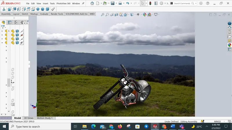
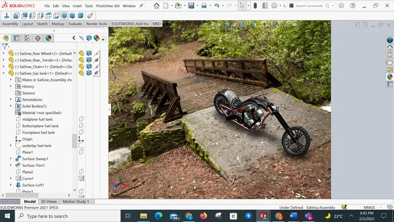
- Getting realistic with the help of photo view 360
INTRODUCTION
During this course, I learned how to design an American chopper assembly using Solidworks software. Initially, I learned about commands of Solidworks and started using them while designing American chopper. After completing the design of all parts I have done assembly of the chopper. After assembly, I have done rendering using photo view 360.
The following parts are designed during this course
1) Chasis
2) Engine with exhaust system
3) Front-wheel
4) Rear Wheel
5) Front fork
6) Front and rear fender
7) Oil tank
8) Chain
9) transmission belt
10) Kickstand
11) foot pedal
Design approach
STEP 1
Get to know about the Commands and Features of Solidworks.
Step 2
Started Designing each and every part of American chopper
Completed design of every part.
Step 3
Assembled all parts to get final Bike
Step 4
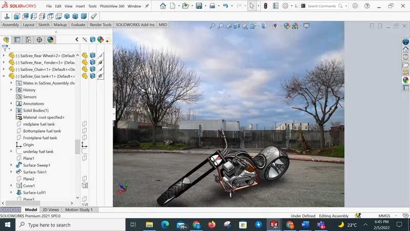
Rendering was done after assembly
Photo View 360 is used to get a realistic view
A small flow chart of the approach
Transmission Belt - ENGINE -Chain, Rear Wheel, Rear Fender
|
pedal, Gas tank
|
Front Fender
Description of features and commands used while designing parts
Extrude Boss: It is used to convert a 2D sketch into a Solid body. It can create a completely solid body of any shape with closed entities. In this feature, we can select the dimensions also.
Fillet: To avoid sharpness at the edges this feature is used. To give Roundness to the sharp edges we add fillets. Fillets not only to hides the sharpness of the solid body but also gives a good appearance to the body.
Revolve boss feature: This feature works around an axis, by selecting the axis of a sketch adds a round material by revolving around that axis. if there is no axis we can select an edge of a sketch and it gives us appropriate geometry.
Shell: This command gives some Idea about the inside appearance of a part. To make the body hollow this tool is used.
Linear patterns: This tool helps to create a single sketch that can be used multiple times. This feature is spaced uniformly along one or 2 linear paths.
Mirror: It creates a copy of solid parts. Apply feature to one or more multibody parts by selecting geometry patterns and using feature scope to choose which body should include the feature.
Projected Curve: This command is used to project a sketch into a 3D curve. By using this command we can create multiple projected curves from a single sketch. It does not create a curve of intersecting curves
Knit Surfaces: This is used to combine 2 or more faces and surfaces into one.
Mate: It is used to connect 2 components. Mate creates geometric relation between assembly and component. When we use the mate tool it defines the allowable motion of the component within its degree of freedom. The following are the mate features
1) Coincident mate 2) Concentric mate 3) Tangent 4) Angular mate
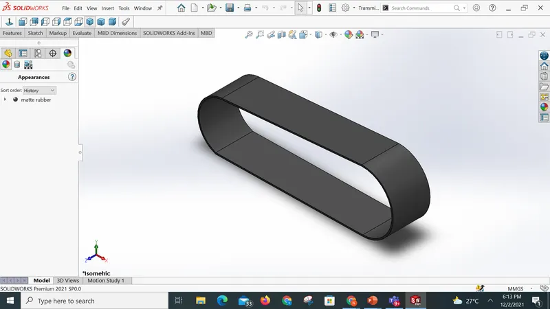
Transmission Belt :
The transmission belt is located at the round surfaces of the pulley to transmit the power with the help of pulleys.
The features used while creating the Transmission belt are as follows
Sketch
Extrude
Offset
Fillet
Appearance
Isometric view :
Front Fender :
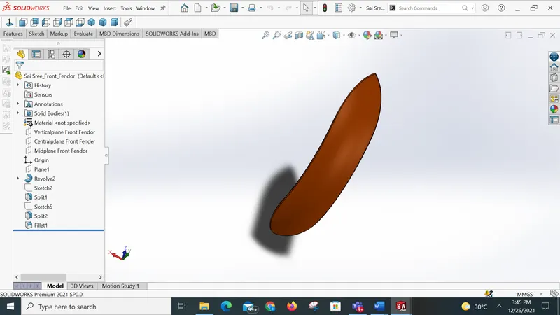
Features used to create front Fender
Sketch
3-Point arc
Offset
Extend
Trim
Revolve
Spline
Fillet
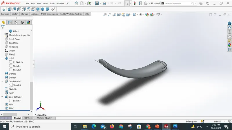
Kick Stand :
The kick Stand is placed in the middle of the Bike. Which is used to balance the bike when the bike is at rest.
Features used
Sketch
Ellipse
splines
Loft
Cut extrude
Boss extrude
Split
Isometric view
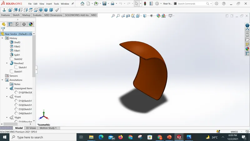
Rear Fender :
It is a part that frames a wheel well. used to protect the wheel
Features used :
Sketch
3-point arc
Extend
Trim
Revolve
Spline
Fillet
Shell
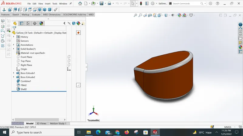
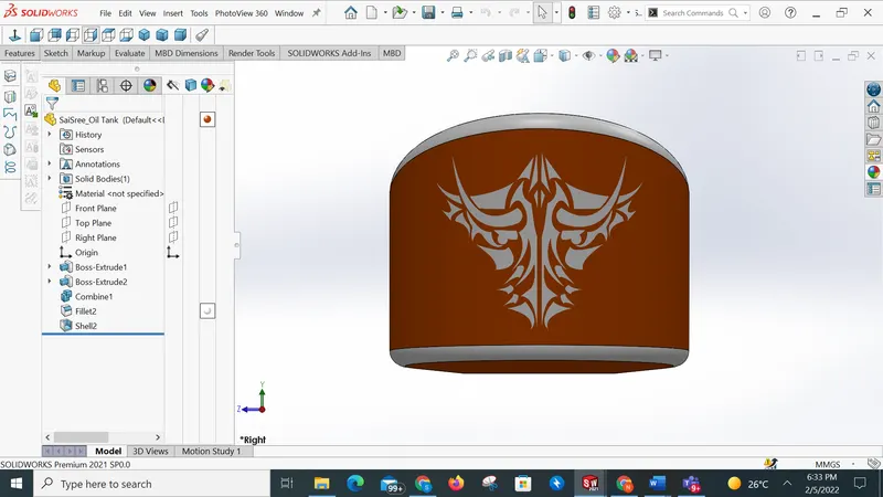
Oil tank
An oil tank is used to store oil.
Features used are
Lines
3-point arc
Boss extrude
combine
Fillet
Shell
Chain
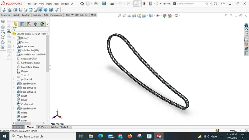
Chain in the Bikes are used to transmit power or energy from the engine to RearWheel
Features used while designing is as follows
Sketch
Circles
Slot
Block
Fillet
Curve pattern
Mirror
Pedal :
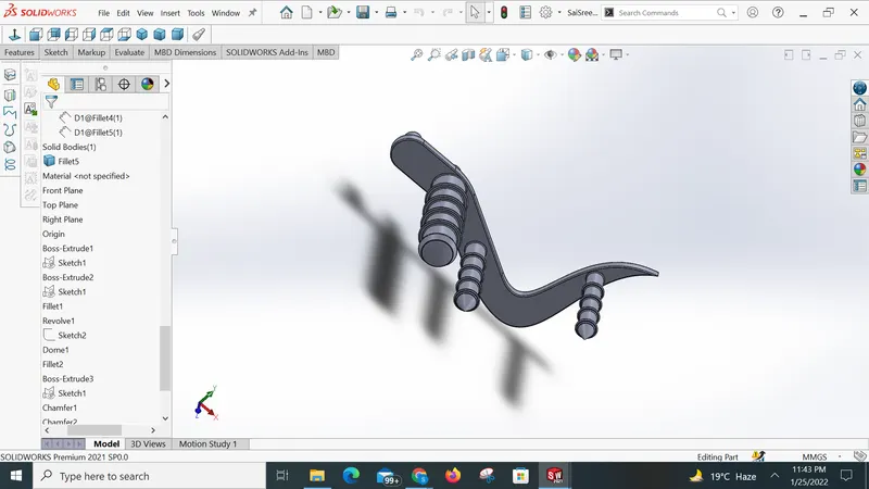
A pedal is a strong rigid body used to rest the foot while riding a bike. The following features are used to create chain
Sketch
Lines
Circles
Fillet
Revolve
Dome
Chamfer
Linear pattern
Front Wheel
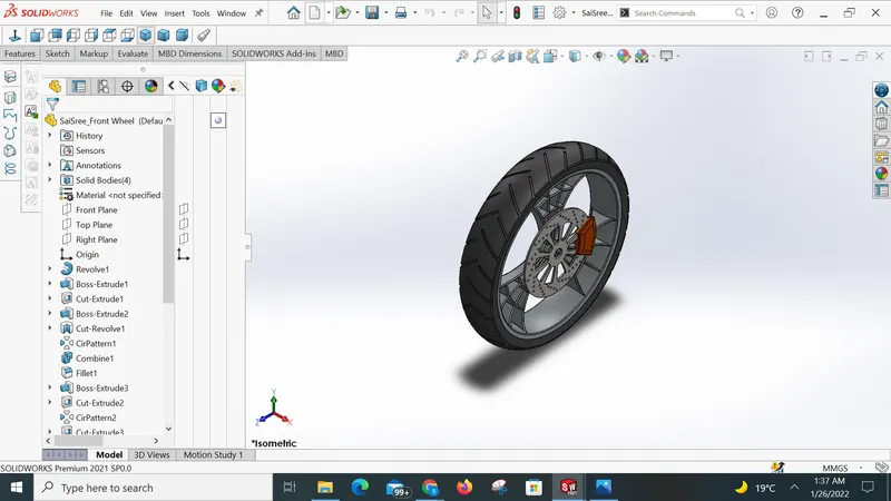
Front-wheel is located at the front portion of the bike. Front-wheel experiences greater force during breaking so, its diameter is more than the rear wheel.
The features used while creating the front wheel are as follows
Sketch
Lines
3 point arc
Sketch fillet
Revolve
Spline
Extended
Cut extrude
offset
fillet
chamfer
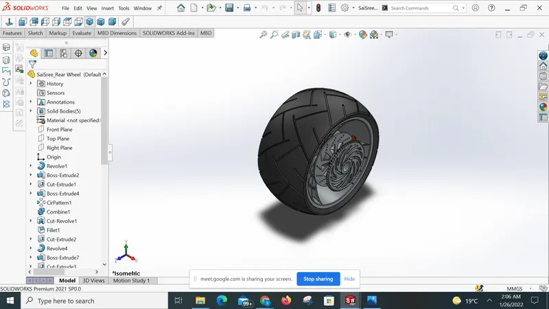
Rear Wheel
The rear wheel is used for accelerating the vehicle. The rear-wheel width is wider than the front wheel.
The features used to create Rear-wheel are as follows
Sketch
Lines
3-point arc
Sketch fillet
Revolve
Spline
Extend
Trim
Extrude cut
Offset
Revolve cut
circular patterns
Chamfer
fillet
Front Fork
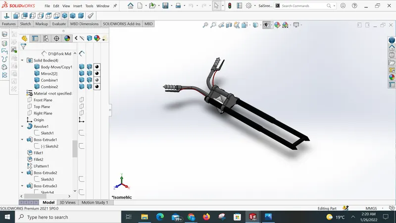
The front fork holds the front wheel and allows the front wheel to rotate. It gives suspension to the bike .
features used while creating the Front fork are as follows
Sketch
Lines
Revolve
Circle
Fillets
Linear pattern
Spline
Sweep
Extrude cut
Mirror
Combine
Chasis
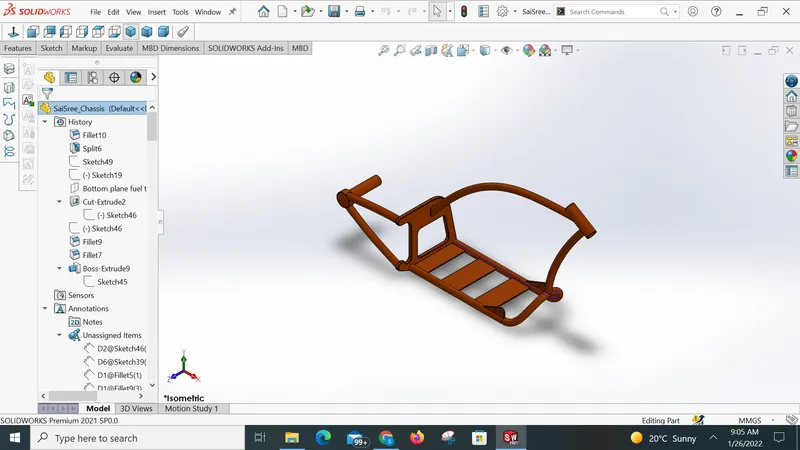
Chasis is a support to all the bikes and components. It is the mainframe of the chopper.
Features used to create the chassis are as follows
Blueprint sketch
Splines
Curves
Mirror
Boss extrude
Revolve
Combine
split
Engine
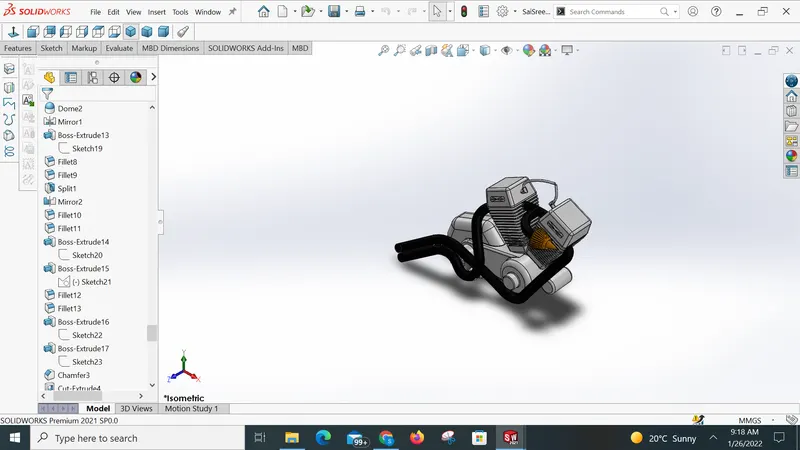
The important part of the bike is the engine. It supplies power to the bike .
Features used to create the engine are as follows
Sketch
Blueprint Sketch
Boss extrude
Revolve
Combine
Mirror
Cut extrude
Composite curve
split
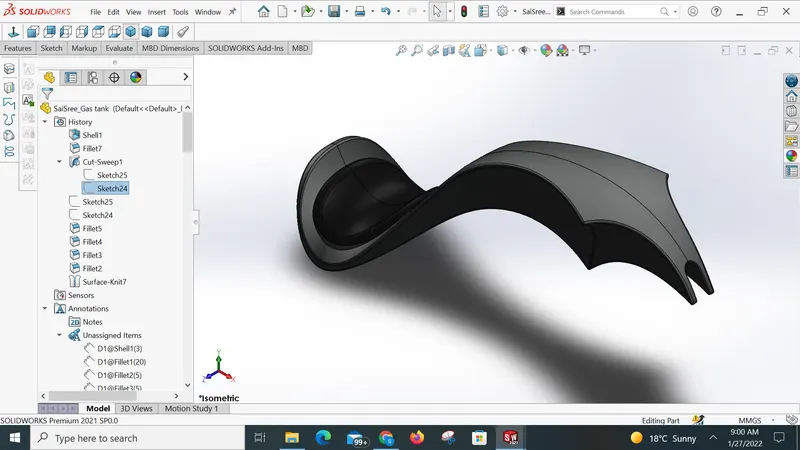
Gas tank
A gas tank is a container used to hold the fuel supply in the vehicle.
Features used to create the gas tank
Blueprint sketch
Spline
Surface sweep
Surface trim
Surface boundary
Surface loft
Curve
Surface knit
Surface extrudes
Fillet
Extrude cut
Shell
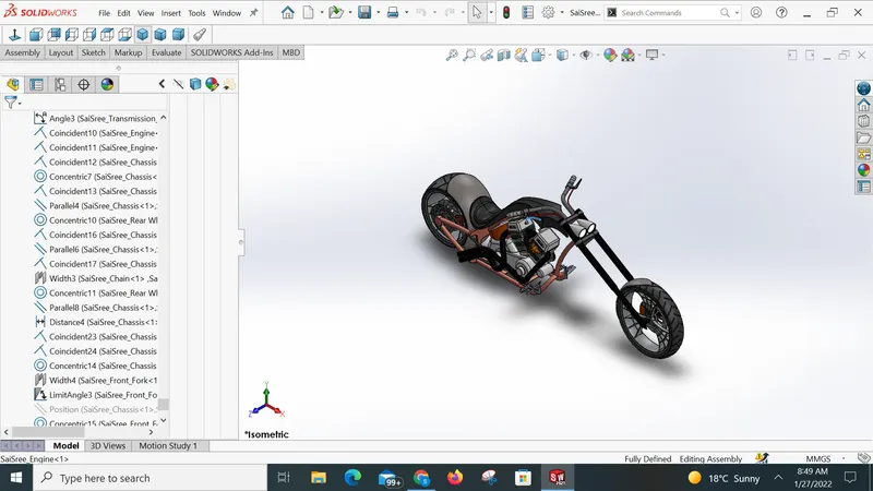
Assembly of the chopper :
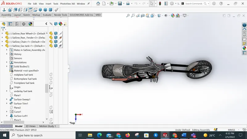
After designing all parts, the parts are assembled to create a complete Bike. During the assembly, the Mate feature is mostly used to connect the components.Few parts are modified to make it perfect according to requirements.
Decals :
In this portion, I attached stickers to the bike. Stickers are placed on the Rear fender, oil tank, and Gas tank. This gives a nice appearance to the chopper.
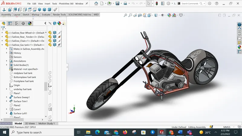
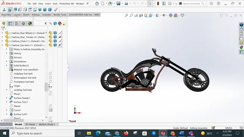
Rendering
Conclusion
During this course, I learned about the features of Solidworks. It was great learning. Gained so much knowledge on Solidworks.