Photo Realistic Rendering
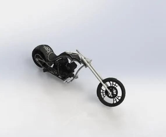
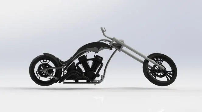
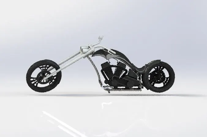
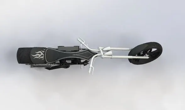
American Chopper
Objective:-
The objective is to perform all the parts and assembly in a correct and appropriate manner to complete the American Chopper Assembly with efficiency using Solid Works.
Introduction:-
- The American Chopper is a two-wheeled motorcycle that has been designed using the software Solid Works. The parts that are to be designed in order to perform the entire American Chopper should be given appropriate dimensions and proper placement of the product.
- The American Chopper has the following parts involved in it. The corresponding parts are:-
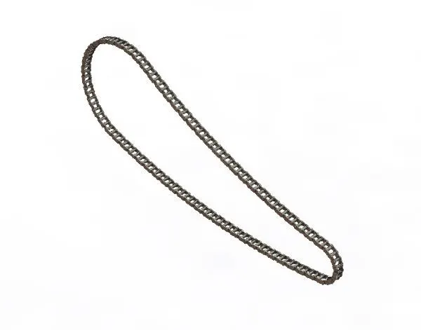
- Chain
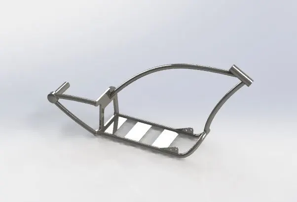
- Chassis
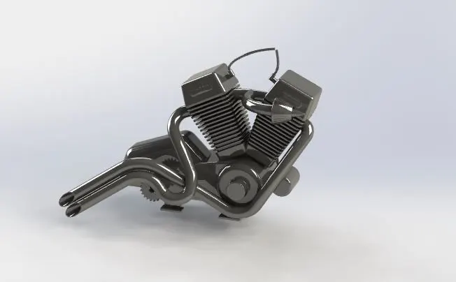
- Engine
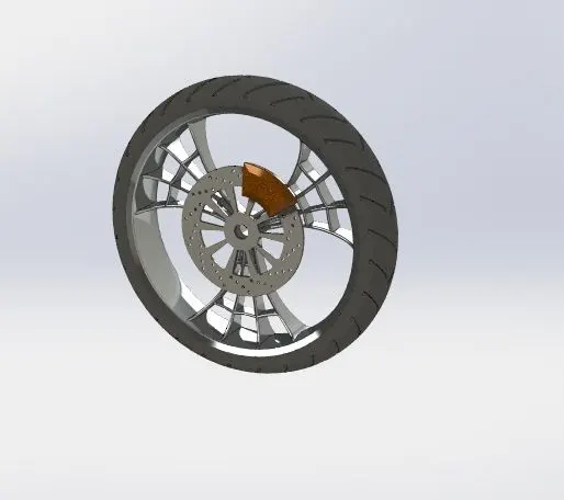
- Front Wheel
- Front Fender
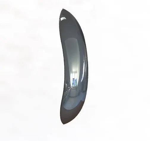
- Front Fork
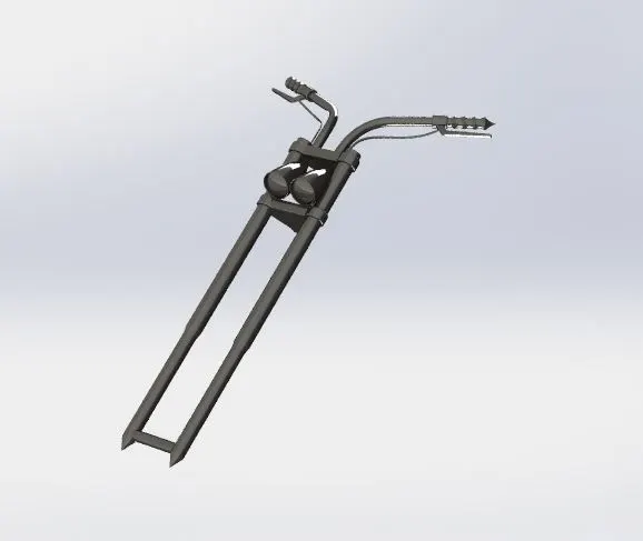
- Gas Tank
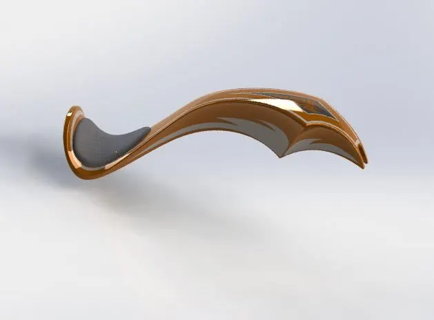
- Kick Stand
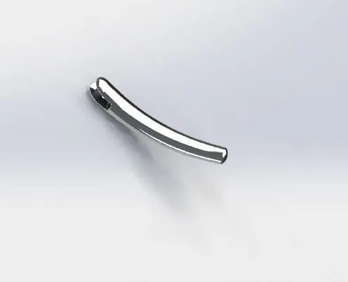
- Oil Tank
- Pedal
- Rear Wheel
- Rear Fender
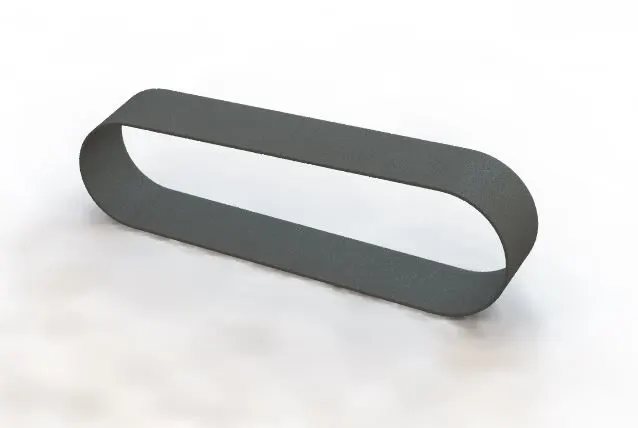
- Transmission Belt
Design Methodology/Approach:-
The following approach and design methodology has been used for the completion of the American Chopper:
- The part designing of all the parts of the American Chopper using various drafting tools has been utilized for performing the design of American Chopper.
- Once the part designing is completed then the American Chopper is completed by combing all the designed products, i.e, by the assembly of the products that are designed.
- Once the Assembly is completed, then the decals have been added to the American Chopper to elevate the look of the motorcycle.
Description:-
At the start of the Assembly Chopper, one should select the following plane that they want to perform the pert design. The software consists of the following planes:-
- Front Plane:- The main perspective of this plain is from the front point of view.
- Top Plane:- The main perspective of this plain is from the Top point of view.
- Right Plane:- The main perspective of this plain is from the right point of view.
The tools that have been utilized in the Solid Works for the completion of American Chopper are mentioned below:-
Once we select the plane in which we want to perform our drawings or our designs then we shall sketch the product that we want to design. The sketch has the following features in it:-
- Geometric Features:-
- We can draw different shapes by using the sketch feature, like lines, circles, etc.
- Smart Dimension:-
- Then we can give the corresponding dimensions for the sketch that we want to perform using the smart dimension feature.
- Trim Entities:-
- The trim entities feature is used to cut any extra lines from the sketch that has been performed.
- Convert Entities:-
- The convert entities are used to convert the sketch that is performed hand we can use the converted entity two perform future sketches also.
- Offset Entities:-
- This is a very handy tool to offset any sketch which can be both inside or outside.
- Offset On Surface:-
- The Offset on Surface is a very handy tool that is used to offset any entity on a surface.
- Mirror Entities:-
- It is used to mirror any entity or sketch exactly by using any plan as a reference.
- Sketch Patterns:-
- The sketch pattern basically has two types of sketch patterns that are a linear sketch pattern and a circular sketch pattern.
- Split:-
- The split feature is used to split any feature into two or more by using a thin line.
Features:-
Extruded Boss/Base:-
The extruded boss base is used to convert any 2D sketch into a solid 3D body on a plane.
Revolved Boss/Base:-
The revolved boss base is used to convert any 2D sketch to a 3D sketch that is a 3D solid body by revolving around the corresponding sketch.
Swept Boss/Base:-
The swept boss base is used to convert any 2D sketch into a solid 3D body in which the sketch is shaped as a swept.
Lofted Boss/Base:-
The lofted boss base feature is used to loft any base of a solid body.
Extruded Cut:-
The extruded cut is used to cut anybody that is any solid body into the corresponding shape that is sketched on the extruded boss base.
Revolved Cut:-
The revolved cut is used to cut any solid body in a revolved manner it can be done by sketching the corresponding revolved sketch.
Fillet:-
The fillet feature is used to give her proper fill any edge of any solid body with sharp edges.
Patterns:-
It consists of various types of patterns like linear patterns, circular patterns, curve-driven patterns, and mirrors.
Mirror:-
It is a feature that is used to mirror the solid bodies with respect to the corresponding reference frame.
Reference Geometry:-
We can use the reference plane, axis, point, etc. It is a really handy feature.
Split Line:-
This feature is used to have split any line into two or more.
Dome:-
Dome is a really handy feature that is used to build a dome to any surface of the solid body.
The Designed Parts:-
Chain:-
Chassis:-
Engine:-
Front Wheel:-
Front Fender:-
Front Fork:-
Gas Tank:-
Kick Stand:-
Oil Tank:-
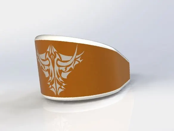
Pedal:-
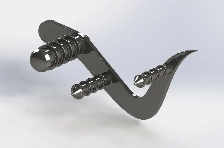
Rear Wheel:-
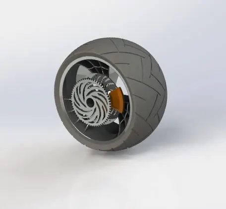
Read Fender:-
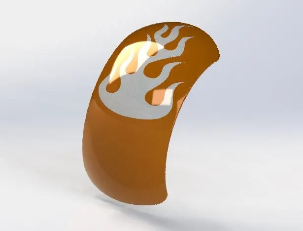
Transmission Belt:-
American Chopper:-
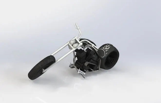
Assembly Model Screenshots:-
Front View:-
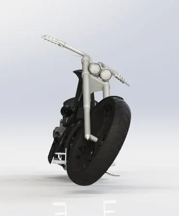
BackView:-
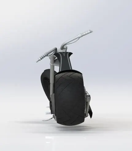
Isometric View:-
Right View:-
Left View:-
Top View:-
Camera View:-
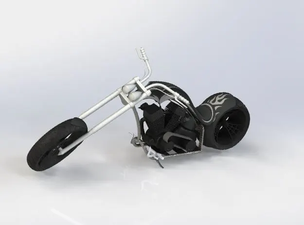
PHOTO VIEW 360 was used instead of rendering as there was no sufficient visual support with regard to rendering.
Conclusion:-
The learning was really a great experience using the Solid Works software. The designing of the parts, their assembly, and rendering have provided significant knowledge of Solid Works. Received adequate knowledge on the design and assembly of the American Chopper.