Photo Realistic Rendering
AMERICAN CHOPPER USING SOLIDWORKS
1) OBJECTIVE :
The objective is to learn how to use SOLIDWORKS software user interface by modelling an AMERICAN CHOPPER BIKE.
- It also has an objective of teaching how to view the model in realistic view using PHOTO VIEW 360 which helps in better rendering process.
2) INTRODUCTION :
- To design this American Chopper Bike, We need to model various parts with proper dimensions and alignment’s, and assemble them together to make the complete bike.
- The various parts that to be modelled are :-
- TRANSMISSION BELT
- KICKSTAND
- FRONT FENDER
- REAR FENDER
- CHAIN
- OIL TANK
- PEDAL
- FRONT WHEEL
- REAR WHEEL
- FRONT FORK
- CHASSIS
- ENGINE
- GAS TANK.
3) APPROACH TO DESIGN / METHODOLOGY :
- The American Chopper is designed by modelling all the parts of the bike.
- All the modelled parts should then be Assembled
- The assembled bike then should be given proper Colour, Decals and good appearance.
- Finally, rendering the bike using Photo View 360.
4) DESCRIPTION :
- Modelling all these parts were created by using various features, like:
- PLANES :
This is where we can adjust our model in various planes and help us sketch comfortably within the plane view. The plane views are:
- Front Plane :
This plane helps in creating the sketch or assembly keeping the front view as its main perspective.
- Top Plane :
This plane helps in creating the sketch or assembly keeping the top view as its main perspective.
- Right Plane :
This plane helps in creating the sketch or assembly keeping the right view as its main perspective.
- SKETCH :
This feature is used to use various tools, such as:
- Smart Dimension :
This tool is used to give proper dimensions to the sketch or model and is very handy to use.
- Geometrical features :
This tool is used to sketch in the plane by using various tools like, Line, Circle, Rectangle, Sketch Fillet, Arc etc., and is very handy to use.
- Trim Entities :
This tool is used to Trim the extra lines or entities which can automatically or easily delete the open line or sketch which needs to be erased and is very handy to use.
- Convert Entities :
This tool is used to convert the sketch that is already fully defined, which can be used as the further reference points and can be re-sketched easily.
- Offset Entities :
This tool is used to create an offset of the sketch and can be created inside the sketch or outside the sketch and is very handy to use.
- Mirror Entities :
This tool is used to mirror the sketch drawn on the plane which can be mirrored according to the reference planes and is very handy to use.
- Linear Sketch Pattern :
This tool is used to create a pattern to a sketch which saves time by not creating the same sketch again and again. This also includes linear pattern or circular pattern and is very handy to use.
- Display Relations :
This tool is used to display all the relations that were assigned during the sketch which can be also modified at any time.
- FEATURES :
- Extruded Boss/Base :
This tool is used to extrude the 2-D sketch into 3-D sketch.
- Revolved Boss/Base :
This tool is used to revolve the 2-D sketch making it 3-D.
- Extruded Cut :
This tool is used to cut the existing 3-D part according to the 2-D sketch drawn on it.
- Revolved Cut :
This tool is used to cut the existing 3-D part according to 3-D sketch drawn on it.
- Fillet :
This tool is used to fillet the edges of the part which makes the sharp edges of the part look curved.
- Chamfer :
This tool is used to create a beveled feature on the edges, faces or vertex of the part.
- Linear pattern :
This tool is used to pattern the features or faces in one or two linear pattern and also has an option of creating the pattern in circular.
- Dome :
This tool is used to create a dome shape on the surface selected and can be shaped both inwards and outwards.
- All the above features and tools are used while modelling the American Chopper and also very handy to learn and use.
5) FINDING / RESULTS :
- The parts that are designed are as follows :
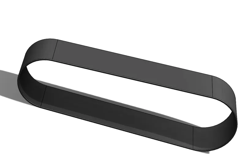
- TRANSMISSION BELT
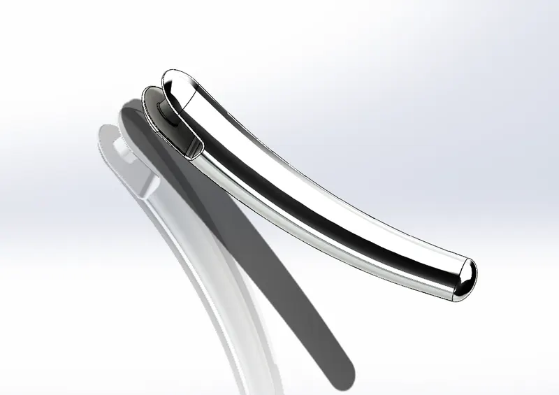
- KICKSTAND
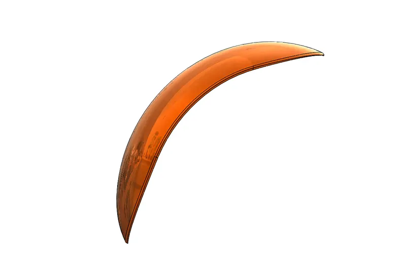
- FRONT FENDER
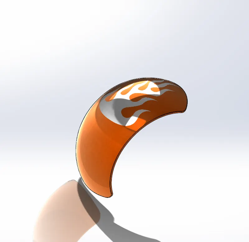
- REAR FENDER
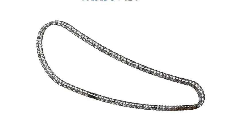
- CHAIN
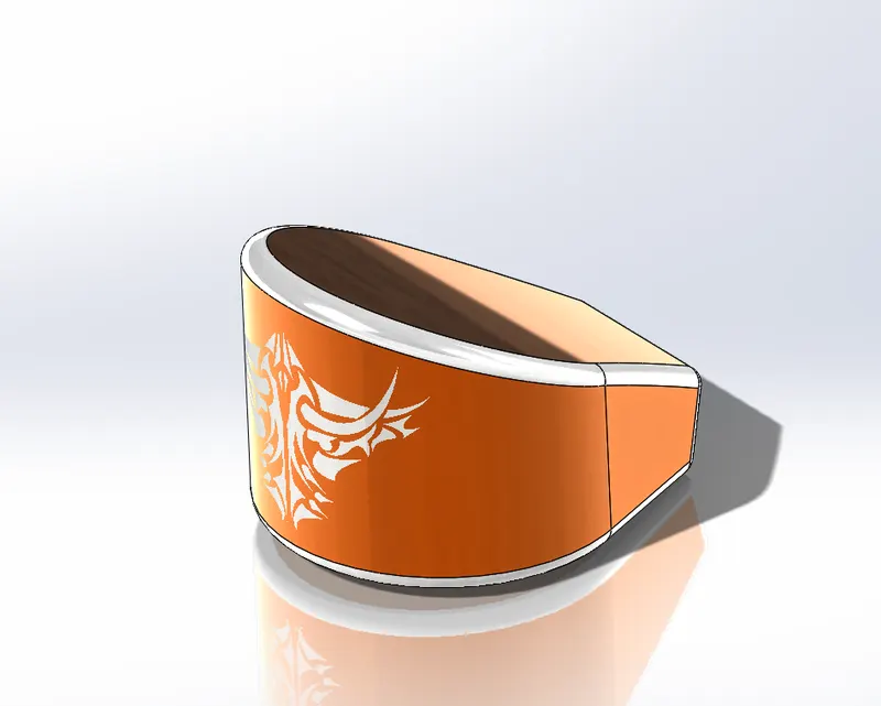
- OIL TANK
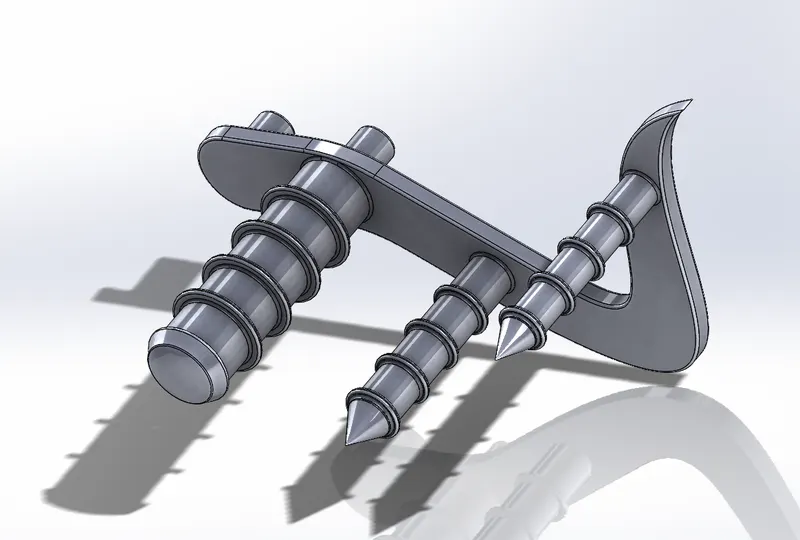
- PEDAL
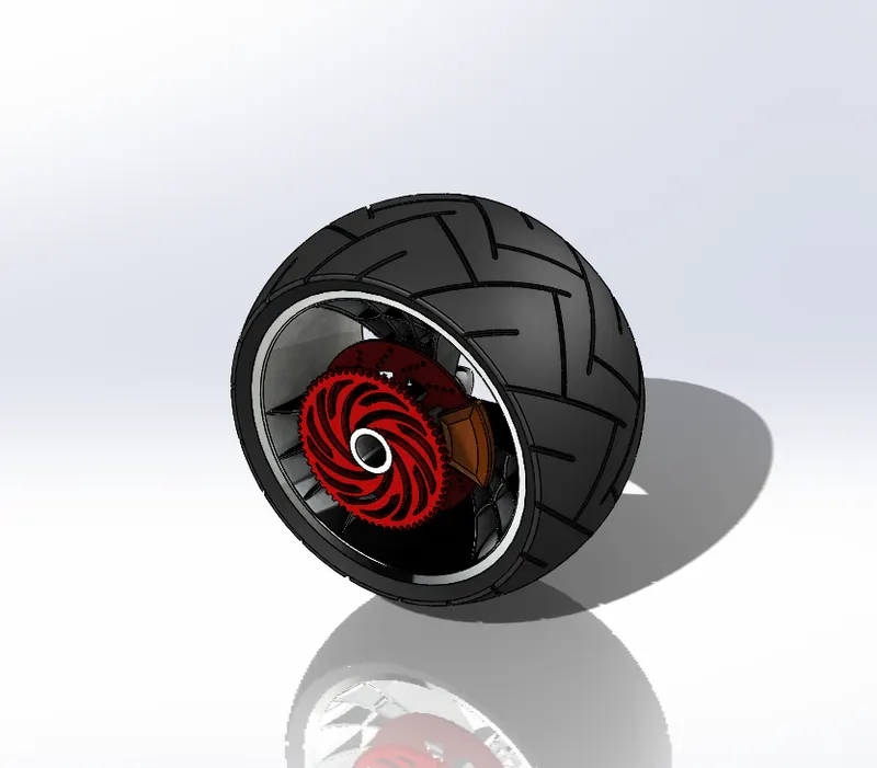
- FRONT WHEEL
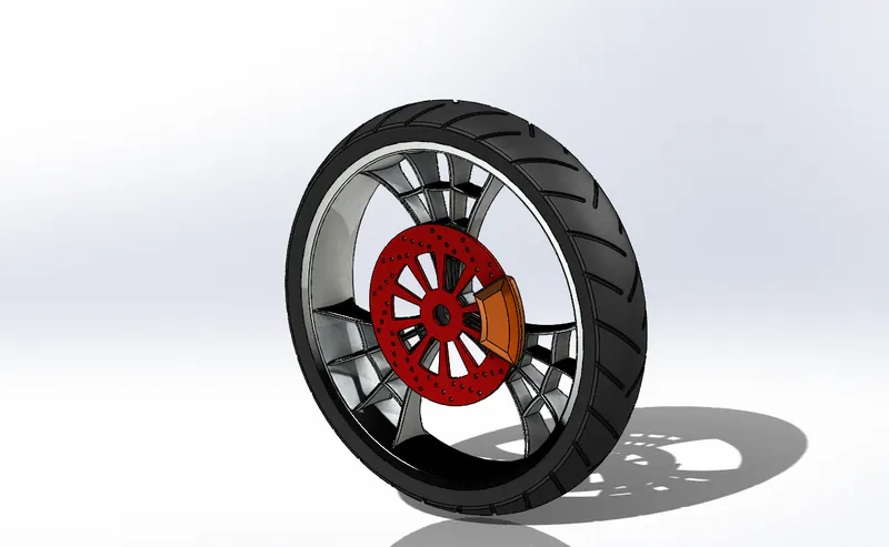
- REAR WHEEL
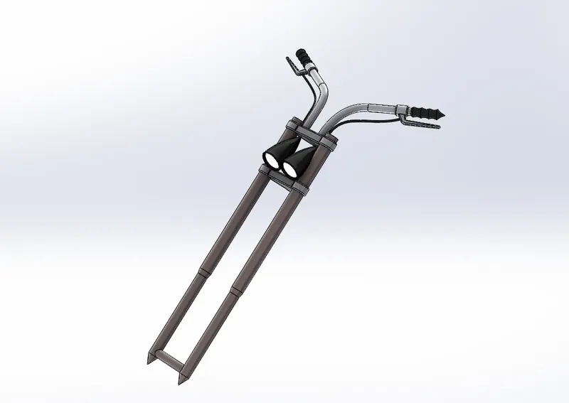
- FRONT FORK
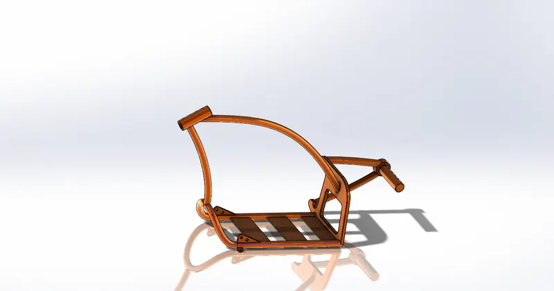
- CHASSIS
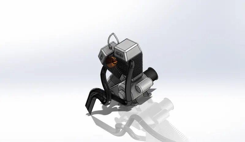
- ENGINE
- GAS TANK
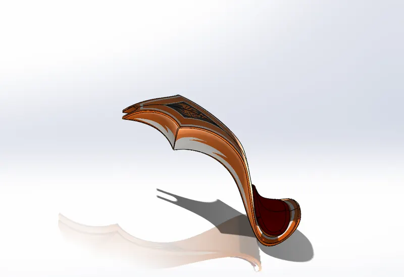
- ASSEMBLED AMERICAN CHOPPER
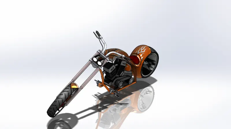 6) RENDERING :
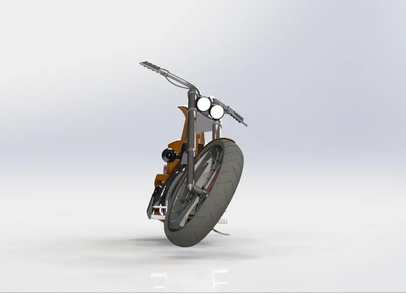
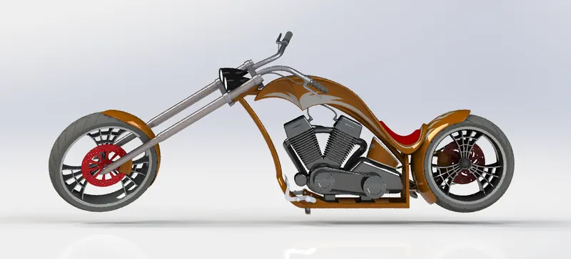
- Rendering was done using PHOTO VIEW 360 as there was no visual support.
- Rendered American Chopper Front View :
- Rendered American Chopper Side View :
- Rendered American Chopper Top View :
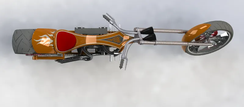
- Rendered American Chopper Isometric View :
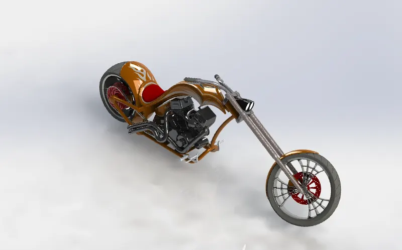
- Rendered American Chopper Camera View :
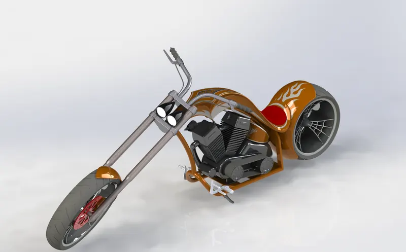
- Rendered American Chopper View with Scene:
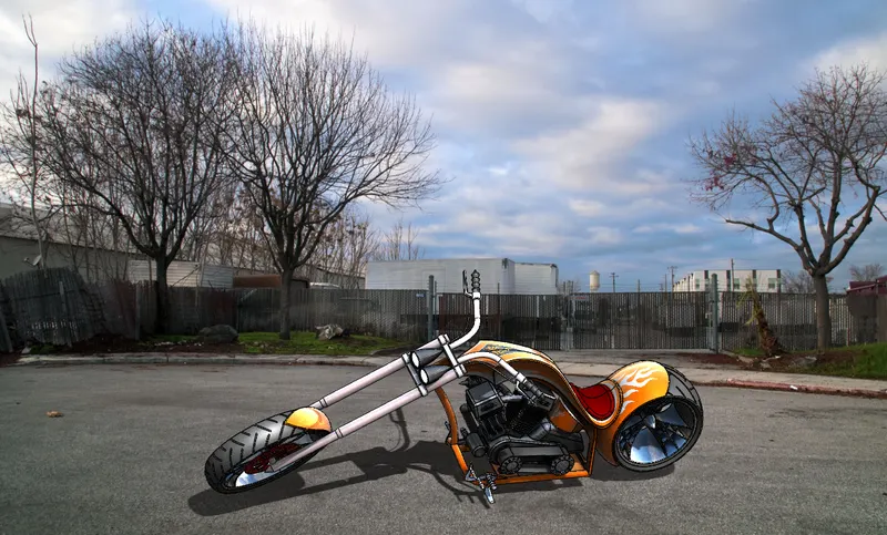
7) DISCUSSIONS :
- The Video support on how to design the parts with proper dimensions and assembly was very helpful.
- Each part was divided into multiple videos, making the user feel comfortable by different setting options.
- ‘Challenges’ are one more special features here, which makes us not only to learn watching the video but also a place where we submit the tasks within a sufficient period of time.
- All the support engineers and mentor were available to their best, making sure that I have all my queries cleared within very short period of time.
8) CONCLUSIONS :
- Finally, I Conclude that it was great learning the user interface of SOLIDWORKS by Modelling and Rendering the AMERICAN CHOPPER.