Photo Realistic Rendering
1. Title: DESIGNING, MODELLING & RENDERING OF AMERICAN CHOPPER BIKE
2. Objective:
- To learn the Solidworks Interface, sketch & design of the American chopper.
- To learn to assemble the final parts/models of the American chopper.
- To make a photorealistic rendering of the designed bike using Photoview 360 & SolidWorks Visualize.
Softwares Used: SolidWorks2020 & SolidWorks Visualize 2020
3. Introduction:
SolidWorks: is a solid modeling computer-aided design (CAD) and computer-aided engineering (CAE) computer program that runs primarily on Microsoft Windows. While it is possible to run SolidWorks on MacOS, it is not supported by SolidWorks. SolidWorks is published by Dassault Systèmes.
American Chopper: A chopper is a type of custom motorcycle. The chopper is perhaps the most extreme of all custom styles, often using radically modified steering angles and lengthened forks for a stretched-out appearance. Some of the characteristic features of choppers are long front ends with extended forks often coupled with an increased rake angle, hardtail frames (frames without rear suspension), very tall "ape hanger" or very short "drag" handlebars, lengthened or stretched frames, and larger than stock front wheels.
The first choppers were built in America and tended to be based on Harley-Davidson motorcycles. Rather than being primarily performance-oriented modifications, choppers are more about achieving a certain look. So the purpose of this project is to create an aesthetic model of a chopper using Solidworks and Solidworks Visualize.
4. Design Methodology:
=> Flowchart:
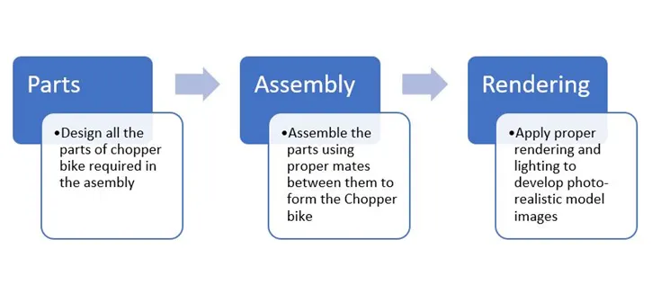
As bikes have various components, first we need to design all the components of the bike. Then to design the bike, we need to assemble all the parts with proper mates (relations) between them, to form the assembly. Further, the assembly is given appropriate appearances and lighting effects to produce photo-realistic rendering images of the assembly.
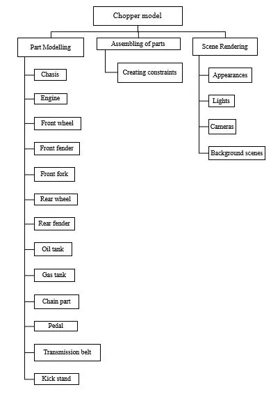
=> Commands Used:
- 2d sketch: 2d sketch is the basic command which takes one to the sketching template. It is here where we make the sketches required to make a solid body or part. We have to select a plane from 3 predefined planes namely Front Plane, Top Plane, and Right plane.
- 3d sketch: In 3d sketch, we sketch a 3dimensional space rather than in a 2dimensional plane.
- Splines: The SOLIDWORKS software supports two types of splines, B-splines and style splines. You can use B-splines to create complex curves. You can define and modify them using several controls, including spline points, spline handles, and control polygons. A single B-spline can have multiple through points and spans (the region between through points). You can apply curvature constraints at each endpoint. At each point, you can weigh the tangency vector and control the tangency direction. Style splines, based on Bezier curves, are a good option when it is important to have a smooth curve (that is, to assure curvature continuity). You define and control the curves using control vertices. The control vertices form a control polygon or hull of the curve. There are no through points, so a style spline has only one span between the endpoints. You can inference style splines for tangency or equal curvature. You can constrain the points and dimension the curves' sides. These curves also support mirroring and self-symmetry.
- Sketch Fillet: The Sketch Fillet tool trims away the corner at the intersection of two sketch entities to create a tangent arc. This tool is available for both 2D and 3D sketches. The Fillet tool on the Features toolbar fillets entities such as edges in parts. The two corners of the rectangle are filleted with the same radius and with Keep constrained corners selected.
- Ellipse: The Ellipse tool to create a complete ellipse. Use the Partial Ellipse tool to create an elliptical arc.
- Fillets: Fillet/Round creates a rounded internal or external face on the part. You can fillet all edges of a face, selected sets of faces, selected edges, or edge loops.
- Sketch Fillets: The Sketch Fillet tool trims away the corner at the intersection of two sketch entities to create a tangent arc. This tool is available for both 2D and 3D sketches. The Fillet tool on the Features toolbar fillets entities such as edges in parts. The two corners of the rectangle are filleted with the same radius and with Keep constrained corners selected.
- Boss Extrude: creates a solid based on the sketch.
- Cut Extrude: cut out of the existing solid body.
- Revolve Boss: evolves add or remove material by revolving one or more profiles around a centreline. You can create revolved boss/bases, revolved cuts, or revolved surfaces. The revolving feature can be a solid, a thin feature, or a surface. The sketch must be a 2d sketch, not a 3d sketch. Axis of revolution can be 3d sketch.
- Revolve Cut: does a cut w.r.t an axis of rotation according to sketch made.
- Sweeps: Sweep creates a base, boss, cut, or surface by moving a profile (section) along a path. A sweep can be simple or complex. To generate the swept geometry, the software creates a series of intermediate sections made by replicating a profile at various positions along the path. The intermediate sections are then blended. Additional parameters can be included in the sweep feature such as guide curves, profile orientation options, and twist to create a wide variety of shapes.
- Loft: Loft creates a feature by making transitions between profiles. A loft can be a base, boss, cut, or surface. You create a loft using two or more profiles. Only the first, last, or first and last profiles can be points. All sketch entities, including guide curves and profiles, can be contained in a single 3D sketch.
- Chamfer: The chamfer tool creates a beveled feature on selected edges, faces, or a vertex.
- Shell: The shell tool hollows out a part, leaves open the faces you select, and creates thin-walled features on the remaining faces. If you do not select any face on the model, you can shell a solid part, creating a closed, hollow model. You can also shell a model using multiple thicknesses.
- Dome: Creates a dome on the face selected.
- Linear Pattern: The Linear Pattern Property Manager appears when you pattern one or more features along one or two linear paths.
- Circular Pattern: The Circular Pattern Property Manager appears when you pattern one or more features around an axis.Sketch Driven Pattern: Using sketch points within a sketch, you can specify a feature pattern. The seed feature propagates throughout the pattern to each point in the sketch. You can use sketch-driven patterns for holes or other feature instances.
- Split: You can split a sketch entity to create two sketch entities. Conversely, you can delete a split point to combine two sketch entities into a single sketch entity. Use two split points to split a circle, full ellipse, or a closed spline.
- Project Curve: The projected curve will be available under the feature tab. The project curves command can be used to create a 3D curve. The 3D curve can be created by using the reference of two 2D curves.
- Extend: You can add to the length of a sketch entity (line, centreline, or arc). Use Extend Entities to extend a sketch entity to meet another sketch entity.
- Convert Entities: You can create one or more curves in a sketch by projecting an edge, loop, face, curve, or external sketch contour, set of edges, or set of sketch curves onto the sketch plane.
- Trim: Select the trim type based on the entities you want to trim or extend. All trim types are available with 2D sketches and 2D sketches on 3D planes.
- Mirror: Select Mirror Entities to mirror pre-existing 2D sketch entities on a plane, and then select the entity about which to mirror. If you want to first select the entity about which to mirror, and then sketch the entities to mirror, select Dynamic Mirror Entities.
- Sketch Picture: Sketch pictures are used as a reference to draw sketches.
- Sketch Pattern: Create linear or circular sketch patterns using elements from sketch entities you intend to pattern or model edges.
- Dynamic Mirror Sketch Entities: Select the Dynamic Mirror Entities tool to first select the entity about which to mirror, and then sketch the entities to mirror.
5. Methodology: (Description of each part/model)
>> Transmission Belt:
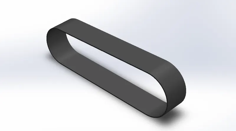
A transmission belt is a loop of flexible material used to transmit power by the means of pulleys. Belts transmit power efficiently through the pulleys. They are one of the cheapest means used power transmission. other advantages are noiseless working, shock absorption during working, no lubrication, minimal maintenance, high tolerance for misalignment. Transmission Belt is the first part taught in this ultimate SolidWorks tutorial.
Features used
- Sketch
- Offset
- Extrude
- Fillet
- Appearance
Methodology
-Select the front plane and click on the line tool from the Sketch tab.
-Draw a line from the origin to the right and at the end draw an arc tangent to the line drawn.
-From the end of the first arc draw another line towards the left and draw another arc such a way that it joins that starting point of the first line.
-Check the sketch relations using the symbols on the joints. Then correct the relations.
-After correcting the relations give the dimensions to each of the lines using the Smart Dimension tool.
-Then draw the same shape offset from the original figure using the Offset Entities option.
-Now create an extrusion of the shape using Extrude Boss/Base tool from the Features tab.
-Create a fillet throughout the edges of the part using the Fillet tool.
-After creating part five a matte black appearance to the part using the Appearances tool.
-Now save the project as a SolidWorks part file.
>> Kickstand:
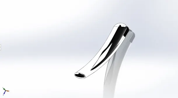
The kickstand is a device used to keep the bike in an upright position. It is a metal piece that flips down to touch the ground and provide support.
Features used
- 2d sketch
- ellipse
- spline
- pierce
- loft
- cut extrude
- Boss extrudes
- split
Methodology
-First draw an ellipse in the front plane using the Ellipse tool and align it with the origin.
-Then create a spline from the origin in the midplane using the Spline tool and give dimensions to it.
-Now generate a new plane normal to the spline using the Plane tool from Reference Geometry.
-Then create another ellipse on the newly generated plane such that its center aligns with the ending of the spline.
-After that using the Lofted Boss/Base tool generate a solid by clicking on the two ellipses and then using Centerline Parameters to make the solid align with the spline.
-Then make 2 domes on either side of the part using the Dome feature from the Features tab in the given dimensions.
-Now on one side make an extruded cut by drawing a rectangle on the Mid Plane and then extruding it by the Through All-Both option.
-After that draw a line on the plane that was created previously using the Midpoint Line tool and align it horizontally and vertically with the origin.
-Then using the Split features from the Features tab slice of a small piece of the part.
-Now using Extruded Boss/Base tool extrude a circle that is drawn on the Top plane by selecting the Up To Next option for both directions.
-After that for creating fillets on the parts, select the Fillet tool and click on the edges where the fillets have to make.
-Finally, a chrome appearance is given to the part using the Appearances, Scenes, and Decals tab.
-Save and close.
>> Chain:
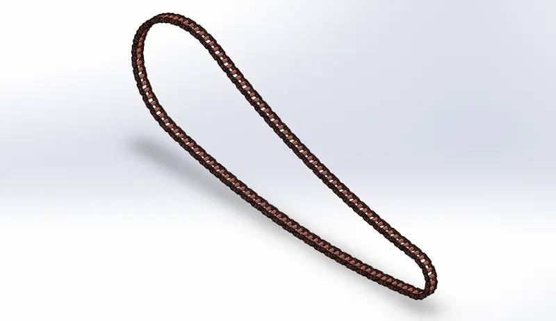
The Chain drive is a mechanism to transfer power from one place to another, similar to a transmission belt. The chain drive is a positive drive mechanism since there is no slippage between the belt and gear. Drives are mostly made of metal, followed by plastic and rubber. They are very efficient in power transmission. Lubrication is one of the most important points since the drives wear out quickly without proper lubrication. Chain drives suffer from speed controlling since the drives are made from metal, they have significant self-weight which gives rise to inertia during rotation. Therefore, special care has to be taken to avoid such situations, which in turn will reduce the chances of vibration and increase the life of the chain drive. In most cases, either the shafts are accelerated and deaccelerated accordingly, or the sprocket is speed controlled. Chains are often narrower than belts, and this can make it easier to shift them to larger or smaller gears to vary the gear ratio. Multi-speed bicycles with derailleurs make use of this. Also, the more positive meshing of a chain makes it easier to build gears that can increase or shrink in diameter, again altering the gear ratio.
Features used
- 2d sketch
- circles
- 3point arc
- Slot
- Block
- Fillet
- Curve Pattern
- Mirror
Methodology
-First, start sketching on the midplane by drawing two circles and connecting them. Then remove the unwanted lines using the Trim Entities tool.
-After that in the same plane draw the two chain links and save them as blocks.
-Then using the Insert Block tool add the links and extrude them and give fillets to each pin that are created. Then to copy the parts throughout the lines use the Curve Driven Pattern tool and then select the lines to need.
-After that select all the pins parts from the Solid Bodies sub menu and add them to a folder.
-Then using the mirror option create the joints on the other side of the plane too.
-Now to change the appearance use the appearance tool and then finally save the project.
>> Engine:
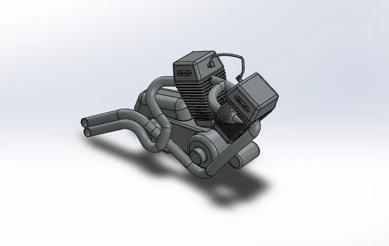
A motorcycle engine is an engine that powers a motorcycle. Motorcycle engines are typically two-stroke or four-stroke internal combustion engines, but other engine types, such as Wankel’s and electric motors, have been used. Although some mopeds, such as the VéloSoleX, had friction drive to the front tire, a motorcycle engine normally drives the rear wheel, power being sent to the driven wheel by belt, chain, or shaft. Historically, some 2,000 units of the Megola were produced between 1921-1925 with front-wheel drive, and the modern Rokon, an all-terrain motorcycle with both wheels driven, has been produced since 1960. Most engines have a gearbox with up to six ratios. Reverse gear is occasionally found on heavy tourers, for example, the Honda GL1600, and sidecar motorcycles, such as the Ural. The rider changes gears on most motorcycles using a foot pedal and manual clutch, but early models had hand levers. More recently, some have automatic or semi-automatic gearboxes.
Features used
- Extrude
- Revolve
- Dome
- Fillet
- Chamfer
- Pattern
- Mirror
- Split
- Combine
- Sweep
Methodology
-First, the blueprint of the motorcycle is added to the front plane.
-After that various sketches are drawn on the front plane and are then extruded and fillets are given.
-Now a sketch is drawn on the right plane and is revolved to make a part.
-Then make a new plane with respect to the right plane and draw a sketch on the plane and revolve.
-After that sketch the front plane and extrude.
-Now using the circular patter option make the teeth for the chain.
-Similarly, do the same for the other sprocket.
-After that create domes on the parts that are created.
-Then a sketch is drawn on the front plane and is cut extruded to make holes on the sprocket. A similar step is done on the other sprocket too.
-Now certain fillets and chamfer are given to the parts.
-After that, another sketch is drawn on the front plane and is then extruded. After that one more sketch is drawn on the same plane to make a connecting part.
-Then a new sketch is drawn on the front plane and a new plane is created with respect to the sketch that is drawn.
-Now a sketch is drawn on the newly created plane and is then extruded.
-Again two more sketches are drawn on the newly created plane and are then extruded.
-After that fillets and chamfers are given to various sides.
-Then a sketch is drawn on the same plane and is then cut extruded to create a shape.
-To copy this shape throughout the part, the linear pattern option is used.
-After that various fillets are applied.
-Then a sketch is drawn on the cylinder that is created and is then extruded outward and a dome is given.
-This shape is mirrored on either side of the cylinder.
-After that, a sketch is drawn on the front plane and is then extruded and fillets are applied.
-Then using the split option some parts are removed.
-After that copy the cylinder on the other side using the mirror tool.
-Now some fillets are given to the edges.
-Then some sketches are drawn on the top plane and are extruded and certain fillets are given.
-After that sketches are drawn on the front plane and are then extruded and chamfered.
-Now a small sketch is drawn on the sprocket created and is then extruded cut and the fillet is given.
-Then using the circular pattern option copy the cut throughout the sprocket.
-Again some chamfers are given.
-After that, another sketch is drawn on the front plane and another on the right plane.
-Then it is swept using the sweep tool to make the exhaust tube.
-After that, the tube is mirrored.
-Now all the made parts are combined.
-Then a plane is created with respect to the top plane.
-Then another sketch is drawn on the front plane and a curve is drawn on that is created previously. This sketch is used to make a swept part.
-Again a sketch is drawn on the front plane and is revolved to make the air intake.
-Various filets are applied to the part.
-Then a sketch is drawn on the top plane and is then cut extruded and using the circular pattern tool the cut is copied throughout the part.
-Then to make the exhaust tube 4 curves are drawn on two different planes and using the projected curves option make a curve and using the swept option make a sweeping part.
-Similarly, make another part using the same procedure.
-After that, a sketch is drawn on the top plane so that it can be used to cut the exhaust tip using the split tool.
-Then sketch the face of the spark plug and another curve on the front plane so that it can be used to make the wire for the spark plug.
-Similarly, make the same wire on the other spark plug using the same procedure as above.
>> Front Fender:
Fender is a part of automobiles that covers the wheel. The fender's function is to contain various materials such as stones, mud, liquids on the roads which otherwise would have sprayed themselves onto the inside of the car or the pedestrian behind the car. The front fender is used for the front wheel and the rear fender is used for the rear wheel. The fender is also known as a mudguard.
Features used
- Revolve
- Split
- Fillet
Methodology
-First Draw a 3-Point arc on the Front Plane using the 3 Point Arc tool from Sketch Tab with the given dimensions.
-Then make another offset arc towards inward using the Offset Entities tool from Sketch Tab.
-Then join the two arcs using the line tool and the Trim Entities tool.
-After that draw line from the center on the same plane and make it's one end vertical to one end of the arc.
-Then using the Revolve tool revolve the Shape to create a front fender part.
-For giving an appearance using the appearance tool and then select Siena from the Plastic tool.
-Now draw another arc in the Top plane on either side of a line drawn from the origin using the Dynamic Mirror tool and select the Split tool from the features list and then trim the part that is not needed.
-Similarly, draw another arc on the Front Plane and the using Split tool remove the remaining material.
-Then using the fillet tool round the edges of the part.
-Finally, save the part.
>> Rear Fender:
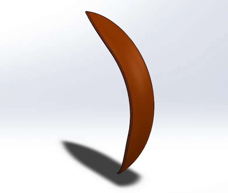
Fender is part of automobiles that frames the wheel. The fender's purpose is to contain various materials such as stones, mud, liquids on the roads which otherwise would have sprayed itself onto the inside of the car or the pedestrian behind the car. The front fender is used for the front wheel and the rear fender is used for the rear wheel. The fender is also known as a mudguard.
Features used
- Revolve
- Split
- Fillet
- Shell
Methodology
-First Draw a 3-Point arc on the Front Plane using the 3 Point Arc tool from Sketch Tab with the given dimensions.
-Then make another offset arc towards inward using the Offset Entities tool from Sketch Tab.
-Then join the two arcs using the line tool and the Trim Entities tool.
-After that draw line from the center on the same plane and make it's one end vertical to one end of the arc.
-Then using the Revolve tool revolve the Shape to create a rear fender part.
-For giving an appearance using the appearance tool and then select Siena from the Plastic tool.
-Now draw another arc in the Top plane and select the Split tool from the features list and then trim the part that is not needed.
-Then using the fillet tool round the edges of the part.
-Finally, save the part.
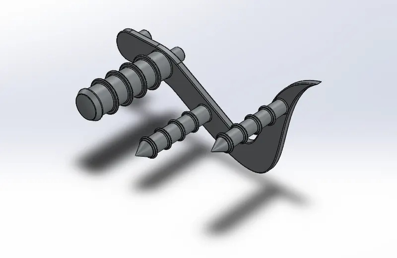
>> Pedal:
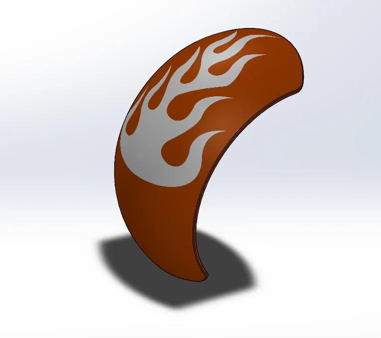
Foot pedals can be developed or manufactured from a variety of materials; some are made from aluminum, steel, and also titanium. Some of them can assume a stamped, cast, mechanized, or forged form. Most of the above foot pedals are both heats treated, or they are anodized. The majority of the great foot pedals have been drilled polished or ground they are then floor and put together. We have main facets of foot pedals that aa the charge of mud retention. These are draft, thickness, nooks and crannies. Let us seem to be at each of them and how it influences mud retention. Pedals are used to operate brakes or switch gears in the vehicle.
Features used
- Extrude
- Fillet
- Dome
- Chamfer
- Pattern
Methodology
-First sketch the given shape using the given geometry on the Front plane using various tools like Line,Circle and Spline tools.
-After that extrude the shape to a given distance. Then extrude the two smaller circles on one side to a particular distance.
-Now give fillets to the first piece that we have created. After that draw a sketch on the top plane using construction line and normal line.
-Then Revolve that shape concerning the construction line.
-Now create a dome over that revolved part using the Dome tool from the features list.
-After that give fillets to the dome edges and the small circle extrusions that were previously created.
-Then Extrude the other two circles on the same side as that of the revolved extrusion.
-Now give Chamfer to both the newly created extrusions using the Chamfer tool.
-After that draw an offset sketch of the outer edges of the newly created extrusions on the Front Plane and then extrude it with an offset.
-Then give fillet to it and using the Linear Pattern method copy the extrusions across the parts.
-Finally, give fillets to wherever necessary.
>> Front Fork:
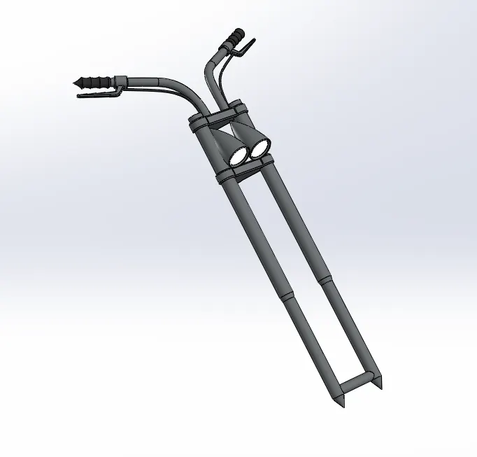
The element which connects the front wheel and axle to the rest of the frame is known as a front fork. The tripe clamp or yoke is one of the main parts of the front fork. The front fork contains a front brake and front suspension. The fork and its attachment points on the frame establish the critical geometric parameters of rake and trail, which play a major role in defining how a motorcycle handles and dives during braking.
Features used
- Revolve
- Extrude
- Pattern
- Dome
- Fillet
- Sweep
- Projected curve
- Combine
Methodology
-Start by drawing the shape of the fork on the front plane and then revolving it to form the fork.
-After that draw another shape on the right plane and then extrude it. Now fillets are given to different edges.
-Then using the Linear pattern tool make 1 copy of the part.
-Now draw a circle on the front plane to make an extrude that joins the ends of the fork.
-After that draw another sketch on the part that was previously created and is then extruded to connect the copies of the part.
-Then a sketch is drawn on the front plane that can be revolved to make the headlamp of the motorcycle.
-After that draw, a sketch on the part to make a small extrude for the light and fillet is given on the edges.
-Now to create the bulb-like shape to the light a dome is created on the extruded surface.
-Agan certain fillets are applied and then a sketch is created on the front plane to create a chamfer on the inside of the headlight.
-After then using the Body Move option the light is moved at a particular distance and angle.
-Then a curve is drawn using the spline tool on the front plane and another spline also. Then using the projected curve option a resulting curve is obtained.
-After that, a circle is drawn on the handle joint and is used to create the handles of the chopper bike Sweeping through the projected curve from the circle.
-Now to create a plane a sketch is drawn on the end of the handle.
-Then a sketch is drawn on the newly created plane and is then revolved cut.
-After that, another sketch is made on the top plane that is revolved over the handle.
-Again another plane is created on the handle to sketch the brake lever.
-After sketching it is extruded and the fillet is applied.
-Then by using the projected curves tool, the brake cable is created by drawing splines and a circle that is swept to form the cable.
-Now the whole part is mirrored about the face of the handle joint.
-And many parts are combined using the combine tool and each of the parts is given its appearances using the Appearance tool
>> Front Wheel:
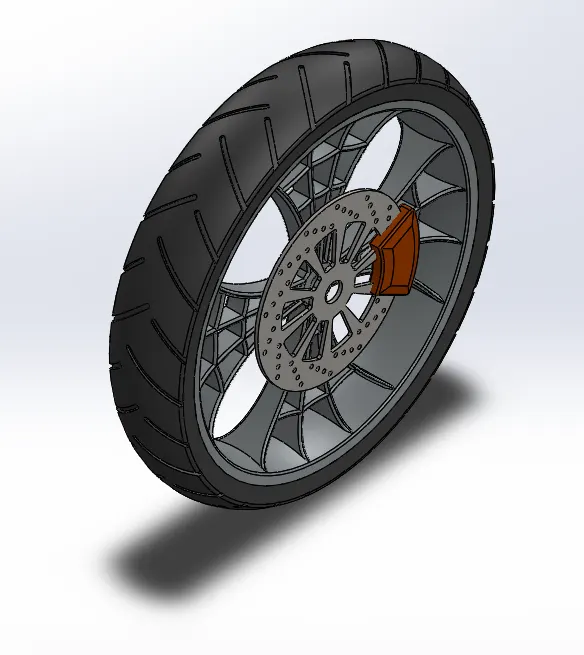
A wheel may be a circular block of a tough and sturdy material at whose center has been bored a circular hole through that is placed Associate in Nursing shaft bearing concerning that the wheel rotates once an instant is applied by gravity or torsion to the wheel concerning its axis, thereby creating along with one in all the six straightforward machines. once placed vertically below a supporting platform or case, the wheel turning on the horizontal shaft makes it doable to move significant loads; once placed horizontally, the wheel turning on its vertical shaft makes it doable to regulate the spinning motion accustomed form materials (e.g. a potter's wheel); once mounted on a column connected to a rudder or a chassis mounted on different wheels, one will manage the direction of a vessel or vehicle (e.g. a ship's wheel or steering wheel); once connected to a crank or engine, a wheel will store, release, or transmit energy (e.g. the flywheel).
Features used
- Revolve
- Spline
- Extend
- Trim
- Cut extrude
- Offset
- Cut revolve
- Circular pattern
- Chamfer
- Fillet
- Corner center point rectangle
Methodology
-Start sketching on the front plane and draw two shapes on the plane -one for the rim and the other for the center part and revolve it.
-Then on the Right plane sketch, the shape of the wheel spoke using the Spline and Line tools and then extrude it.
-After that draw another sketch on the same plane and use the extrude cut tool to create cuts in the shape that is created.
-Then draw another sketch in the same plane to make a web-like shape that has to be extruded using the Extrude Boss/Base tool.
-Now sketch the Front Plane to cut some parts of the spokes and the center part of the wheel.
-Using the Circular Pattern tool create the same spokes throughout the wheel.
-Then Combine the spokes and the center part using the combine tool.
-After that give fillets to the combined part using the Fillet tool.
-Now for creating the disc, we have to draw a circle on the Right plane and then extrude with the offset option turned on.
-Then to give holes to the disc draw a sketch on the Right plane and then the Extrude Cut option is selected.
-After that using the Circular Pattern tool copy the Extrude cuts throughout the disc.
-Again draw another sketch on the same plane and the Extrude Cut option is selected and then a fillet is created for the cut.
-After that again the Circular Pattern option is selected.
-A hole is created in the disc as well as the Centre part by drawing a circle on the right plane and by selecting the extrude cut option.
-A new part called the caliper is created by sketching a shape on the Right plane and extruding it. Then Chamfers are given on both the faces of the caliper.
-After that various fillets are given to the part.
-Now for creating the tire, a shape is drawn on the Front Plane at a particular distance from the origin and is then revolved.
-Then for creating threads on the tire patterns are drawn using the Rectangle Tool on the Front Plane and the using Extrude cut material is removed to make the pattern.
-After that fillets are given to the inner edge of the pattern and using the Circular Pattern tool the threads are copied throughout the surface of the tire.
-Then Appearance is given to different parts using the Appearance tool and then the document is saved.
>> Rear Wheel:
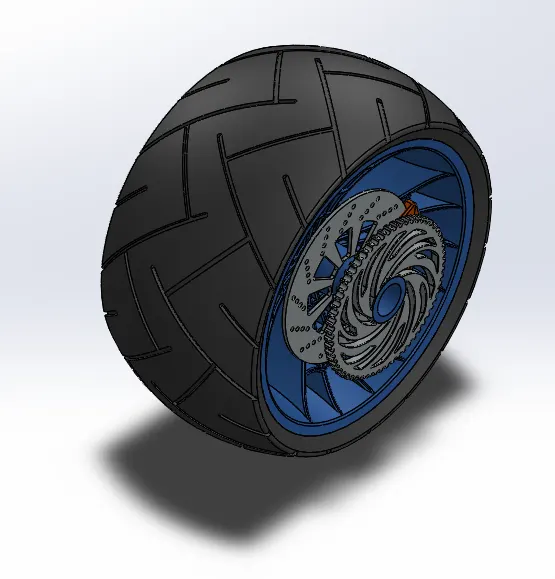
A wheel may be a circular block of a tough and sturdy material at whose center has been bored a circular hole through that is placed Associate in Nursing shaft bearing concerning that the wheel rotates once an instant is applied by gravity or torsion to the wheel concerning its axis, thereby creating along with one in all the six straightforward machines. once placed vertically below a supporting platform or case, the wheel turning on the horizontal shaft makes it doable to move significant loads; once placed horizontally, the wheel turning on its vertical shaft makes it doable to regulate the spinning motion accustomed form materials (e.g. a potter's wheel); once mounted on a column connected to a rudder or a chassis mounted on different wheels, one will manage the direction of a vessel or vehicle (e.g. a ship's wheel or steering wheel) once connected to a crank or engine, a wheel will store, release, or transmit energy (e.g. the flywheel).
Features used
- Revolve
- Spline
- Extend
- Trim
- Cut extrude
- Offset
- Cut revolve
- Circular pattern
- Chamfer
- Fillet
- Corner center point rectangle
Methodology
-First, draw a shape on the front plane so that it can be revolved at a particular axis to form the rim of the rear wheel and the shaft of the rear wheel.
-After that on the right plane draw an arc using the 3 Point arc tool and make a shape and then it is extruded at a particular distance from the middle towards either side of the plane.
-Again draw certain shapes on the right plane using drawing tools and then using the Extruded cut option to make spokes for the rim.
-Then draw arcs that connect the spokes on the same plane and extrude them.
-Now using the Circular Pattern tool select the spoke that was made previously and then by selecting an axis to make more of the same spoke throughout the rim.
-After that combine all the parts(rim, spokes, and the shaft).
-Then start a new sketch on the front plane after selecting the intersection curve option on the rim for that plane. Now draw a shape so that it can be used to extrude cut a certain amount of materials from the spokes and the shaft.
-Now give fillets to the spokes and other parts that are created till now.
-After that to generate a hole at the center of the rim draw a small circle on the right plane and then use the extrude cut option.
-Then draw another sketch on the front plane and is then revolved to create the part that forms the shaft.
-Now draw another circle on the right plane and then extrude it with an offset. And this forms the disc for the brakes and to make holes another shape is drawn on the plane of the disc. Then using the linear pattern option make 4 of them at a particular angle. Now extrude cut all 4 of them.
-After that using the circular pattern tool create the same holes throughout the disc.
-Then sketch the same disc plane and using the circular pattern tool make copies of it throughout the disc.
-After that fillets are given to the parts that are created above.
-Now on the right plane sketch the caliper and is extruded. Then Chamfers are given to either side of the chamfer.
-Then fillets are given certain edges of the caliper.
-After that, to make the sprocket for the chain a circle is drawn on the right plane and is extruded and is given chamfers on the edges.
-Now another sketch is drawn on the plane of the sprocket to create the cut for the gear and each of the cuts is copied throughout the part using the circular pattern option.
-After that, another pattern is drawn and extruded on the same plane to create a design on the sprocket.
-Again the fillets are given to the sprocket.
-Then to create the tire for the rear wheel, a sketch is drawn on the front plane and is then revolved using the revolved boss tool.
-After that for giving the threads to the tire shapes are drawn on the front plane and are then extruded and the fillet is applied.
-Using the circular pattern tool the thread is made to spread throughout the tire.
-Finally, appearances are given to each part using the Appearances tool.
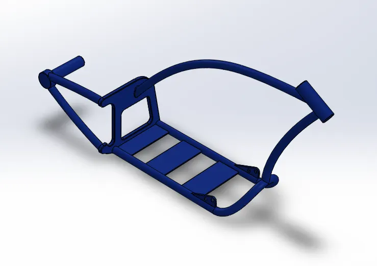
>> Chassis:
A chassis is the load-bearing framework of an artificial object, which structurally supports the object in its construction and function. An example of a chassis is a vehicle frame, the underpart of a motor vehicle, on which the body is mounted; if the running gear such as wheels and transmission, and sometimes even the driver's seat, are included, then the assembly is described as a rolling chassis.it is also known as the backbone of the Bike.
Features used
- Extrude
- Mirror
- Fillet
- Chamfer
- Dome
- Sweep
- Split
- Combine
- Revolve
Methodology
-First, add the blueprint sketch picture to the midplane.
-Then draw a curve on both the Bottom plane and the midplane and then use the projected curve tool to make a projected curve.
-After that draw, another sketch on the right plane and again using the projected curve make a curve.
-Now using the swept boss tool sweep a body through the curve and a sketch that is created by drawing on the midplane.
-Then using the mirror option make copies of the part concerning the midplane.
-After that create a sketch on the Right plane and then extrude it.
-Now draw a figure on the part that is created and then use the extrude cut option to remove some material from the part.
-After that, a small chamfer is given to one edge of the part and various fillets are given to some edges using the fillet tool.
-Then create a plane using a Reference geometry option and then draw a sketch of two concentric circles on the plane and also draw a curve on the midplane curve and then use the sweep tool to make a part.
-Using the split tool cut the part at the end.
-After that create another tool about the bottom plane and draw another sketch on it and also draw a curve on the midplane. After that using the sweep option makes a swept part.
-Then using the split option remove certain material from the part.
-After that combine all the parts that were created till now.
-Now draw another sketch on the midplane and using the revolve boss option create a revolved part.
-Again using the split tool remove some parts.
-Once more the combine tool is used and the whole parts are combined.
-Then sketch on the Midplane and is then extruded with the merge option turned on.
-After that various fillets are given.
-Now another sketch is drawn on the midplane and is then extruded to make a part.
-Then a split is given to remove some material.
-After that, some fillets are given, and using the mirror feature copy the part for fitting the kickstand and the brake lever on either side of the midplane.
-Now draw a sketch on the right plane and then is extruded and various filets are applied.
-Then a sketch is drawn on the surface of the part that is created above and is then cut extruded and then appearance is given to the whole part using the appearance tool.
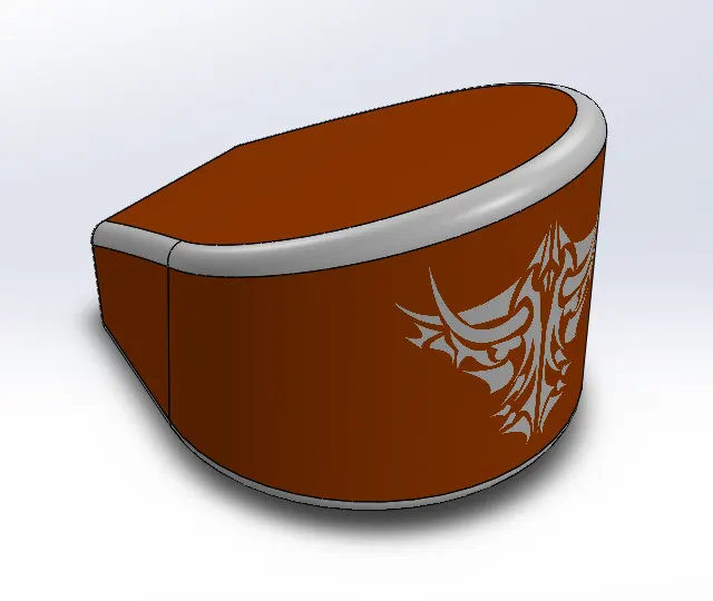
>> Oil Tank:
An oil tank is a safe container for flammable fluids. Though any storage tank for fuel may be so-called, the term is typically applied to part of an engine system in which the fuel is stored and propelled (fuel pump) or released (pressurized gas) into an engine. Fuel tanks range in size and complexity from the small plastic tank of a butane lighter to the multi-chambered cryogenic space shuttle eternal tank.
Features used
- Boss Extrude
- Combine
- Fillet
- Shell
Methodology
-First, draw a horizontal line on the Top Plane then draw two other lines from the ends of the first lines. After that draw a 3 point arc connecting the two lines.
-After that extrude the figure using Extruded Boss/Base tool.
-Now draw another sketch of a quadrilateral on the Midplane and then extrude that too with through all features turned on.
-Then using the combined tool combines both the extrusions to make a single piece.
-After that give fillets to the body using the fillet tool.
-Then as it is a tank, to give a hollowness use the shell tool.
-For changing the appearance of the body as well as the fillet use the appearance menu.
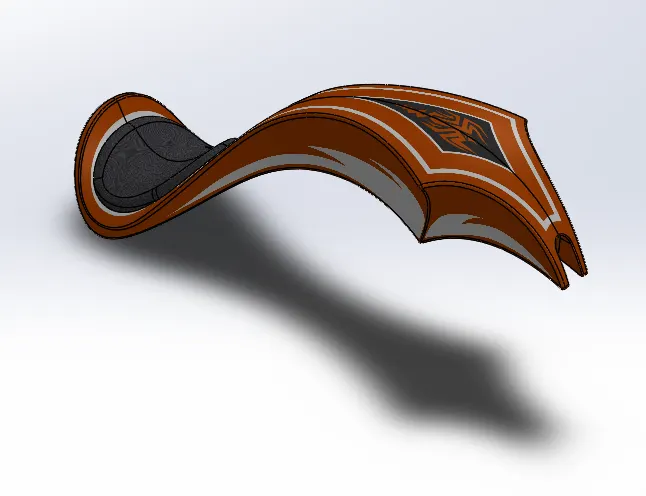
>> Gas Tank:
A gas tank (or petrol tank) is a protected container for flammable fluids. Though any storage tank for gasoline may additionally be so-called, the period is generally utilized to a section of an engine machine in which the gas is saved and propelled (fuel pump) or launched (pressurized gas) into an engine. Fuel tanks vary in measurement and complexity from the small plastic tank of a butane lighter to the multi-chambered cryogenic Space Shuttle exterior tank.
Features used
- Surface sweep
- Surface trim
- Projected curve
- Surface loft
- Split line
- Mirror
- Surface knit
- Fillet
- Shell
Methodology
-First, the Underlay image of the chopper is added to the midplane.
-Then a plane is created concerning the front plane.
-After that, a sketch is drawn on the newly created plane and the midplane and is used to create a swept surface using the Sweep Surface tool.
-Now another sketch is drawn on the Bottom plane and is used to trim certain material using the Surface Trim option.
-Then another plane is created concerning the Midplane and a sketch is drawn.
-Again make another plane and draw a sketch. Then draw another sketch on another plane that was created previously and using the two sketches make a projected curve.
-After that draw another sketch on the plane that was created previously and using the Surface Loft tool make a surface loft.
-Now make another plane concerning the front plane and draw a sketch. After that draw, another sketch on the Bottom plane, and these two sketches are used to create a projected curve.
-Then to make a boundary surface draw two sketches on the midplane and then use the Surface Boundary tool to make it.
-After that using the mirror tool make a mirrored version of the part on the other side of the midplane.
-Now using the surface knit option knit together all the surfaces.
-Then for making the seat sketch the Bottom plane and the split line option are used to combine with the gas tank body.
-After that using the surface extrude option the seat is generated.
-Later some fillets are given to the seats.
-Again the boundary surface is created for the seat.
-Now a surface loft is made at the bottom of the gas tank using the loft option from the surface window.
-Then again using the knit option knit together all the surfaces.
-After that, some fillets are applied.
-Now draw a sketch on the midplane as well as on the plane that was created with respect to the front plane and using the cut sweep option cut the part.
-Then again fillets are applied and the whole part is made into a shell.
-After that, appearances are given to the part and the seat separately.
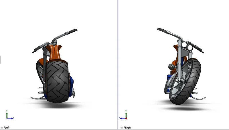
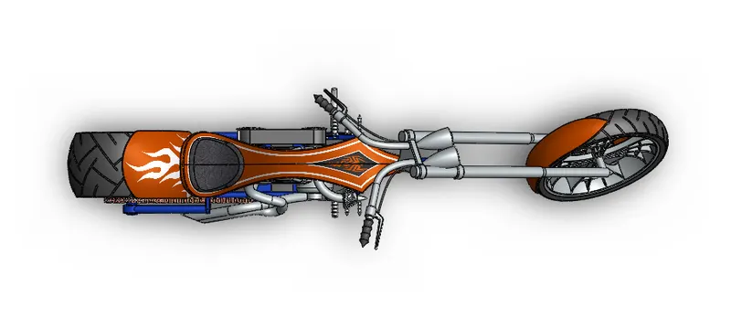
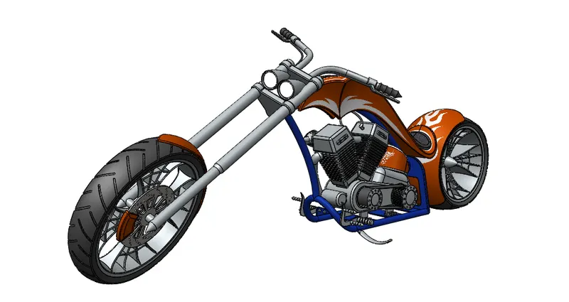
6. Assembled part/model of the bike:
- ISOMETRIC VIEW
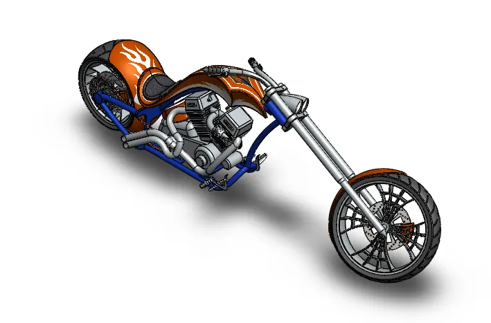
- FRONT VIEW
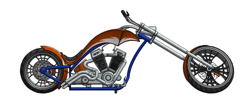
- SIDE VIEW (LSV & RSV)
- TOP VIEW
- CAMERA SETUP VIEW
7. Rendered Images of the bike:
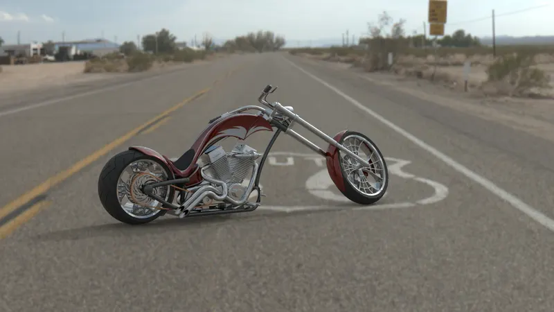
- ROUTE 66 (Image 01)
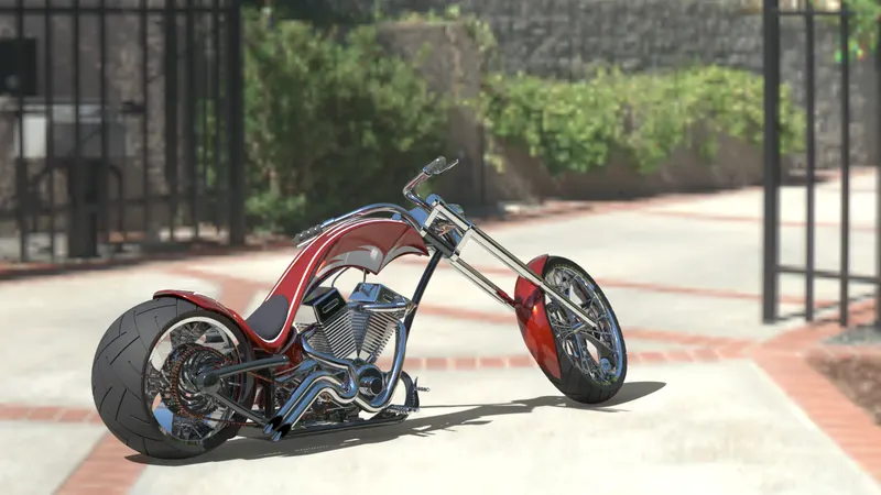
- Driveaway (Image 02)
8. Conclusion:
Thus The American Chopper has been designed, modeled, and assembled using solid works 2020, and photo realistically render using Solidworks visualize 2020.