Photo Realistic Rendering
AIM:
DESIGNING OF AMERICAN CHOPPER & ITS COMPONENTS WITH PHOTO-REALISTIC RENDERING USING SOLIDWORKS
OBJECTIVE:
Designing of an American chopper from scratch to final rendering of the model. This project helps to understand the tools in Solidworks by working on a real model.
INTRODUCTION:
American choppers are custom made bikes that attract attention solely to the premise of the theme itself. Customers used these bikes for promotional purposes at tradeshows or auction them off as a charity fundraiser. In this project, we built each component of an American chopper model and assembly it using Solidworks. As an automotive design engineer, I always wanted to build an entire vehicle by myself, with this project it happened.
MODELING OF AMERICAN CHOPPER:
This model has 13 individual parts which are:
- Transmission Belt
- Kick Stand
- Front Fender
- Rear Fender
- Oil Tank
- Pedal
- Chain
- Front Wheel
- Rear Wheel
- Front Fork
- Chassis
- Engine
- Gas Tank
Explaining each component:
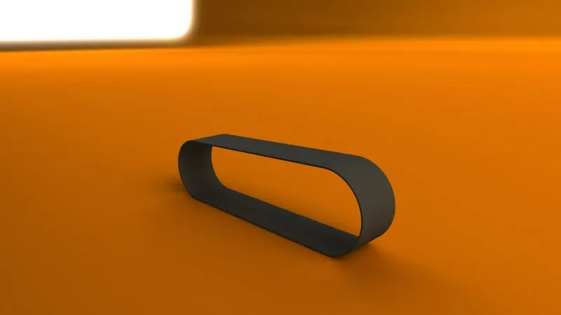
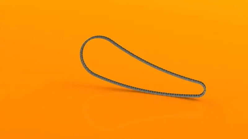
1. Transmission belt
A flexible material used to connect 2 rotating shafts mechanically. The transmission belt is used to connect the engine pulley with the transmission.
Procedure:
- Sketch of the transmission belt drawn on a front plane using line and 3 point arc.
- Offset the sketch inward for 3.5mm.
- Select the sketch and extrude.
- 1mm fillet given to the sharp edges.
- Appearance is given as matte rubber.
Result:
2. Kickstand
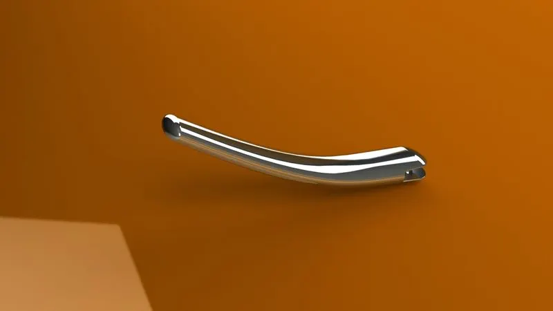
Kickstand is used to support the bike to the ground without leaning against another object. It is usually a piece of metal that flips down from the frame and makes contact with the ground.
Procedure:
- An ellipse is sketched on the top plane. On another plane, a spline is created to show the path for the ellipse to use the loft feature to make it into 3D.
- At the other end of spline, another reference plane is created.
- On that reference plane, an ellipse is drawn and loft feature is applied.
- On both ends, a dome feature is given to make it attractive.
- For the kickstand to rest on the floor the bottom surface should be flat so split feature is used to cut and consume some material.
- On the other end using cut extrude some material was removed for making the pivot. The pivot was made using boss extrude from the inner surface of the removed section.
- Fillets are given to the sharp edges.
- Appearance as given as chromium plate.
- The sketch is fully defined.
Result:
3. Front Fender
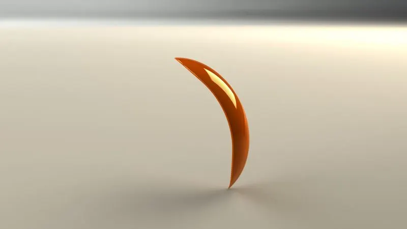
It is a part fitted in front above the wheel to prevent sand, mud, or other particles to throw into the air by the rotating tire.
Procedure:
- Using a 3 point arc the basic required shape of the fender is sketched. The sketch is offset to a distance to give a thickness to the fender.
- On another plane, the axis is sketched and revolved using the revolve base feature.
- Another sketch is drawn for removing an unwanted portion from the model and using the split feature the portion is removed.
- The sharp edges are filleted.
- Appropriate appearance is given to the model.
Result:
4. Rear Fender
It is a part fitted in the rear above the wheel to prevent sand, mud, or other particles to throw into the air by the rotating tire.
Procedure:
- Using a 3 point arc the basic required shape of the fender is sketched. The sketch is offset to a distance to give a thickness to the fender.
- Along the reference axis, the sketch is revolved using the revolve base feature.
- Another sketch is drawn for removing an unwanted portion from the model and using split feature the portion is removed.
- The sharp edges are filleted.
- Using shell feature
- Appropriate appearance is given to the model.
Result:

5. Oil Tank:
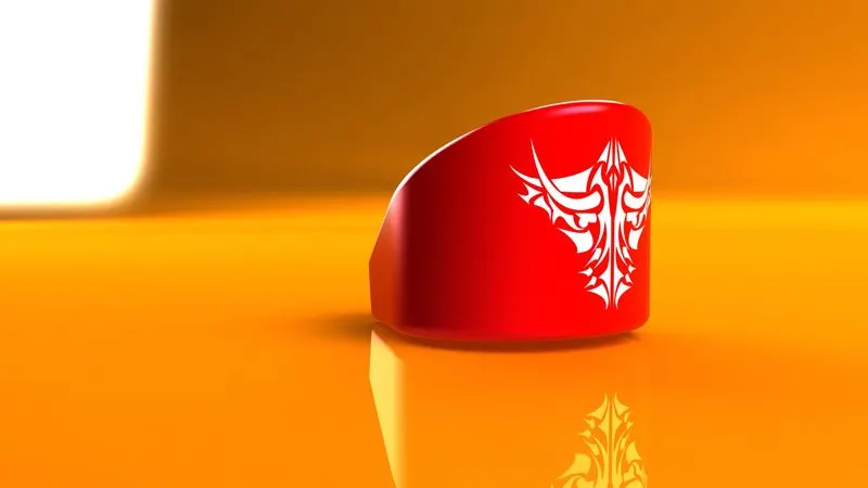
In American chopper, they have a separate oil tank for the engine which is located behind the engine.
Procedure:
- Using 2 sketches extruding 2 shapes.
- Using combine feature the common area is combined other area gets consumed/removed.
- The fillet is given to the sharp edges.
- Using the shell feature the material inside of the tank is removed.
Result:
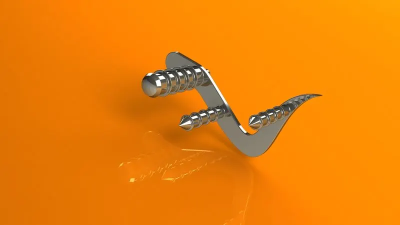
6. Pedal:
The foot pedal is attached to the chassis used for resting the foot and gear changing.
Procedure:
- Draw a sketch using spline and line features. Then give dimension to make it fully defined. Extrude it and apply fillet to the sharp edges.
- Use the dome circular feature.
- Apply linear pattern across the boss extrude. Use distance – distance chamfer at the end of 2 extrude.
- Give appearance as chrome to the art.
Result:
7. Chain:
The chain is used to transfer power from the transmission to the rear wheel.
Procedure:
- Sketch the path for the chain. Then sketch the chain links using circles and 3 point arc, trim the unwanted lines and make the chain links into a block so that it can be used again easily.
- The blocks are set on coincidence relation with the first sketch. Two blocks are in relation to concentric. Fillets are applied to the chain links.
- Using another sketch pins for the chain links are made and extruded.
- Using curve driven pattern pins and plates are attached to the curve as it looks good.
- Repeat the process over other curves to get the desired output.
Result:
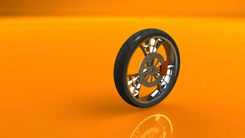
8. Front Wheel:
Front-wheel helps in the movement of vehicle. Front-wheel consists of an alloy wheel, tire, and brake assembly.
Procedure:
- First, the rim was sketched and revolved. Proper dimensions were applied.
- A spider web design is sketched in rim and using circular pattern 3 such shape is constructed.
- Proper fillets are added.
- Rotor was sketched and extruded. Design on the rotor was sketched and cut extruded. Using circular and linear patterns both the designs were created for the required number of instances.
- For designing the caliper required sketch was drawn and extruded. Chamfer was applied for the required dimension.
- Sketch of the tire is drawn and revolved.
- Using a cut extrude thread pattern was created. These threads was created for the whole tire using a circular pattern.
- Fillets were given to the thread.
- Appearance for the rim is chrome, for caliper we gave Siena and for tire matte rubber.
Result:
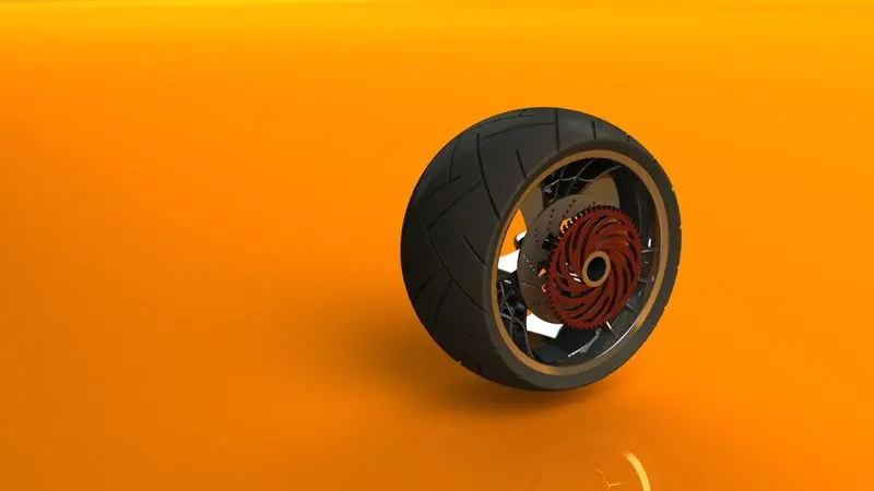
9. Rear Wheel:
Rear-wheel is located at the rear of the bike, it is rotated through the transfer of power from transmission through chain and sprocket. Rear-wheel consists of tire, caliper, rim, and sprocket.
Procedure:
- First, the rim was sketched and revolved. Proper dimensions were applied.
- A spider web design is sketched in rim and using circular pattern 3 such shape is constructed.
- Proper fillets are added.
- Rotor was sketched and extruded. Design on rotor was sketched and cut extruded. Using circular and linear patterns both the designs were created for the required number of instances.
- For designing the caliper required sketch was drawn and extruded. Chamfer was applied for the required dimension.
- Sketch for the sprocket was drawn and extruded. For the tooth in the sprocket new shape was cut extruded and chamfered to get the required sprocket.
- Pattern on the face of the sprocket was sketched and cut extruded. Using a circular pattern feature the shape on the face of the sprocket and the tooth design was created for the required number of instances.
- Sketch of the tire is drawn and revolved.
- Using a cut extrude thread pattern was created. This thread was created for the whole tire using a circular pattern.
- Fillets were given to the thread.
- Appearance for the rim is chrome, for caliper we gave Siena, for sprocket cast stainless steel, and for tire matte rubber.
Result:
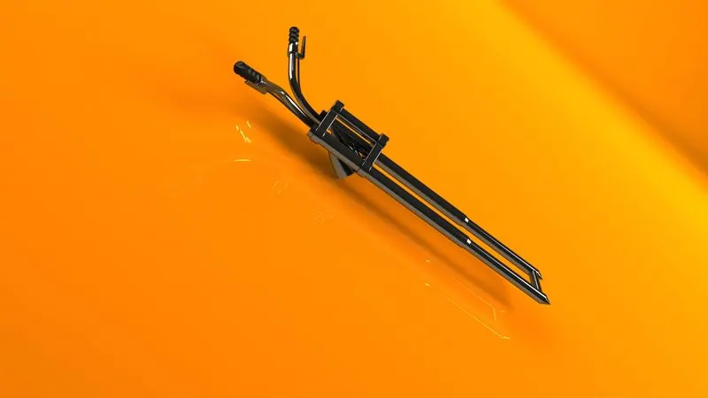
10. Front Fork:
A fork is a part of the chopper that holds the front wheel. Front fork consists of a shock absorber, which is held by a triple clamp. Above the triple clamp, the handlebar is fixed. The entire front fork helps to give direction to the bike. In between the triple clamp plates, we placed a headlight.
Procedure:
- Sketched the stem of the fork and using the revolve feature it is created.
- Sketch of the triple clamp is drawn on the top plane and extruded. Using the linear pattern feature another clamp was created at a distance from the first clamp.
- Axle was sketched and extruded at the bottom side of the fork.
- Using revolve feature the sketch of the headlight was revolved. To get into the required shape we use cut extrude and cut revolve feature. Then on the face of the headlight dome feature is given.
- Fillets are given to the sharp edges.
- Using body move/copy we copied the headlight and moved to a distance so that now there are two headlights.
- For the construction of the handle first we project a curve, so that in that path we can construct the handle. Normal to the curve we sketched a circle and sweep along the path.
- On the handle constructed a grip to hold using revolve. Clutch lever and brake pedal also sketched and extruded.
- For cable, another projected curve is created and a circle is created normal to the curve and a sweep feature is used.
- Select the bodies to mirror and combine all the bodies into a single body.
Result:
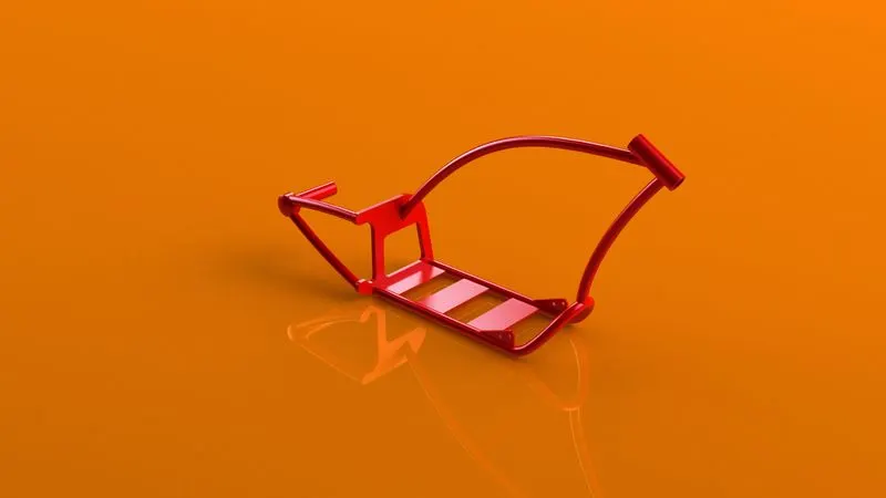
11. Chassis:
Chassis is the backbone of a vehicle. All the major components are fixed to the chassis. Chassis give the vehicle its strength and ability to handle well.
Procedure:
- Insert the blueprint of the chopper. Blueprint is used to get an idea of how the chassis should be.
- First we create the bottom tube of the chassis using a projected curve and sweep feature. Mirror the created tube with respect to the midplane.
- Sketch the frame on the rear end of the chassis and extrude it. Using cut extrude removed some parts from the center of the frame. Chamfer is used to cut some part at one end of the frame. Fillets are given to the sharp edges.
- A new plane is created at the vertex of the frame.
- Rear-end tubes are constructed on the newly created plane.
- Top and front tubes of the chassis are also made like the above tubes.
- Using split feature the joining of two tubes are trimmed perfectly.
- Fillets are given to the sharp edges.
- Appearance is given as Sienna.
Result:
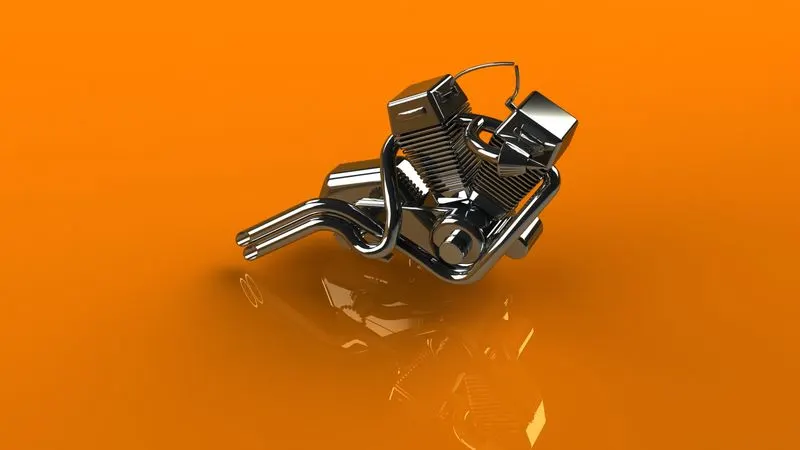
12. Engine:
Engine we designed is a 4stroke 2 cylinder. Engine is used to create mechanical energy so that it can be used for propulsion.
Procedure:
- Blueprint of the bike is added using insert sketch pictures option on the front plane.
- Referring to the blueprint shapes are sketched and extruded. Fillets are given to the sharp edges.
- A new plane is created in reference to the right plane and vertex. Then pulley for the transmission is created using a revolve feature.
- Using cut extrude making a circular cut on the face of the pulley and using circular pattern required number of circular cuts are formed.
- Using extrude and linear patterns the required sketch for cylinder is created.
- Draw a curve, sketch 2D diagram in two different plane by ensuring the end point should be same, use the feature like convert entities, construction line, spline after getting projected curve, draw two concentric circles, make use of pierce relation to curve then sweep it.
Result:
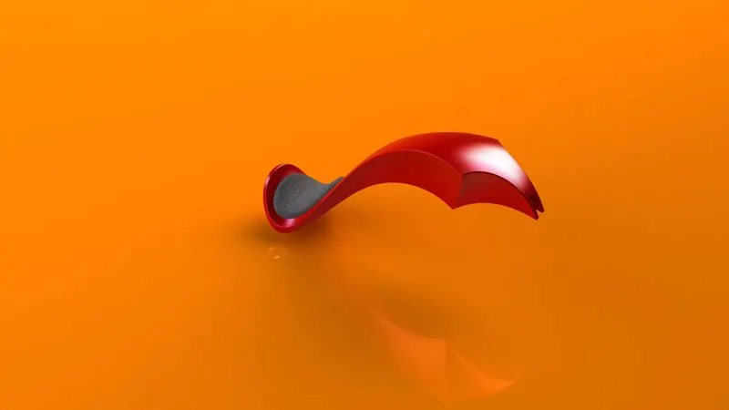
13. Gas Tank:
Gas tank is a storage tank that has the required fuel for the bike.
Procedure:
- Insert blueprint of the bike. Sketch roughly as per blueprint using splines, construction lines etc. Give dimensions and make it fully defined.
- Using surface sweep and loft features the surface of the gas tank is created.
- For making the 2D sketch to 3D projected curves are used. Also, boundary surface is used to make the face of the gas tank.
- Using a knit surface all the surfaces are combined and made into a single solid body.
- Fillets are given to the sharp edges.
- Using split line feature sketch of the seat is drawn and split from the top face of the tank. This portion is extruded and made into a seat. Fillets are given.
- Using cut sweep small portion from the bottom surface of the tank is removed for the chassis to easily fit.
- Since the whole part is made into solid using shell feature the inside of the tank is made empty.
Result:
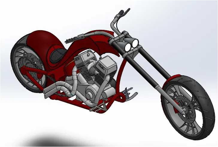
ASSEMBLY OF AMERICAN CHOPPER:
Procedure:
- All the parts which are designed in the part file are inserted into the assembly file.
- After that each component is given mates to fully define the model.
- Wheels and kickstand are snap to the floor.
Result:
2. Assembly
APPLYING DECALS, CAMERA SET-UP & SCENCES:
- Decals are applied to gas tank, oil tank and rear fender. We can use projected and label in mapping for applying the decals.
- Camera is inserted from view tab, inside view tab there is light and camera. Camera set-up helps in final rendering.
- Scenes: For making the model more realistic appropriate scenes are added.
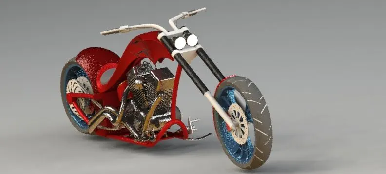
RENDERING:
We rendered the chopper using solidworks visualize tool. For rendering of individual parts we used render tools in solidworks.
Procedure:
- Import the assembly model to visualize.
- Change the appearance of model as you want.
- Add scenes to the model.
- Once satisfied final rendering is done.
Result:
CONCLUSION:
The project on design of American chopper with photo realistic rendering using solidworks has been created and completed successfully.