Photo Realistic Rendering
Objective:
The objective of this project is to know and understand the different tools and commands in SolidWorks.
To make a Model of different parts. To assemble the different parts in the assembly.
To Render and make realistic view in the SolidWorks PhotoView 360.
Part Modeling:
In part modelling first, sketch the Part and create the 3D Part with some 3D commands.
Parts Modeled for Chopper:
The following Parts of the Chopper are Modeled and assembled in SolidWorks.
- Transmission Belt
- Kick Stand
- Front Fender
- Rear Fender
- Oil Tank
- Chain
- Pedal
- Front Wheel
- Rear Wheel
- Front Fork
- Chassis
- Engine
- Gas Tank
- Transmission Belt
Features used to create a transmission belt:
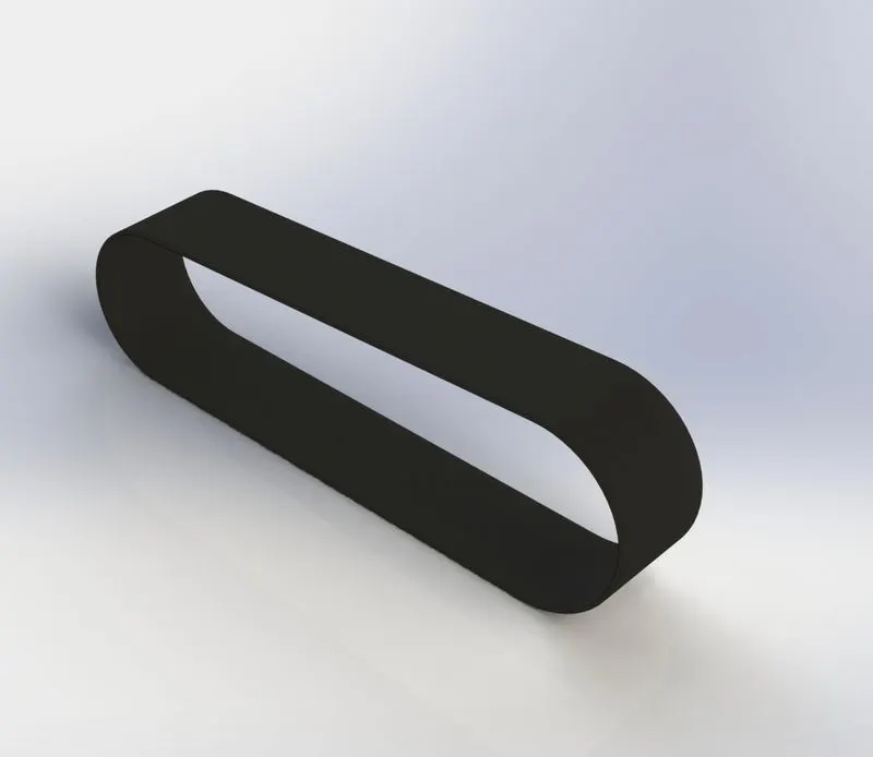
- Sketch
- Offset
- Extrude
- Fillet
- Appearances
The procedure to create a model of Transmission Belt:
- Open the SolidWorks Then, click on the new part to start modelling
- Before creating the sketch change the names of the planes.
- Front Plane - Front Plane Transmission Belt
- Top Plane - Top Plane Transmission Belt
- Right Plane - Right Plane Transmission Belt
- Then, select the front plane to start the sketch.
- The 20 sketch is created in the front plane by giving it dimensions, relations to fully define a sketch Wile scetching the offset command is used to duplicate the sketch to some distance
- After this process the sketch is closed. Then, the extrude command is used to conwert a 2D sketch into a 3D model.
- Then, the fillet is given to the belt as per the requirements. The model of the transmission belt is created.
- Kickstand
Features used to create KickStand:
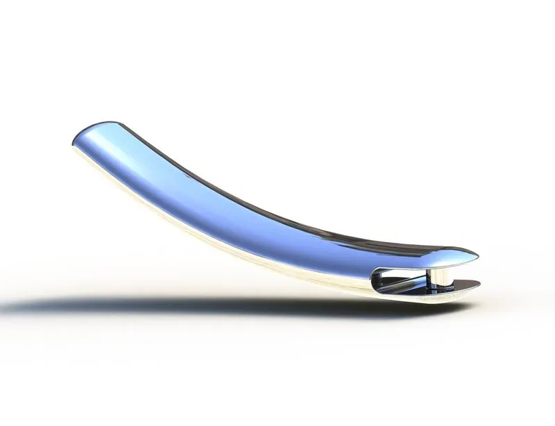
- Sketch
- Loft
- Dome
- Extrude Boss
- Extrude cut
- Fillet
- Split
- Appearances
Procedure to create a model of KickStand:
- Open the SolidWorks. Then, click on the new part to start modelling
- Before creating the sketch change the names of the planes.
- Front Plane - Front Plane
- Top Plane - Tap Plane
- Right Plane - Mid Plane
- Then, the mid-plane is selected to start the sketch,
- The 2D sketch is created in the front plane by giving it dimensions, relations to fully detined a sketch. While sketching we used the spline
- and trim commands
- There are two new planes created and the ellipse are drawn in the new plane as per the requirement.
- Then the loft command is used to create a lot for the kickstand.
- The extrude cut command is used to cut the parts which are not required for the stand.
- Front Fender:
Features used to create Front Fender:
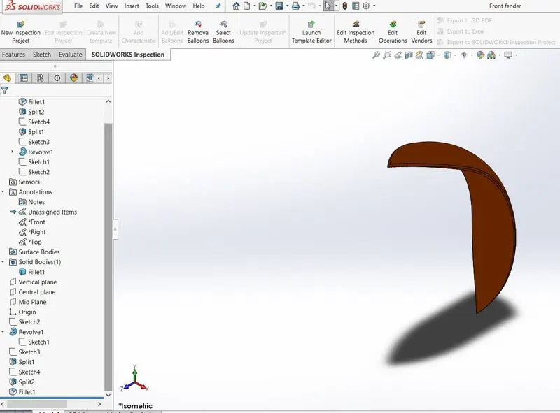
- Sketch
- Offset Entities
- Trim entities
- Revolve
- Dynamic mirror
- Split
- Appearances
- Trim entities:
- Select the trim type based on the entities you want to trim or extend. All trim types are available with 2D sketches and 2D sketches on 3D planes
- You can use any of the following trim options Power trim.
- Revolve- to create a revolve feature: Create a sketch that contains one or more profiles and a centerline, line, or edge to use as the axis around which the feature revolve can be used.
- Dynamic mirror is an important tool in SolidWorks. As you sketch the entities, they can be mirrored about the pre-selected sketch entity.
- Rear Fender
Features used to create Rear Fender:
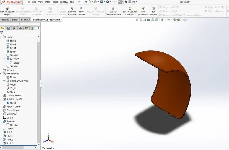
- Sketch
- Offset Entities
- Trim entities
- Revolve
- Appearances
Appearances
An Appearance defines the visual properties of a model inducing colour and texture. Appearances do not affect physical properties, which
are defined by materials. Every material is assigned to a delault appearance that emulates the look of the material
- Oil Tank:
Features used to create Oil Tank:
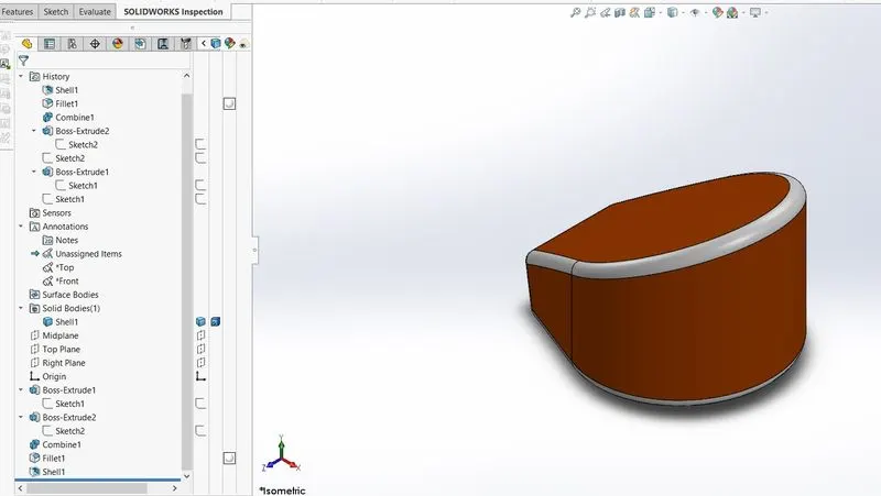
- Sketch
- Boss Extrude
- Combine
- Fillet
- Shell
- Appearances
Combine:
Combine feature is used to manually combine the two bodies into the one bady
Shell
The Shell Definition Property Manager is used to define the thickness of thin and thick shell elements.
- Chain:
Features used to create the Chain:
- Sketch
- Trim
- Fillet
- Blocks
- Extrude
- Pellens
- Appearances
- Blocks
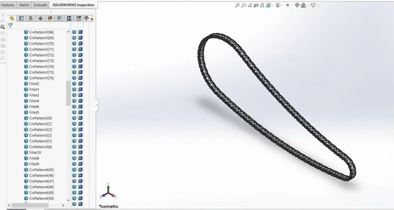
We can make, save, edit, and insert blocks for drawing items and sketch entities that We use often such as standard notes, title blocks, label positions, and many more. We can attach blocks to geometry or drawing vicws, and we can insert them into sheet formats
To create blocks:
1 Create a sketch
- Click Make Block (Blocks toolbar) or Tools > Block> Make...
3 Select the sketch entities you want to make as a block for Block Entities.
- Repeat steps 2-4 for each of the remaining sketch entities,
- With the sketch in coit mode, add the necessary relations.
- Pedal:
Features used to create Pedal:
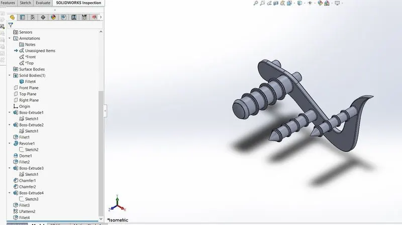
- Sketch
- Extrude
- Fillst
- Linear pattern
- Dome
- Chamfer
- Appearances
Chamfer
Chamfer is used to cut on the edge or corner of something that makes it slightly slope or rounded rather than being perfectly square or straight
Linear Pattern:
Linear pattern is also similar to the circular pattern. The features/bodies are pattemed linearly
- Front Wheel:
Features used to create the Front Wheel:
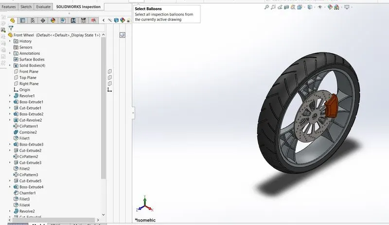
- Sketch
- Revolve
- Trim
- Filet Entities
- Boss/Base Extrude
- Revolve Cut
- Linear pattern
- Chamfer
- Fillet Features
- Cut Extrude
- Circular Pattem
- Appearances
Circular Pattem:
Circular pattern is used to create a pattern of the sporks and the patterns Grooves) available in the tyre. Also, it is used to create holes in thebrake discs of the front wheel. The parent bodies/features are used to create a different number of instances required to create the pattern circularly
- Rear Wheel:
Features used to create the Rear Wheel:
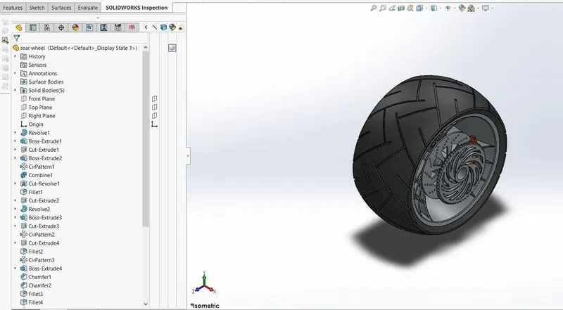
- Sketch
- Hevolve
- Trim
- Fillet Entities
- Boss/Base Extrude
- Planes
- Revalve Cut
- Linear pattern
- Chamfer
- Fillet Features
- Cut Extrude
- Circular Parten
- Appearances
- Front Fork
Features used to create the Front Fork:
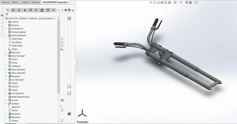
- Sketch
- Extrude
- Trim
- Revolve
- Split
- Plane
- Convert entities
- Move/copy Body
- Dome
- Mirror
- Combine
- Curve (Project Curve)
- Sweep
- Appearance
Move/copy Body:
Move/Copy body is used to move/copy the body from one place to other places in the fork.
Mirror:
By using the mirror feature we can mirror body or part to the other side. Mirroring bodies can be used whether in a single or multi-body part and
allows you to select solid geometry instead of the features and faces in a body. In the fork part, the one part of the fork is created and the other
part is mirrored. Then the parts are manually combined. It helped me to save a lot of time.
Project Curve:
Project curve is the kind of 3D curve which is projected based on the two different 2D sketches.
Sweep:
With the Sweep feature, we can create a shape by moving a 2D sketch Profile along a 2D or 3D sketch Path.
- Chassis:
Features used to create the Chassis:
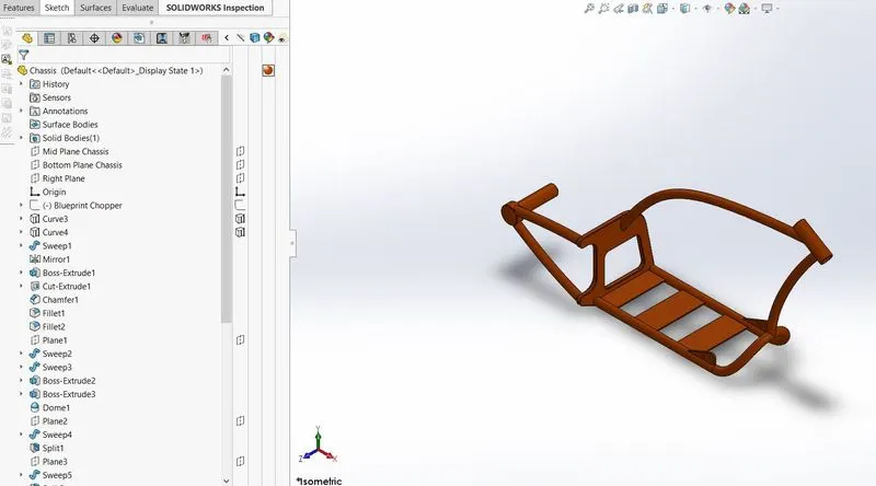
- Sketch
- Offset
- Convert entities
- Project Curve
- Trim
- Plane
- Sweep
- Split
- Revolve
- Cut Extrude
- Fillet
- Combine
- Appearance
- Engine:
Features used to create the Engine:
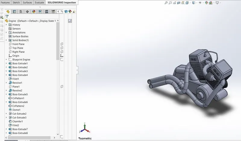
- Sketch
- Convert entities
- Trim
- Revolve
- Boss extrude
- Cut extrude
- Offset
- Dome
- Fillet
- Project curve
- Mirror
- Circular Pattern
- Split
- Gas Tank:
Features used to create the Gas Tank:
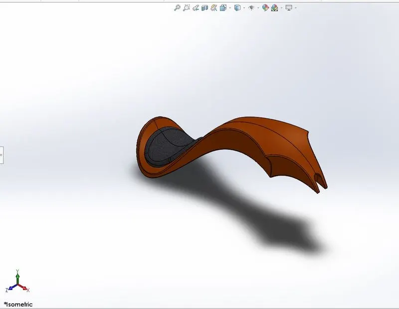
- Sketch
- Project curve
- Sweep Surface
- Loft Surface
- Fill surface
- Surface trim
- Surface knit
- Sweep cut
- Fillet
- Appearances
Loft Surface:
Loft Surfaces are surfaces generated by multiple 3D Curves or existing edges creating a smooth tangency between the selected curves.
Sweep Surfaces:
Sweep surfaces are surfaces that are generated from a section curve positioned along a path.
Filled Surface:
The Filled Surface feature constructs a surface patch with any number of sides, within a boundary defined by existing model edges, sketches, o curves, including composite curves.
Surface trim:
Primarily used to cut away material from a surface, and provides two modes: Standard and Mutual.
Surface knit
Surface knit is used to knit the two free edges/open edges of the surfaces together. It also reduces the gap between the two edges of the surface
Assembly of the Chopper
First, the Chassis part is inserted in the assembly by using insert parts in the option. After that the part is inserted in the assembly environment and clicked ok to fix the chassis.
After that, the other parts of the chopper are inserted into the assembly and given possible mate conditions.
Features used to assemble the Chopper:
- Mates
- Insert part
Mates:
Mates create geometric relationships between assembly components. As we add mates, we define the allowable directions of linear or
rotational motion of the components, we can move a component within its degrees of freedom, visualizing the assembly's behavior.
Rendering
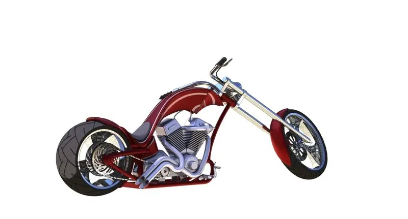
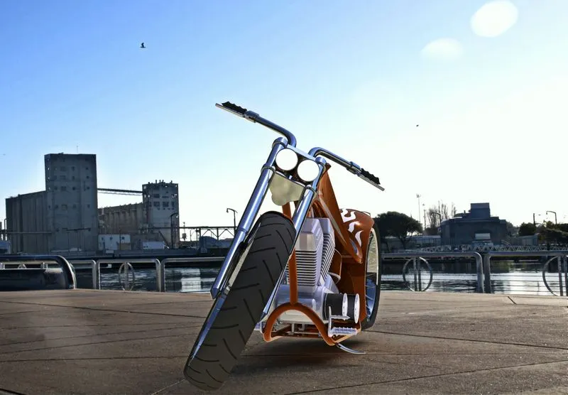
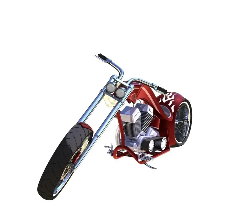
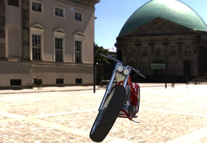
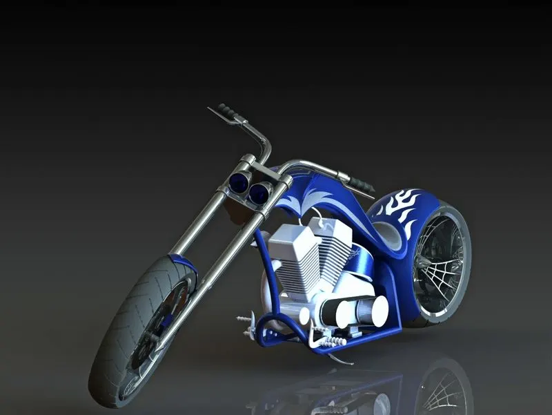
- Rendering is the process of creating realistic images of the Photorealistic model with the environment
- Rendering has been in SolidWorks.
Photoview 360
In the photorealistic model, some of the mate conditions and positions are changed to render realistic models.
- Then the photorealistic model is rendered into realistic images with different views
Conclusion:
- The parts of the chopper are sketched and modelled in the SolidWorks.
- The parts are inserted into the assembly environment and by applying the mates' chopper is assembled.
- The realistic image was rendered with the use of the 'Photoview 360