Photo Realistic Rendering
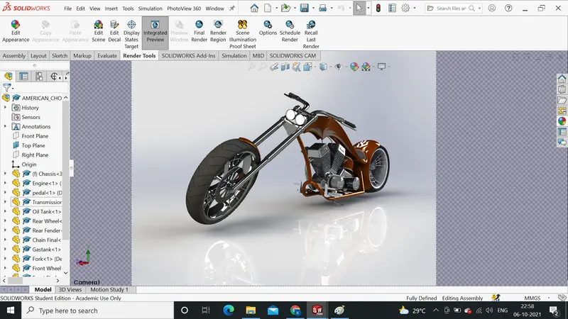
MODELING OF AMERICAN CHOPPER ON SOLIDWORKS
OBJECTIVE
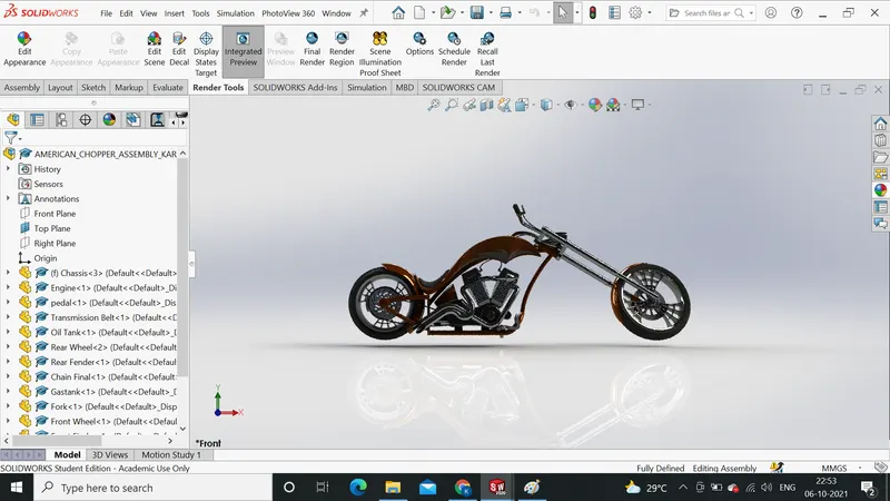
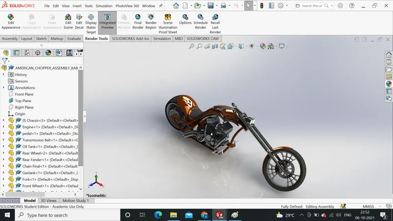
The objective of this project is used to create a model of different part of American chopper using Solidworks. Then assemble the chopper to insert the parts modelled component. To create a photorealistic model of the chopper and render the model using Solidworks visualize.
INTRODUCTION
Through this project I have been learn the designing of an american chopper on soildWorks and solidWorks visualise
There are different components is there
- Chassis
- Engine with exhaust system
- Front wheel and rear wheel with rims sprockets and caliper
- Front fork along with handlebar and grip
- Front and rear finder
- Oil tank
- Chain and Transmission belt
- Kickstand and foot pedal
After completing the project component, done the assembly and photo rendering of the chopper by using solidworks and solidworks visualize
DESIGN APPROACH
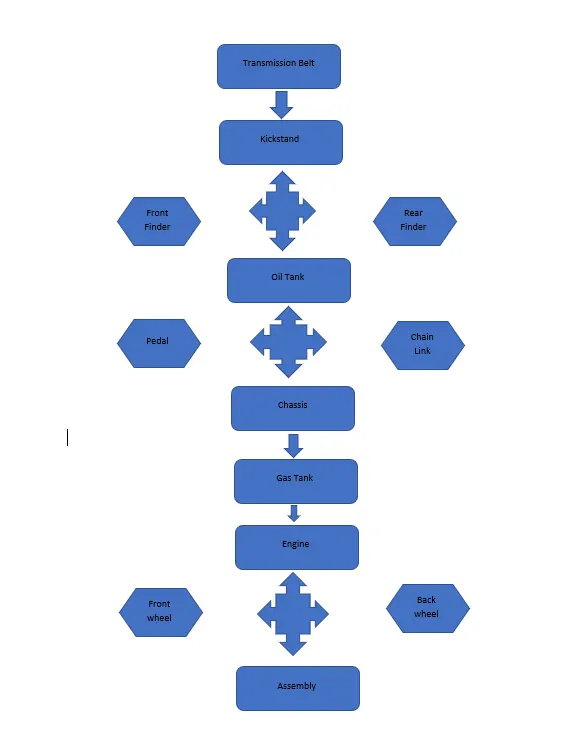
Starting with the transmission belt and ending with rendering section. It clearly described step by step by means of a flow chart
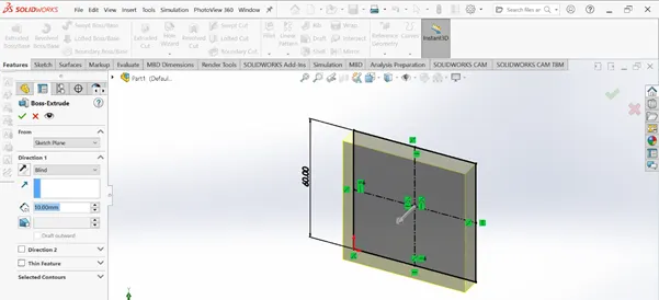
1.Extrude Boss:
One of the oldest commands in the SOLIDWORKS software is the boss/base extrude command. An Extruded Boss/Base feature will allow you to take a 2D sketch and add thickness to it in the third dimension.
Go to the toolbar and click Insert -> Boss/Base -> Extrude to pull up the Boss-Extrude Feature menu as well. Once the Extrude menu appears on the left-hand side of your screen, it will prompt you to select a plane or sketch that will be used to create a 3D model from.
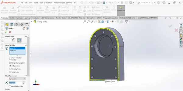
2.Fillet
Fillet/Round creates a rounded internal or external face on the part. You can fillet all edges of a face, selected sets of faces, selected edges, or edge loops

In Part 1 of our two-part series on the SOLIDWORKS Fillet command, we reviewed the details of the Constant Size Fillet tool. The remaining three types of fillet features: the Variable Size Fillet, the Face Fillet and the Full Round Fillet tools.
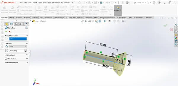
3.Revolved Bose Feature
In order to create a revolve in SOLIDWORKS, you need a sketch from which the revolve can be created as well as an axis for this sketch to be revolved around. The first thing to understand is what the sketch profile should look like in order to create a revolve.
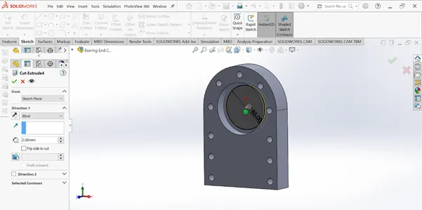
- Extrude Cut
Extruded cut feature removes material from the part. The End Condition, Draft, and Thin Feature options are same as described in Extruded Boss/Base
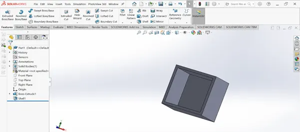
5.Shell
SolidWorks shell tool is mainly used for shelling process, in which the material removed from the inner body of model by keeping small thickness and results a hallow model
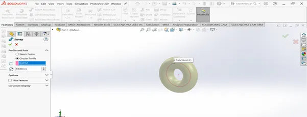
6.Sweep base/ Sweep Cut
Sweep creates a base, boss, cut, or surface by moving a profile (section) along a path, according to these rules: The profile must be closed for a base or boss sweep feature; the profile may be open or closed for a surface sweep feature.
7.Loft Bose/ Loft Cut
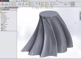
The loft feature is an important tool for (surface) modelling in SolidWorks. The loft feature creates a shape by making transitions between multiple profiles and guide curves. This tool is very valuable for modelling complex surfaces. You can do some cool stuff when you use this feature properly.
8.Linear Pattern
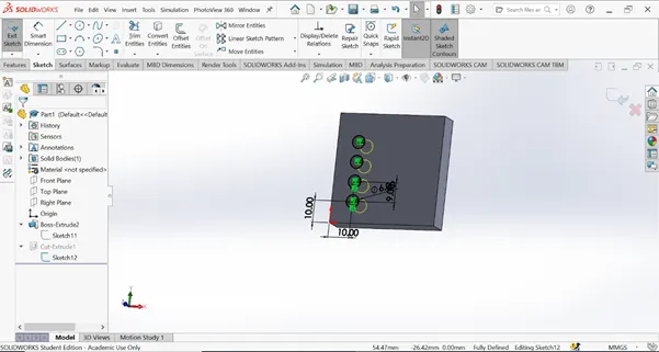
The Linear Pattern Command is used to drive features, faces, or bodies in a linear direction. This feature helps save time by cutting down the repetitive movements of adding a bunch of holes or other forms of geometry
9.Mirror
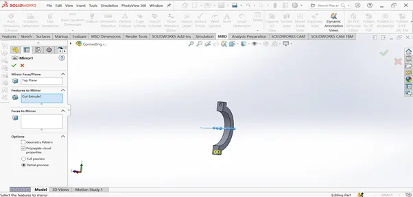
The Linear Pattern Command is used to drive features, faces, or bodies in a linear direction. This feature helps save time by cutting down the repetitive movements of adding a bunch of holes or other forms of geometry
10.Reference Geometry
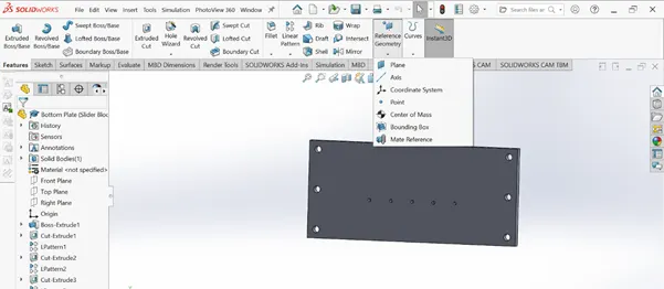
Reference geometry defines the shape or form of a surface or a solid. Reference geometry includes items such as planes, axes, coordinate systems, and points.
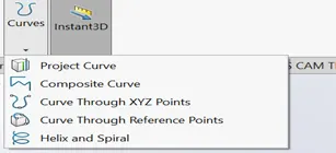
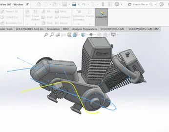
11.Projected Curve
- Mate
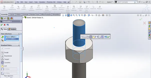
Mates create geometric relationships between assembly components. As you add mates, you define the allowable directions of linear or rotational motion of the components. You can move a component within its degrees of freedom, visualizing the assembly's behaviour.
Transmission Belt
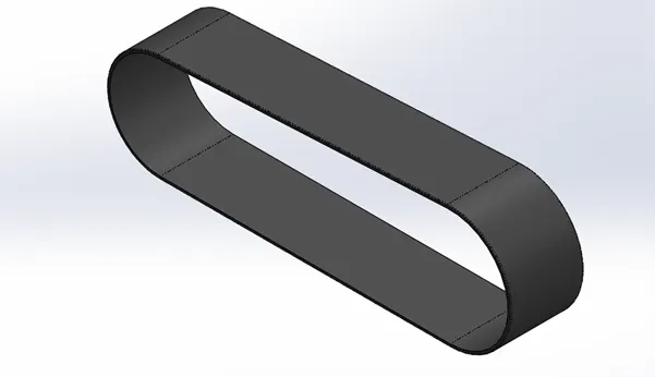
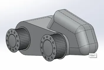
Transmission belt is a single extruded surface. The outer edge has been filleted with help of fillet option. The appearance used is a Matte rubber
Kickstand
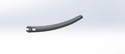
When designing the kickstand, according to the additional planes, I used the sketch drawings to create the loft parts using the sketches, applied the dome geometry on both sides, and used the other sketches to flatten the ground sill surfaces. To realize the shape, we also made an overhang cut for assembly. An extruded cylindrical boss is created, the cut parts are joined, and a fillet is applied to the joint of the cut edge and the boss.
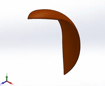
Front Fender
Again, the sketch was rotated using an axis. This is a single solid body designed on both sides using the Split Sketch tool. Fender's outer edge filleted.
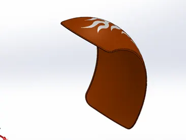
Rear Fender
The same method applies to the rear fenders as well as the front fenders, but the only difference between the two is the size of the two wheels depending on the size of the tires. Any part gives it a bright orange texture in metal coated sienna.
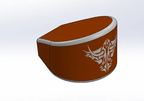
Oil Tank
The oil tank is sketched on the top plane and done a extruded base and now attain the structures of the oil tank A sketch is created again on the Midplane plane that has been extruded and combined , and at the end the part is created using the shell function to make hallow section. The corners are rounded by applying a fillet. Again in this case, the metal body is painted in the same Sienna color and the fillet edges are painted white.
Chain Link
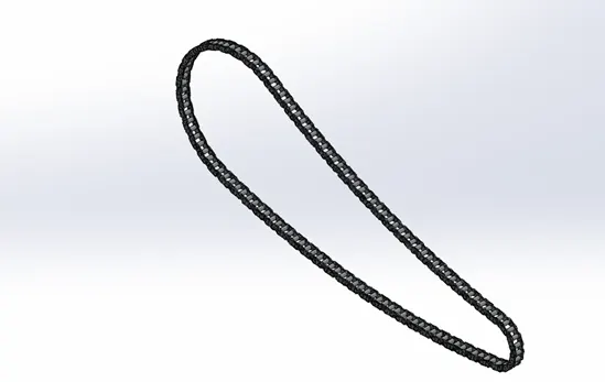
Now in this part, first outline the chain path with the help of arcs and lines, then create a front and back link, save it as a block diagram, and then apply the concentric relationship to a joint of the path at the same time, and then we calculate. We start with the arrangement process of a curved path from one path connection point to another path connection point, by determining the angle and the required number of blocks, until the entire cycle is completed, and finally, after sorting the arrangement, we reflect the link to the block On the pin. Relative to the mid-plane diagram. The appearance of the joint part adopts a finished chrome-plated metal plate.
Pedal
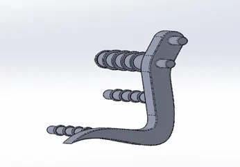
The design begins by sketching a sketch of the pedal foot on the front plane and an extrusion boss is made with round holes sized for the footrest and the pins are extruded a second time, now a sketch created on the upper plane for the leg rest then turned to create a 3D image. The top of the rest is applied domed and the edges and seams are smoothed to avoid sharp cuts, the front and rear extruded cylindrical parts are then chamfered to achieve a proper perfect finish and a circular pattern is extruded on each front extrusion line, then laid out using a linear pattern and the fillet is applied to all edges and seams of the final pattern.
The design of the two wheels is similar, the difference lies in the size of the wheels. First, create a revolved part on the right plane, namely the edge, now draw the spokes on the right plane and extrude, now merge with the hub to achieve the spider web design on the spokes, this is done using the spline tool in Draw a sketch on the surface of the radius, convert the entity and use appropriate construction geometry and reference mirrored parts, then cut and extrude the sketch, and then make a circular pattern along the edge of the rim to make three forks. Now we move it to a level and then squeeze it to design the disc or hub on the same plane. Now design on it and apply cutting extrusion. Now draw the caliper on the surface of the disc and squeeze it on both sides to chamfer to achieve the desired The appearance of the sprocket is chamfered. Now the sprocket is designed on the same plane with an extruded cylindrical hub. Now the pattern is used to draw on the surface of the sprocket and cut the applied extrusion, and then Model the entire sprocket, now make the final sketch and rotate the tire for the wheel, and draw the handle sketch on the tire. Use a three-point rectangle on the face, then cut, extrude and splice all the geometric figures to all sharp edges, and finally Reshape the design into a circular arrangement to form a realistic appearance, and apply the appearance body on different entities. The entire wheel consists of five solid parts: chrome-finished rims, Sienna metal paint brake calipers, chrome-plated sprockets and matte rubber tires.
Front Forks
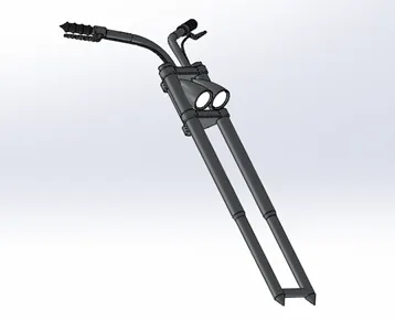
This part includes the front fork, handlebars, headlights, brake and clutch levers, ropes and grips. The fork design idea is to make one side of the fork or half of the fork then mirror along the face and make the cables and handles. The design begins with the rotation of a cylindrical fork along a straight plane, then on the face is outlined and extruded with mirrors and linear patterns, then with two extrusion cylinders to join the upper bridge and the face. mirror of fork. Another extrusion that is bent along the tip of the handle facing down is the headlight. To make it dig an extruded piece inside the face of the lighthouse. The edges of this section are finished to give the headlights a curved look. Finally, we focus on the handle being scanned using two curves used to form a projected curve and the like on the front of the handle, the scanning area is achieved using a rotate feature and inside the handlebars we draw the required geometry for the levers and extrude them into sharp, sharp edges, then a different expected curve appears. Designed to sweep the wires for the brake and clutch. form the desired 3D shape.
Chassis
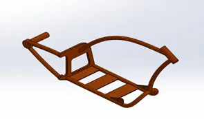
The chassis layout first draws two projection curves to get the curved path down the block, sweeps along the path, then mirrored to get the bottom geometry, sketch and extrude from the open end of the base and creates a part of Extrusion calculated to the desired shape, the bottom of the block chamfered, the sharp edges rounded both outside and inside. Two more scans were created and two more extrusion geometries were made. attachments to the sprocket, re-sweep the upper chassis lever from the front of the stopper and use a splitting tool to cut off excess material. Connect the chassis with the front fork to create a swivel at the front. The joint between the other two sweep rods is tightened, and now to connect with the pedal and the bracket, two extruded geometric shapes are created and the unwanted parts are squeezed out. Finally, all sharp edges are rounded as needed and a flat surface is added for further assembly.
Engine
It is a motor based design, a sketch is made in front and several bosses are created with the same sketch extrude and the proper shape is created. Then the top curved part is extrude and all the edges are filleted.
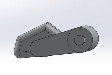
On the back of the motor, two rotating functions are created to support the distribution of the transmission belt, and the spokes use the same process on the opposite side of the extrusions created using a linear pattern and an extrusion around a circular area. Next, cut out the front side of the cylindrical extrudate to the desired shape
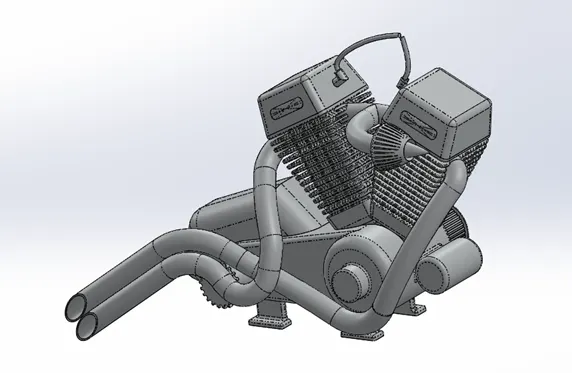
Sketch the back of the motor and the top of the case in order and extrude it to fit the whole body, then cut out a part from the engine body and create a straight pattern pin on the whole surface as shown in the figure increase. With figs. Fillets and chamfers are used. A sketch is created from above, and a spark plug is created in which the shape of the engine is now mirrored to the cylinder. The extrusion is then used to create the front gear for the chain link, cutting the ends of the 3D circular overhang according to design requirements, and creating four stands from the base of the engine hub for assembly purposes. engine. Design the engine exhaust pipe to create two more projected curves. Then, the following two curves are combined to form a composite curve. Dimensions The same process is performed on the second pipe, which is finally attached to the spark plug with two different sweeps of wire. The overall look given to the engine is chrome plate metal.
Gas Tank
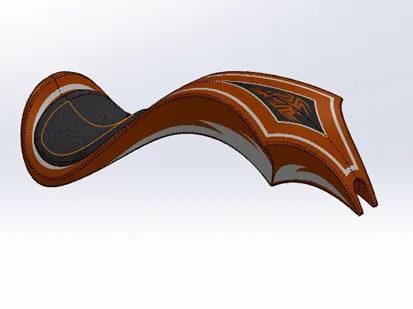
To start with, we need to know that all the features used in this part are in the polygon part of the model, we start by creating an additional reference plane and draw two sketches on it to make the basic layout of the fuel tank, now the edge is surface cut to achieve the design of the tank, an additional plane is added and a surface loft is created when the front face of the tank is now joined using the front and side boundary sweep with the rear of the fuel tank now reflecting the whole piece and knitting them together we get the complete tank structure kit, now on the back of the car we made a seat by extruding the surface and grinding the edges of the seat to create a rounded appearance with the surface. Attic and knitting tools we put a cover on the bottom of the tank, a sketch was drawn on the side of the tank to cut out the U for the assembly of the tank to the frame and then all the tips were smoothed out. the shell is created at the end to make it empty. Again a base sienna color was applied to the piece and a gray cotton material was used for the seats and decals used which are discussed when rendering the piece.
Assembly
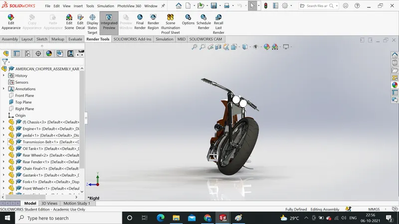
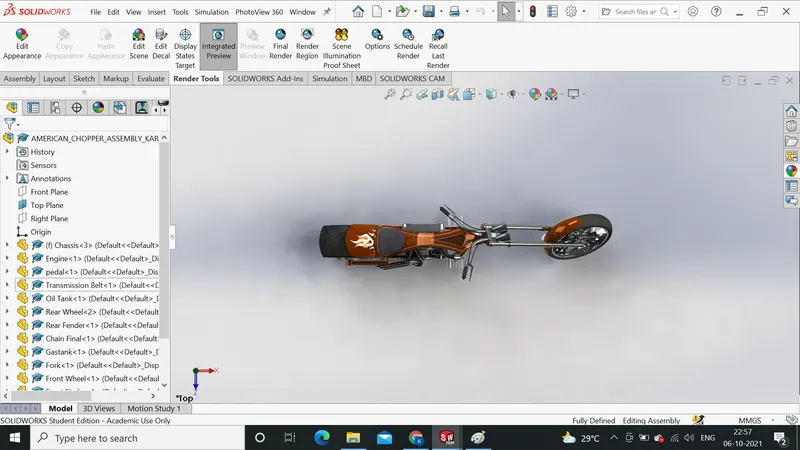
After fabricating all the parts, the most important part of assembling the whole cutter into one file will begin. To start, we started by introducing the chassis first and using its plane and geometry as the basis for the entire assembly, the second part we brought in was the engine, the engine base. assembled to coincide with the base of the frame then the planes of the motors are coupled so that it is a fixed and non-moving body finally a fuzzy gap is applied so that the part is fully defined , then we introduced the pedal pedal whose pins are matched to the holes in the frame and the Coincident Companion is formed to make the part fixed now since we need the pedals on both sides . with holes made in the frame and extrusions in the crutches to determine the angle of rotation from the crutches, an angled companion is provided with the body so there is no disturbance with the model, now we use straps The transmission is matched on the engine drivers to determine this completely with the companion, we provide an angle to do the matching with the pilots then we put the oil tank placed directly forward and entangled above the engine, now the rear wheel is concentrically entangled with the frame and axle of the wheel, the planes are matched accordingly and a Parallel coupling is applied to fully define the sketch , the rear fender is now applied above the rear wheel, now the chain link is done to initiate the wide relationship between the rear wheel sprocket and sprocket link parts and the engine, now the tank gasoline. secured with a long-distance mate and a frame-fit mate, the front fork is matched to the top of the frame and a width companion is applied to keep the vertical movement of the fork now for the steering angle of the chopper front part, a companion of The angle with certain restrictions applied to the fork and frame, finally the front wheel is fixed to the front fork as it is already fixed in case the rear wheel and fender are located above the front wheel as shown in the diagram.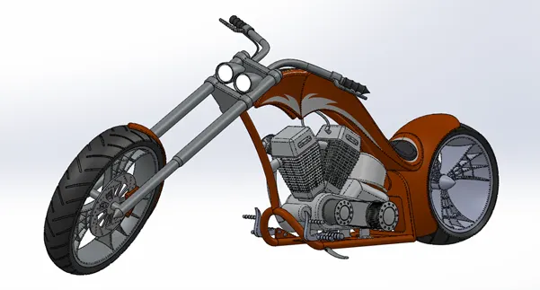
Rendering
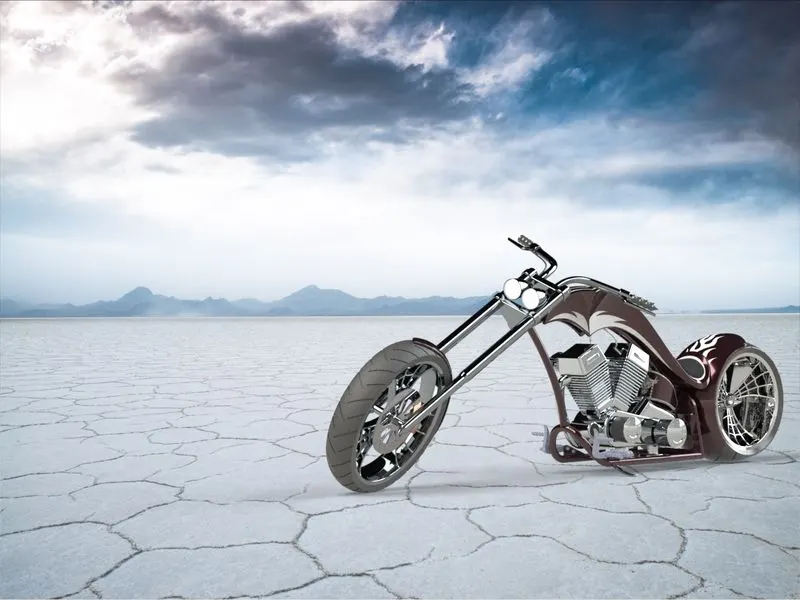
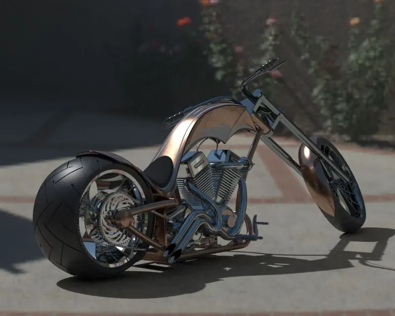
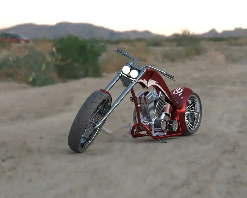
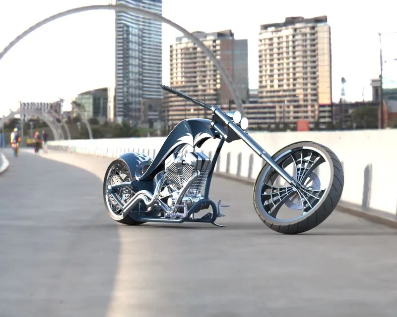
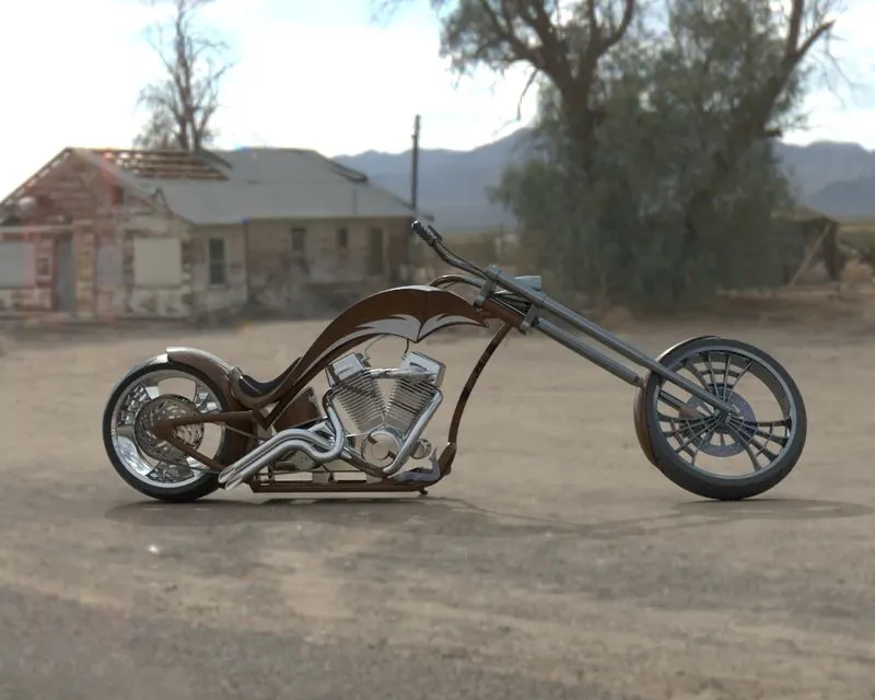
Since we've already explained how to render the model, the final step to making the bike look real is to start by checking the shapes added to all the parts to make it look as realistic as possible. Added decals to the face of the rear fenders and oil tank for a more refined look. Then I try to be more realistic than giving the camera view to set the desired light and the focal length to create the angle of view. Saves the camera angle to give the helicopter realistic field of view. Start the product more realistically by importing the following assembly file into a solidWork visualization, adding a background and changing the color of the product by adjusting the brightness, shadow density, gamma level according to the different requirements of different backgrounds. Create a model and see what background it suits you until you have an amazing product for your purpose
CONCLUSION
The part of the American chopper are modeled. Then inserted into the assembly environment and then chopper is assembled. The realistic image was rendered with the use of the Solidworks Visualize