Photo Realistic Rendering
AMERICAN CHOPPER
OBJECTIVE :
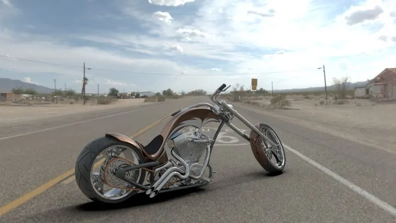
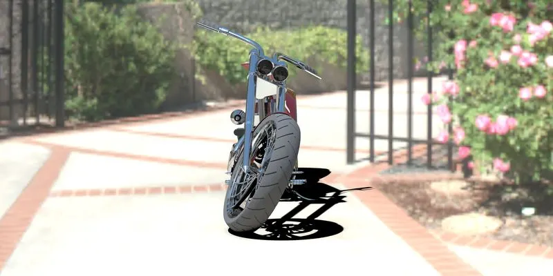
To model an American Chopper (Motor Cycle) using SolidWorks Part file, assemble all the individual parts using the SolidWorks Assembly file and perform appropriate rendering operations using PhotoView 360 and/or SolidWorks Visualize.
INTRODUCTION :
A Chopper is a type of custom motorcycle that emerged in California in the late 1950s.
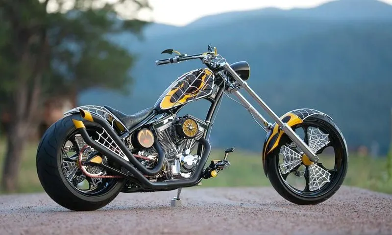
The chopper is perhaps the most extreme of all custom styles, often using radically modified steering angles and lengthened forks for a stretched-out appearance. They can be built from an original motorcycle that is modified ("chopped") or built from scratch.
Some of the characteristic features of choppers are long front ends with extended forks often coupled with an increased rake angle, hardtail frames (frames without rear suspension), very tall "ape hanger" or very short "drag" handlebars, lengthened or stretched frames, and larger than stock front wheels. The 'sissy bar', a set of tubes that connect the rear fender with the frame, and which are often extended several feet high, is a signature feature on many choppers.
Top-Down:
n top-down assembly design, one or more features of a part are defined by something in an assembly, such as a layout sketch or the geometry of another part. The design intent comes from the top, which is the assembly and moves down to the parts.
Button-down:
Bottom-up design is the traditional method. Your first design and model parts, then insert them into an assembly and use mates to position the parts. To change the parts, you must edit them individually. These changes are then seen in the assembly.
DESIGN METHODOLOGY :
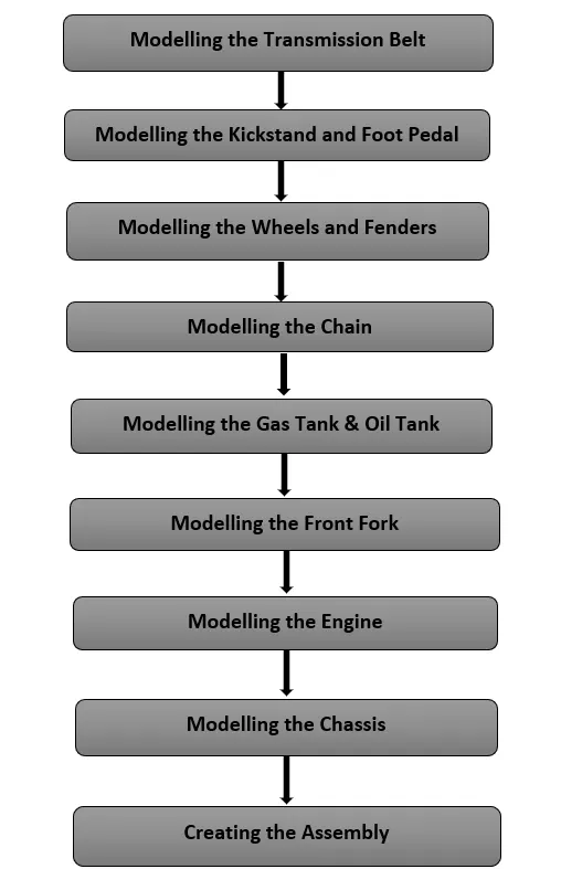
(I) PART MODELLING :
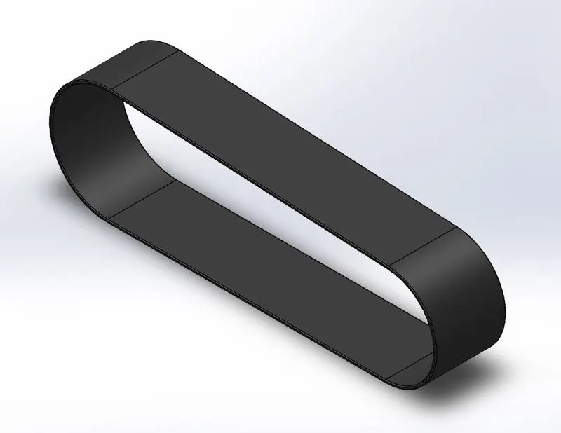
(1) Transmission Belt :
* The Extruded Boss/Base feature tool is used to create the 3D Belt out of the sketch.
* Matte Rubber is the type of appearance chosen here.
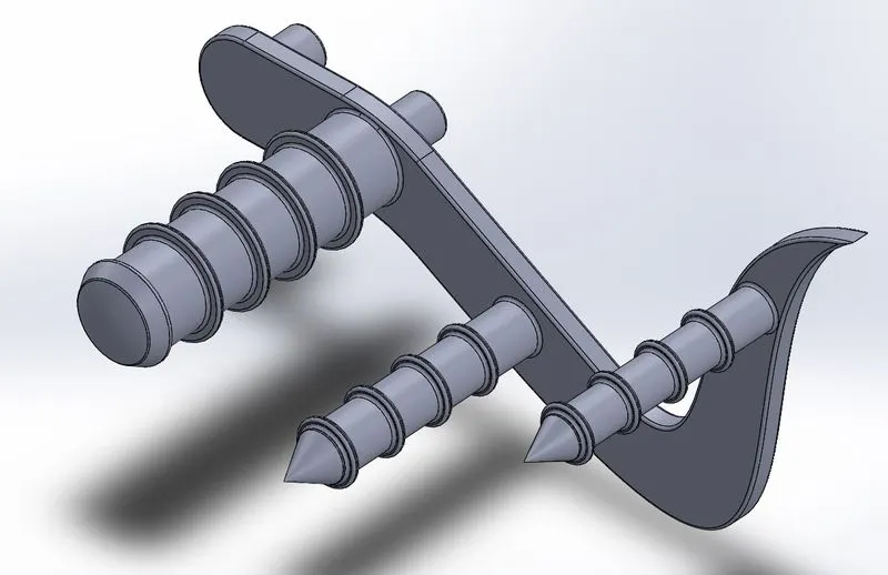
(2) Modelling the Kickstand and Foot Pedals :
* The Kickstand is modelled by using the Lofted Boss/Base between a couple of sketches, along with Revolved Boss/Base to create the pivot at the top. Some additional features such as Fillet, Dome, Split, etc were used, in order to enhance the aesthetic appeal of the part.
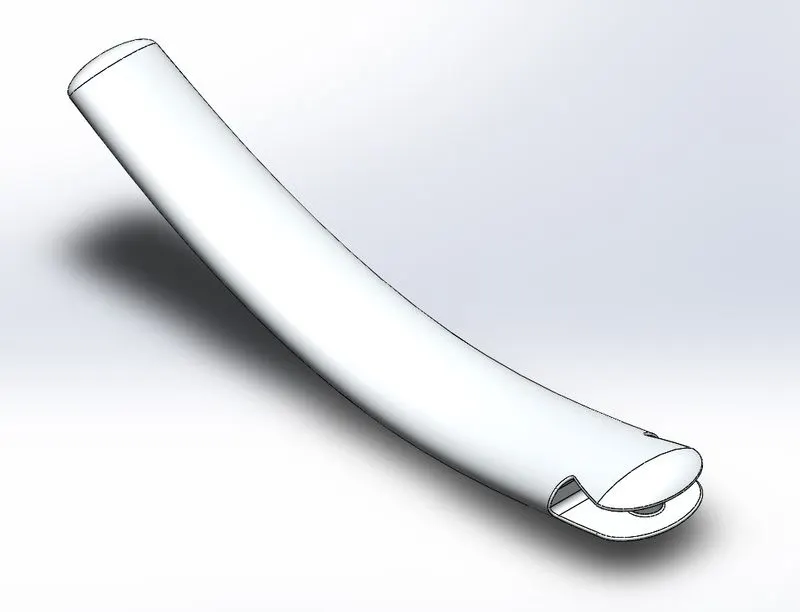
Similarly, the Foot Pedal is modelled using the Extruded Boss/Base, Revolved Boss/Base features. Here as well, the Dome, Fillet, Chamfer, etc features were used for a better outlook.
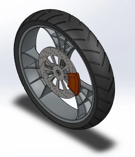
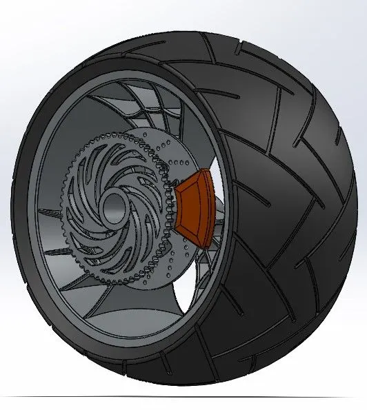
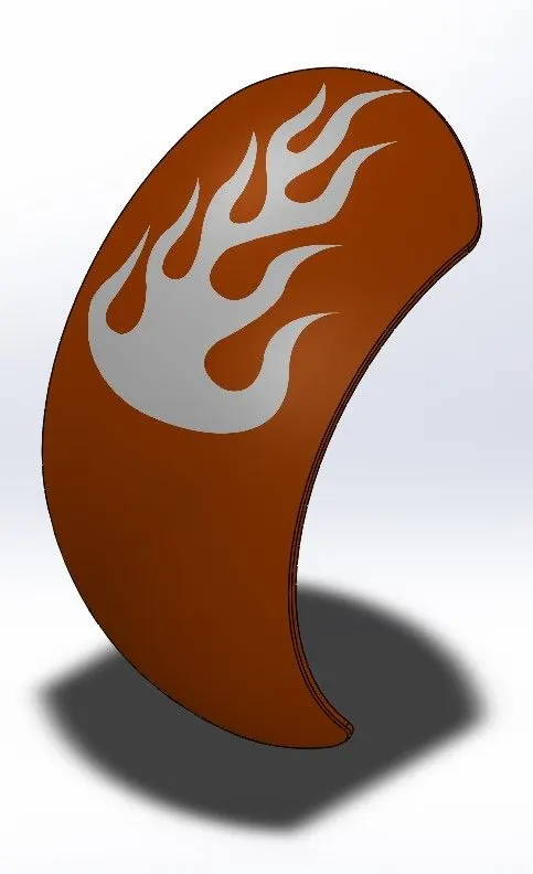
(3) Modelling the Wheels and Fenders :
* The Rear wheel is wider as compared to the Front wheel.
* Also, there's a Sprocket modelled along with the rear wheel for the chain drive.
* A number of features were used to model the wheels, such as Revolved Boss/Base, Extruded Boss/Base, Extruded Cut, Revolved Cut, Linear Pattern, Circular Pattern, etc.
* Fillet and Chamfer features were used to remove off sharp edges and improve the outlook.
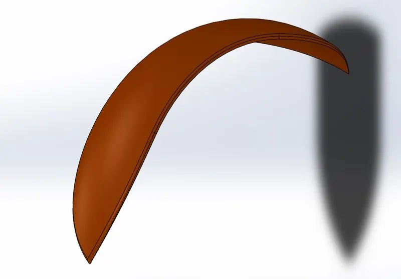
* Fenders or the mudguards were modelled simply by revolving the proper sketch around an appropriate axis.
* The features used here are Revolved Boss/Base, Shell, Fillet, etc
(4) Modelling the Chain :
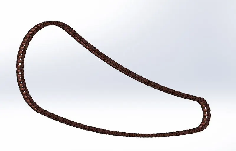
* The Chain is a part of the chain drive used for the transmission of mechanical power. The Chain is engaged with the sprocket present on the Rear wheel.
* Here, blocks were created out of the plates of the chain element.
* The features used here included Extruded Boss/Base, Fillet, etc.
* The plates were essentially repeated along a trajectory sketch created earlier out of splines and circular arcs. The Curve Driven Pattern was used at certain places along with the Mirror feature, to help ease the task and reduce the time involved.
(5) Modelling the Gas Tank & Oil Tank :
* The Oil tank was modelled simply by creating the outside geometry and then using the Shell feature to make it hollow. The Combine feature was used to give the appropriate shape to the Oil tank.
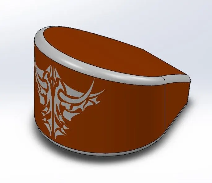
* The Gas tank is modelled by creating a bunch of appropriate surfaces first. For this, the commands in the Surface Modelling
tab were used. These surfaces were then stitched together with the help of the Knit Surface command.
* The different Surface modelling features used here are - Boundary Surface, Lofted Surface, Trim Surface, Swept Surface, etc.
* Fillet feature was used to enhance the aesthetic appeal as well as avoid any sharp edges of the tank.
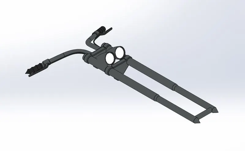
(6) Modelling the Front Fork :
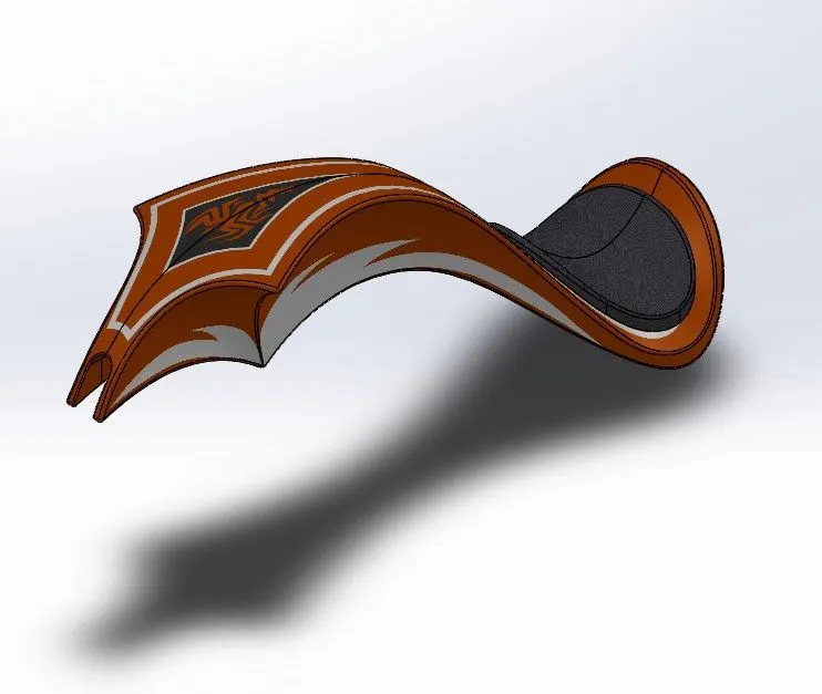
* The Fork is essentially a connecting link between the Front Wheel and the rest of the body.
* Here, Move Body, Project Curve are the features used in addition to the previously used features such as Extruded Boss/Base, Revolved Boss/Base, Combine, Swept Boss/Base, Mirror, etc.
(7) Modelling the Engine :
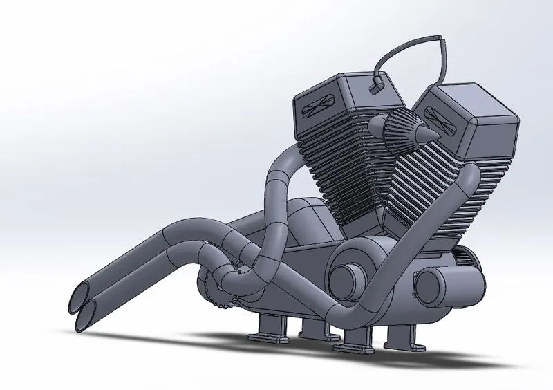
* The Engine modelled here is a V-twin engine. A V-twin engine, also called a V2 engine, is a two-cylinder piston engine where the cylinders share a common crankshaft and are arranged in a V configuration.
* To create the 3D curves that define the trajectory of a few of the parts, the Composite Curve option was used, which combines 2 Projected Curves together.
* The commands/features used here included Extruded Boss/Base, Revolved Boss/Base, Extruded Cut, Linear Pattern, Circular Pattern, Combine, etc. Also, Fillet, Chamfer, Dome features were used to avoid the sharp edges and enhance the aesthetic appeal.
(8) Modelling the Chassis :
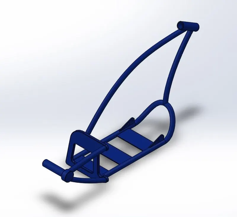
* The Chassis is nothing but the robust frame or central core structure of the motorcycle. The Chassis holds and locates all the parts of the motorcycle.
* The features used here are Extruded Boss/Base, Revolved Boss/Base, Swept Boss/Base, Extruded Cut, Combine, etc. along with Fillet, Chamfer, Dome.
(II) ASSEMBLY :
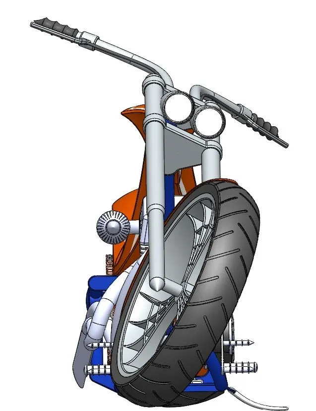
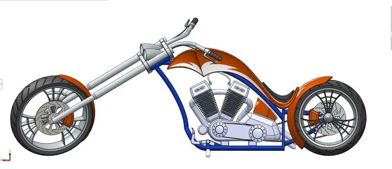
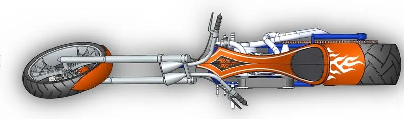
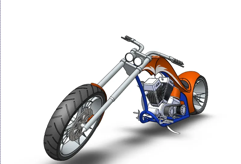
* All these individual parts are then assembled together using the SolidWorks Assembly file.
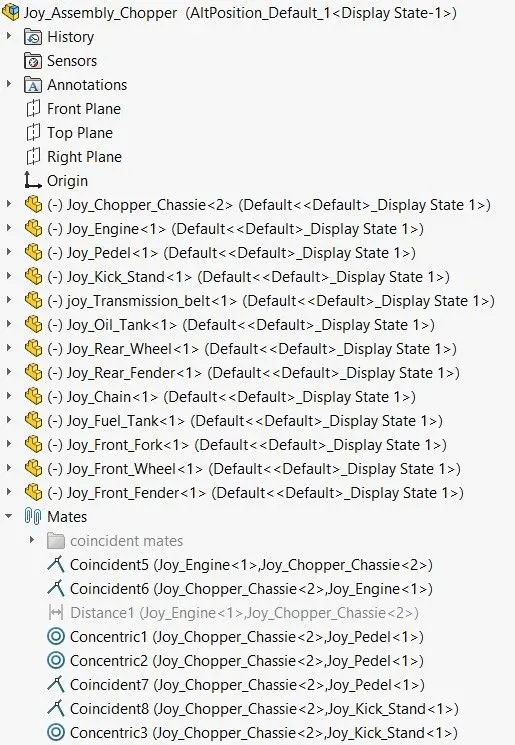
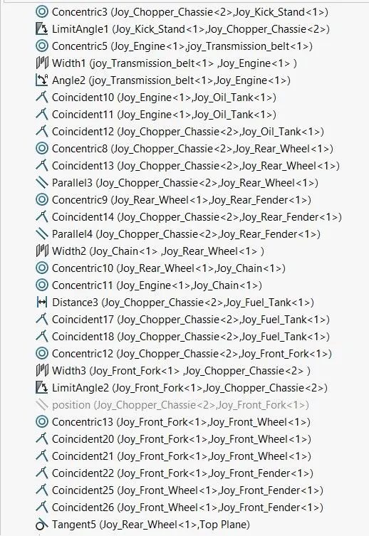
* Standard Mates such as Coincident, Tangent, Concentric, Parallel, etc are used to provide appropriate constraints. In addition to these, Advanced Mates such as Width to constrain few parts symmetrically.
* Also Angle constraints were used wherever required to provide rotational constraints, such as the Fork, Kickstand, etc.
Front View :
Side View (Right) :
Top View :
Camera View :
Assembly Feature tree:
 '
'

(III) RENDERING :
* Available Decals are added to enhance the outlook of a few of the parts.
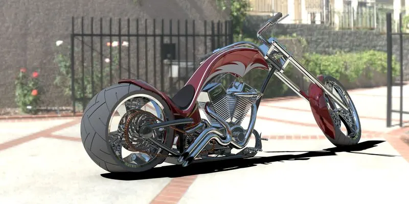
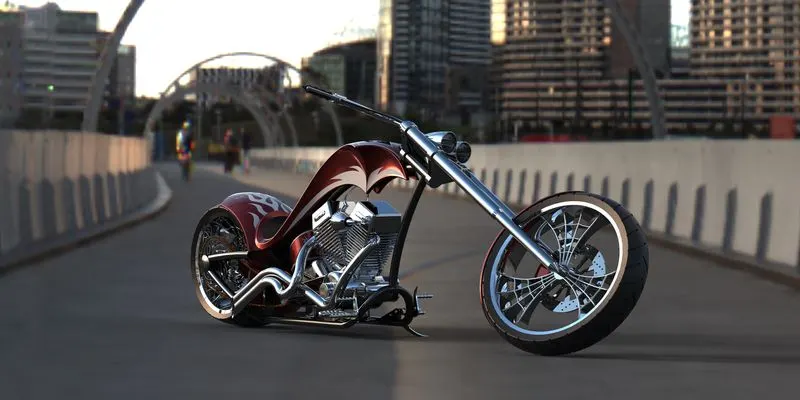
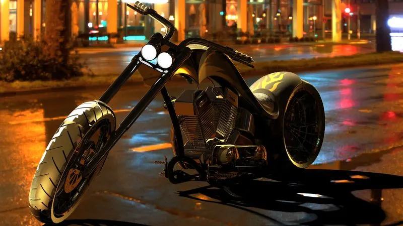
* The Copper Assembly is rendered using the Add-In Visualize tool provided by SolidWorks.
* Proper Scene is created for the rendering. An appropriate environment is set up for this purpose. Also, a suitable Backplate is chosen out of the library. The camera is set up by providing an appropriate location.
* The Perspective view is enabled to ensure a real-time look.
* Now, after providing suitable appearances the model is rendered.
CONCLUSION :
Thus, the complete exterior body parts of an American Chopper are modelled in SolidWorks Part file, assembled in SolidWorks Assembly file and then the assembly is rendered using SolidWorks Visualize.