Photo Realistic Rendering
MODELLING AND RENDERING OF AMERICAN CHOPPER USING SOLIDWORKS 2018
AND PHOTOVIEW 360
OBJECTIVE:-
- The main objective is to understand all the tools and features of Solidworks and Photoview 360.
- Design and development of individual 3D parts of the American Chopper.
- Integration of individual 3D parts to develop an assembly of the American Chopper.
- High-quality renderings of assembly and 3D parts.
INTRODUCTION:-
Solidworks is one of the most widely used software in the industry for the design and development of products. Solidworks performs a very important role in the Design Engineering cycle of the product where it gives basic visualization of a product by developing 2D sketches and 3D models. In this project, we’ve taken care of all the features and tools of Solidworks 2018 to develop an American Chopper.
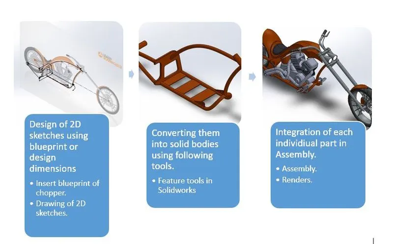
DESIGN METHODOLOGY:- Design methodology is explained considering the design approach for Chassis
- TRANSMISSION BELT:-
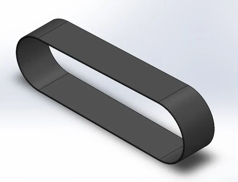
TOOLS USED:-
- SKETCH:-
The sketch is a two-dimensional representation of the product. These 2D sketches can be used to develop 3D part models. Sketch tools used:- Line, Circle, Spline, Arc, etc.
- EXTRUDE BOSS/BASE:-
The tool is used to convert fully defined and closed 2D sketches into 3D solid models. Extrude boss/base has various options and can be used according to the requirement.
- FILLET:-
This tool is used to get rid of sharp edges in the 3D model which creates curvature on the edges. The selection of lines and faces is available in various options. Sometimes this feature can also enhance the structural performance of the part.
- KICKSTAND:-
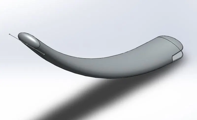
TOOLS USED:-
- SKETCH:-
The sketch is a two-dimensional representation of the product. These 2D sketches can be used to develop 3D part models. Sketch tools used:- Line, Circle, Spline, Arc, etc.
- REFERENCE PLANE:-
The reference plane which is normal to the sketch is created.
- LOFTED SURFACE:-
Solid is generated using two existing sketches along the tangent creating the smooth curve.
- EXTRUDE CUT:-
The material is removed to create the pattern for integration of kickstand to chassis.
- DOME:-
The tool provides a smooth curve on the face of the profile.
- SPLIT TOOL:-
This tool is used to remove unwanted surfaces/bodies when two or more bodies are intersecting each other.
- EXTRUDE BOSS/BASE:-
The tool is used to convert fully defined and closed 2D sketches into 3D solid models. Extrude boss/base has various options and can be used according to the requirement.
- FILLET:-
This tool is used to get rid of sharp edges in the 3D model which creates curvature on the edges. The selection of lines and faces is available in various options. Sometimes this feature can also enhance the structural performance of the part.
- PEDAL:-
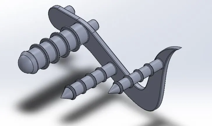
TOOLS USED:-
- SKETCH:-
The sketch is a two-dimensional representation of the product. These 2D sketches can be used to develop 3D part models. Sketch tools used:- Line, Circle, Spline, Arc, etc.
- EXTRUDE BOSS/BASE:-
The tool is used to convert fully defined and closed 2D sketches into 3D solid models. Extrude boss/base has various options and can be used according to the requirement.
- REVOLVED BOSS/BASE:-
This tool is used to extrude a 2D sketch into a 3D part along the circular path around the axis.
- DOME:-
The tool provides a smooth curve on the face of the profile.
- LINEAR PATTERN:-
This tool is used to pattern surfaces or bodies into one or two linear directions.
- FILLET:-
This tool is used to get rid of sharp edges in the 3D model which creates curvature on the edges. The selection of lines and faces is available in various options. Sometimes this feature can also enhance the structural performance of the part.
- CHAMFER:-
Creates a bevel feature along an edge, a chain of tangent edges, or vertex.
- FRONT FENDER:-
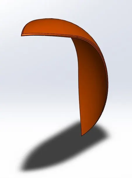
TOOLS USED:-
- REVOLVED BOSS/BASE:-
This tool is used to extrude a 2D sketch into a 3D part along the circular path around the axis.
- SPLIT TOOL:-
This tool is used to remove unwanted surfaces/bodies when two or more bodies are intersecting each other.
- FILLET:-
This tool is used to get rid of sharp edges in the 3D model which creates curvature on the edges. The selection of lines and faces is available in various options. Sometimes this feature can also enhance the structural performance of the part.
- SHELL:-
This tool is used to remove material from the solid body to create a thin-walled feature.
- REAR FENDER:-
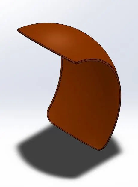
TOOLS USED:-
- REVOLVED BOSS/BASE:-
This tool is used to extrude a 2D sketch into a 3D part along the circular path around the axis.
- SPLIT TOOL:-
This tool is used to remove unwanted surfaces/bodies when two or more bodies are intersecting each other.
- FILLET:-
This tool is used to get rid of sharp edges in the 3D model which creates curvature on the edges. The selection of lines and faces is available in various options. Sometimes this feature can also enhance the structural performance of the part.
- SHELL:-
This tool is used to remove material from the solid body to create a thin-walled feature.
- OIL TANK:-
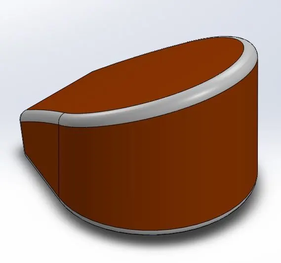
TOOLS USED:-
- SKETCH:-
The sketch is a two-dimensional representation of the product. These 2D sketches can be used to develop 3D part models. Sketch tools used:- Line, Circle, Spline, Arc, etc.
- EXTRUDE BOSS/BASE:-
The tool is used to convert fully defined and closed 2D sketches into 3D solid models. Extrude boss/base has various options and can be used according to the requirement.
- COMBINE:-
Combines two or more bodies. In this case, two sketches that are perpendicular to each other are extruded and combined to form a solid oil tank.
- SHELL:-
This tool is used to remove material from the solid body to create a thin-walled feature.
- CHAIN LINK:-
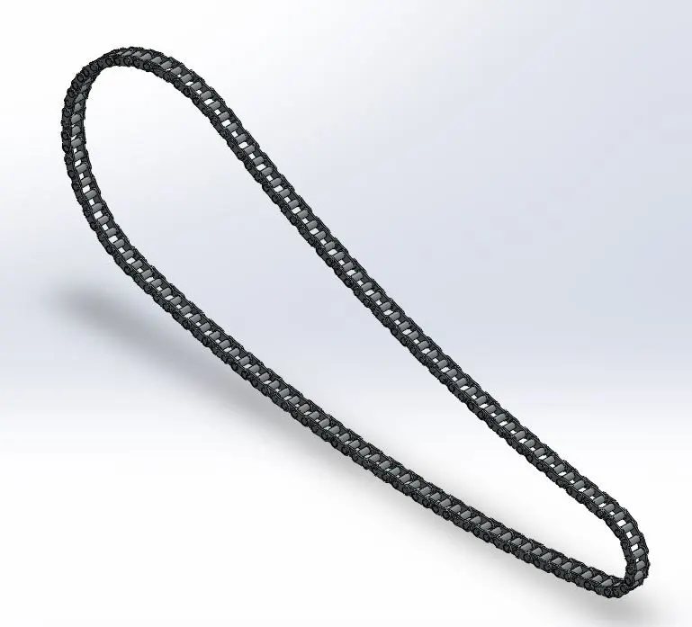
TOOLS USED:-
- SKETCH:-
The sketch is a two-dimensional representation of the product. These 2D sketches can be used to develop 3D part models. Sketch tools used:- Line, Circle, Spline, Arc, etc.
- SKETCH BLOCKS:-
This tool is used to make, save, edit and insert blocks of drawing items and sketch entities that we have to use often.
- EXTRUDE BOSS/BASE:-
The tool is used to convert fully defined and closed 2D sketches into 3D solid models. Extrude boss/base has various options and can be used according to the requirement.
- CURVE DRIVEN PATTERN:-
This tool is used to pattern faces, features, bodies based on a curve.
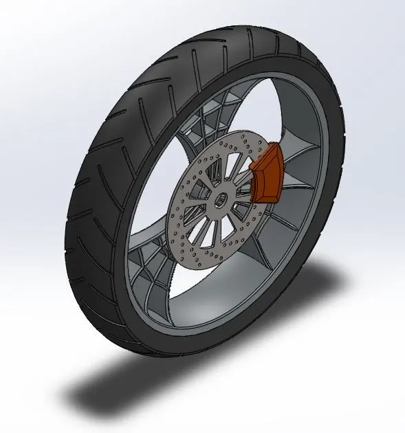
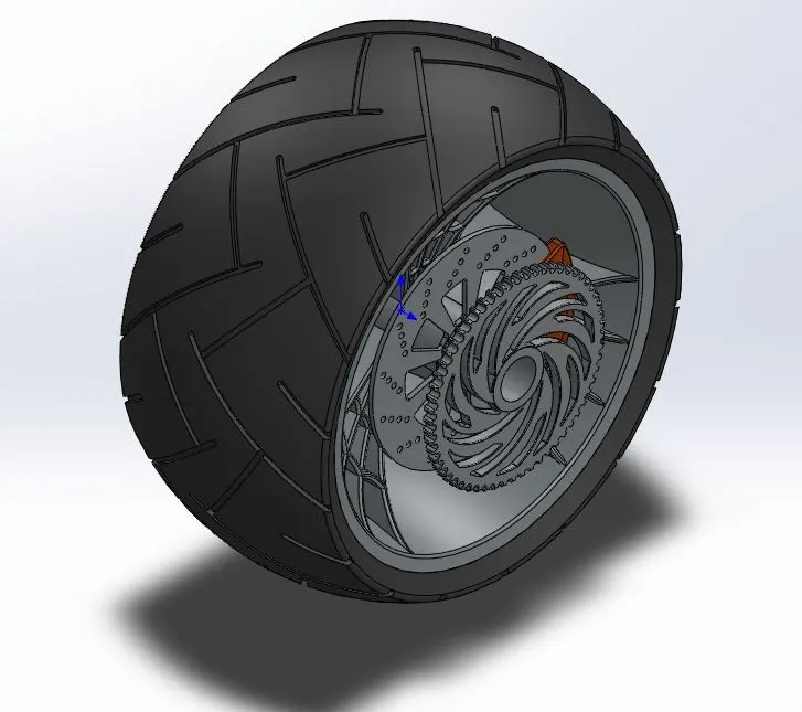
- FRONT AND REAR WHEEL:-
TOOLS USED:-
- REVOLVED BOSS/BASE:-
This tool is used to extrude a 2D sketch into a 3D part along the circular path around the axis. In this case, the sketch for the tire and rim is drawn in such a way that it can be revolved around the shaft.
- EXTRUDE BOSS/BASE:-
The tool is used to convert fully defined and closed 2D sketches into 3D solid models. Extrude boss/base has various options and can be used according to the requirement.
- EXTRUDE CUT:-
This tool is used to remove the unwanted material in the part model.
- CIRCULAR PATTERN:-
This tool is used to pattern surfaces, bodies, and features around an axis.
- FILLET:-
This tool is used to get rid of sharp edges in the 3D model which creates curvature on the edges. The selection of lines and faces is available in various options. Sometimes this feature can also enhance the structural performance of the part.
- CHAMFER:-
Creates a bevel feature along an edge, a chain of tangent edges, or vertex.
- APPEARANCES:-
This tool is used to apply appearances, scenes, and decals to surfaces, features, and bodies.
- CHASSIS:-

TOOLS USED:-
- SKETCH:-
The sketch is a two-dimensional representation of the product. These 2D sketches can be used to develop 3D part models. Sketch tools used:- Line, Circle, Spline, Arc, etc.
- Composite curves:-
This tool is used to construct a 3D curve using two or more 2D curves from different planes.
- SWEPT BOSS/BASE THIN USING CIRCULAR PROFILE:-
This tool is used to create a solid circular sweep body around an axis. In this case, the roll cage is designed using this tool.
- FILLET:-
This tool is used to get rid of sharp edges in the 3D model which creates curvature on the edges. The selection of lines and faces is available in various options. Sometimes this feature can also enhance the structural performance of the part.
- CHAMFER:-
Creates a bevel feature along an edge, a chain of tangent edges, or vertex.
- EXTRUDE BOSS/BASE:-
The tool is used to convert fully defined and closed 2D sketches into 3D solid models. Extrude boss/base has various options and can be used according to the requirement.
- EXTRUDE CUT:-
This tool is used to remove the unwanted material in the part model.
- APPEARANCES:-
This tool is used to apply appearances, scenes, and decals to surfaces, features, and bodies.
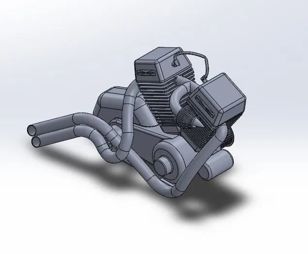
- ENGINE:-
TOOLS USED:-
- SKETCH:-
The sketch is a two-dimensional representation of the product. These 2D sketches can be used to develop 3D part models. Sketch tools used:- Line, Circle, Spline, Arc, etc.
- Composite curves:-
This tool is used to construct a 3D curve using two or more 2D curves from different planes.
- SWEPT BOSS/BASE THIN USING CIRCULAR PROFILE:-
This tool is used to create a solid circular sweep body around an axis. In this case, the exhaust pipe is designed using this tool.
- FILLET:-
This tool is used to get rid of sharp edges in the 3D model which creates curvature on the edges. The selection of lines and faces is available in various options. Sometimes this feature can also enhance the structural performance of the part.
- CHAMFER:-
Creates a bevel feature along an edge, a chain of tangent edges, or vertex.
- EXTRUDE BOSS/BASE:-
The tool is used to convert fully defined and closed 2D sketches into 3D solid models. Extrude boss/base has various options and can be used according to the requirement.
- EXTRUDE CUT:-
This tool is used to remove the unwanted material in the part model
- COMBINE:-
Combines two or more bodies. In this case, two sketches that are perpendicular to each other are extruded and combined to form a solid oil tank.
- CIRCULAR PATTERN:-
This tool is used to pattern surfaces, bodies, and features around an axis.
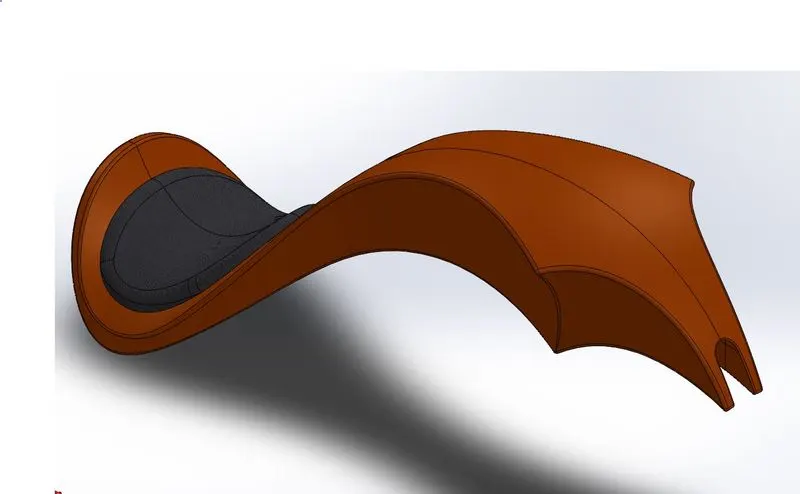
- GAS TANK:-
TOOLS USED:-
- COMPOSITE CURVES:-
This tool is used to construct a 3D curve using two or more 2D curves from different planes.
- BOUNDARY SURFACES:-
This tool is used to create a boundary surface between profiles in two directions.
- LOFTED SURFACE:-
This tool is used to create a lofted surface between two or more profiles.
- SURFACE EXTRUDE:-
This tool is used to create an extruded surface from the sketch.
- SURFACE KNIT:-
This tool is used to combine two or more adjacent, non-interesting surfaces together.
- SHELL:-
This tool is used to remove material from the solid body to create a thin-walled feature.
- DYNAMIC MIRROR:-
This tool is used to mirror entities dynamically.
- FRONT FORK:-
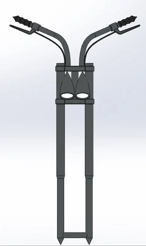
TOOLS USED:-
- Composite curves:-
This tool is used to construct a 3D curve using two or more 2D curves from different planes.
- SWEPT SURFACE:-
This tool is used to create a surface by sweeping an open or closed profile along an open or closed path.
- DOME:-
The tool provides a smooth curve on the face of the profile.
- LINEAR PATTERN:-
This tool is used to pattern surfaces or bodies into one or two linear directions.
- REVOLVED BOSS/BASE:
This tool is used to extrude a 2D sketch into a 3D part along the circular path around the axis. In this case, the sketch for the tire and rim is drawn in such a way that it can be revolved around the shaft.
- EXTRUDE BOSS/BASE:-
The tool is used to convert fully defined and closed 2D sketches into 3D solid models. Extrude boss/base has various options and can be used according to the requirement.
- EXTRUDE CUT:-
This tool is used to remove the unwanted material in the part model.
- COMBINE:-
Combines two or more bodies. In this case, two sketches that are perpendicular to each other are extruded and combined to form a solid oil tank.
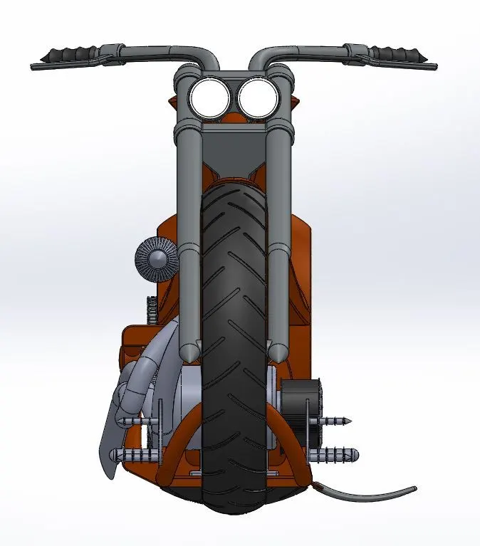
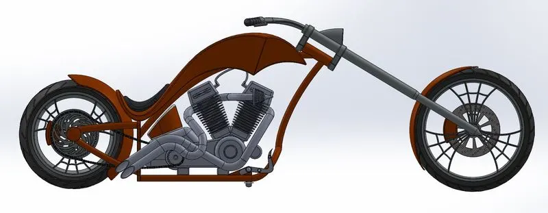
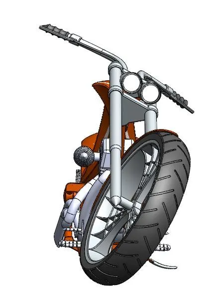
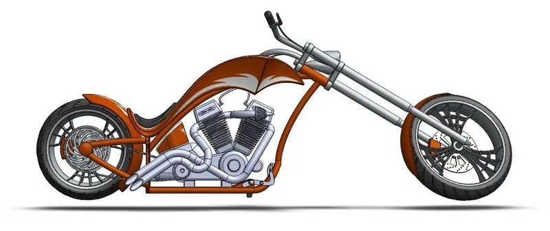
- SCREENSHOTS OF ASSEMBLED MODEL.
SIDE VIEW
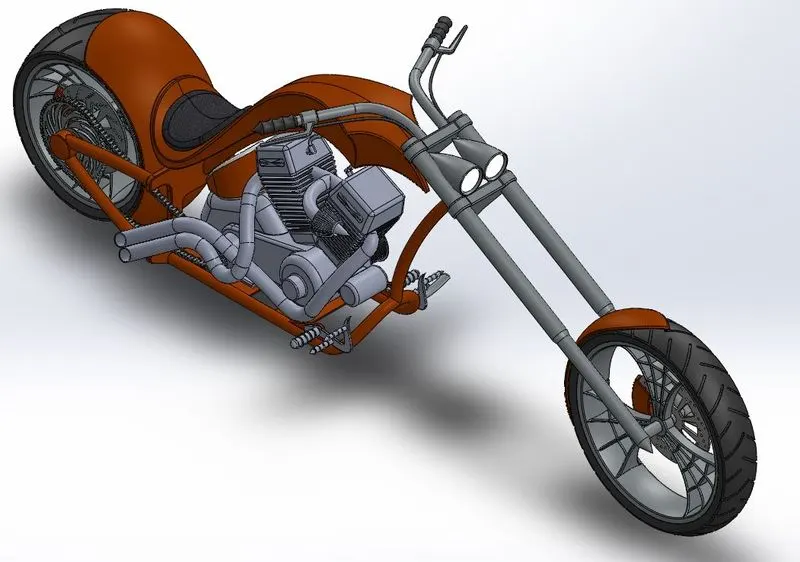
ISOMETRIC VIEW
FRONT VIEW
- RENDERINGS:-
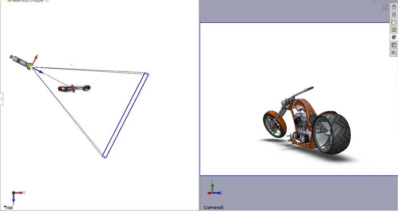
CAMERA AND BACKGROUND SCENE SETUP
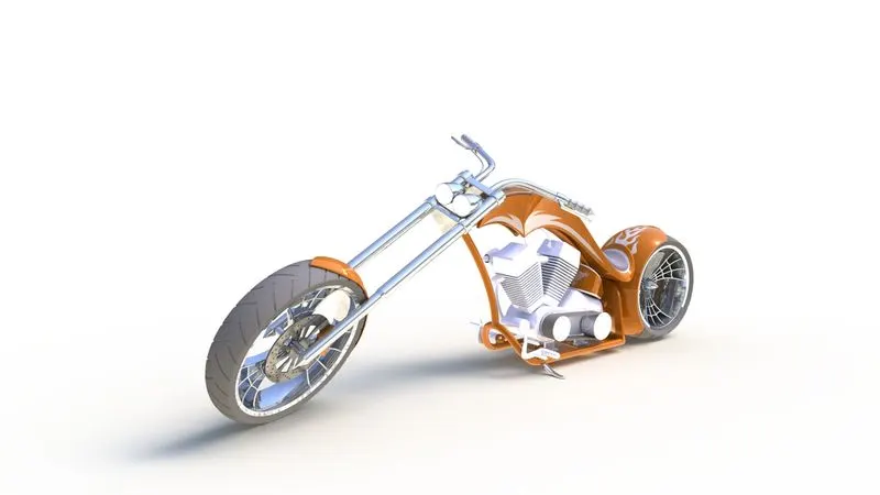
RENDER WITH CAMERA SETUP1
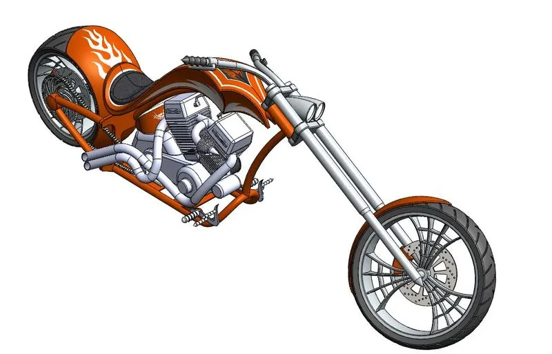
RENDER SETUP ISOMETRIC VIEW
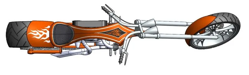
RENDER SETUP TOP VIEW
RENDER SETUP SIDE VIEW
RENDER SETUP FRONT VIEW