Design and Solid Modelling of Chopper Bike using Solidworks
Project Name:
Designing and rendering of American Chopper using SolidWorks.
Objectives:
The main objective of this project is to understand the basics of SolidWorks, part modeling and assembling by designing and assembling of American chopper bike and also creating photorealistic render.
Also, to understand the mechanical design process by applying the theory of CAD and basic engineering principles and practical. Learning SolidWorks is actually an industrial approach, and this Project has enhanced creativity and skills in mechanical design which also make us industry ready for the role of mechanical design engineer and to be able to design an industrial product keeping the design intent.
Introduction:
Computer Aided Design (CAD) designing is the use of computers to increase the productivity of designers. Introduction to computer designing has improved the quality of design, and create a database for manufacturers. The purpose of CAD is to optimize and streamline the designer's workflow. CAD software are used to create both two-dimensional drawings and three-dimensional models. The drafter or designer creates a 3D model or 2D Engineering drawing of a part using CAD software.
Design Approach:
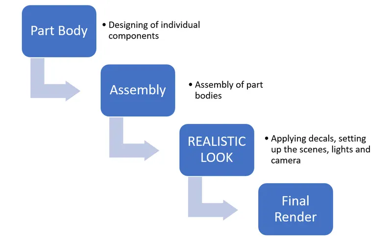
Design Methodology:
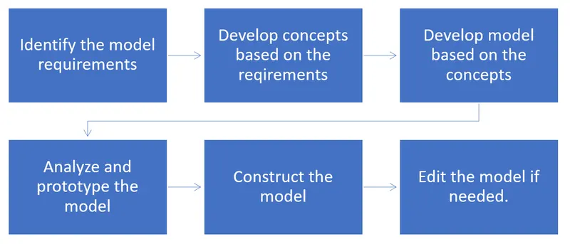
Tools and Features used in this project:
Sketch
These are 2D profile or cross section of the 3D models drawn in a sketcher module. Creating a model usually begins with a sketch.
3D sketches can also be made which is controlled by all the three axes.
Various Sketch tools used in this project:
SKETCH ELEMENTS
PLANES
Planes are the references widely used to place or refer a feature. you can sketch on planes with various sketch entities. Planes can be crated in part or assembly environment
DIMENSIONS
Dimensions in sketch environment allow you to specify dimensions between entities such as length, radius, etc. When you change dimensions, the size of the and the shape of the sketch entities will change.
The software uses two types of dimensions Driving dimensions and driven dimension
SKETCH DEFINITIONS (Default)
Fully defined – black color
Under defined – blue color
Over defined – yellow color
SKETCH ENTITIES
We can create a sketch with the help of these sketch entities. Some of the sketch entities are Line, Circle, Rectangle.
LINE
Line entity is used to draw lines in many ways on the plane
CENTRELINE
Centerline entity is used to sketch a centerline for reference purpose. Use centerline entity as a reference for creating symmetrical sketch and revolved features.
MIDPOINT LINE
Midpoint line entity is used to create a line that is symmetrical from its midpoint.
CIRCLE
Circle tools is used to create circle entities.
There are two types of circles:
- Two - point circle
- Perimeter circle
ARC
Arc tool is used to create an arc entity for different situation. There are three types of arcs:
- CenterPoint arc
- Tangent arc
- Three - Point arc
ELLIPSE
Ellipse tool is used to create an ellipse entity. We can specify any appropriate combination of the following parameters to define the ellipse center X Coordinate, Centre y Coordinate, Radius 1, Radius 2
RECTANGLE
A rectangle tool entity is used to create various types of rectangles for different situation
Types of rectangles are:
- Corner rectangle
- Centre Rectangle
- Three - Point Centre Rectangle
- Three - Point corner Rectangle
SLOT
A Slot tool is used to create various types of slot entities for different situation.
Types of slots:
- Straight slot
- Centre point Straight slot
- Three - Point Arc Slot
- Centre point Arc slot
POLYGON
A polygon Tool is used to create equilateral polygons with any number of sides between 3 and 40
Parameters of Polygon are
Number of Sides, Inscribed and Circumscribed circle, Circle diameter, Angle
SPLINE
A spline tool is used create the curved spline entity.
There are three types of splines available.
They are:
- Spline
- Style Spline
- Equation Driven Curve
You can define and modify them using several controls including spline points, spline handles and control polygons
SKETCHING POINT
Point tool is used to create the point entities in sketches and drawings.
SKETCH RELATION TYPES
- Coincident
- Collinear
- Concentric
- Equal
- Fix
- Horizontal
- Intersection
- Midpoint
- Normal
- Parallel
- Offset
- Perpendicular
- Symmetric
- Tangent
- Vertical
- Pierce
DIMENSIONS
Sketches are displayed in various states. In order to fully define the sketch, we add relation and apply dimensions using the smart dimension tool.
SKETCH EDITING TOOLS
Sketch Tools are commonly used to edit the sketch entities. Some of the sketch tools are Fillet, Chamfer, Trim, Mirror etc.
SKETCH FILLET
The sketch Fillet tool is used to trim the corner at the intersection of two sketch entities to create a tangent arc.
CHAMFER
A Chamfer tool is used to apply a chamfer to the sketch entities in 2D and 3D sketches
Parameters of chamfer are Angle -Distance, Distance – Distance
OFFSET
An offset tool is used to offset the sketch entities to the specified distance
CONVERT ENTITIES
The convert Entities tool is used to create one or more curves in a sketch by projecting a edge, loop, face, curve, or external sketch contour, set of edges or set of sketch curves onto the sketch plane/face
TRIM ENTITIES
The trim tool is used to delete the unwanted sketch entities select the trim type based on the entities you want to trim. Types of trim tool Power Trim, corner, Trim away inside, trim away outside, Trim to closet
EXTEND ENTITIES
The extend tool is used to add the length of the sketch entity up to another point of the entity
MIRROR ENTITIES
The mirror tool is used to mirror the pre-existing 2D sketch entities with respect to some reference
SKETCH PATTERNS
Sketch patterns are used to create linear or circular sketch patterns using elements from sketch entities
SKETCH BLOCKS
Sketch blocks in Solidworks provide a simple and useful method of grouping the entities together.
EXTRUDE
Extrude are used to create a feature (boss/base) by protruding a section in the normal direction. As with the base, all extrudes begin with a section sketch.
REVOLVE
The revolve tool is used to add a material by revolving one or more profiles around a centerline. you can create revolve boss/base, revolved cuts or revolved surfaces. The revolve feature can be solid, a thin feature, or a surface
SWEPT
A Swept/sweep is used to create a base, boss, cut or surface by moving a profile (section) along a path and controlling the shape with the guide curves (optional).
LOFTS
A Loft is used to create a feature by making transmissions between profiles. It can be a base, boss, cut or surface you can create a loft using two or more profiles
DOME TOOL
The dome tool is used to create dome like shapes in the model
EDIT FEATURES
Edit features are the secondary features; means they can be created only on the already existing features. These include cut, fillets, shells and other features
CUT FEATURES
The cut feature is used to remove material from a part or an assembly. With multibody parts, we can use cut features to create disjoint parts. Also, you can control which parts to keep and which parts to effect by the cut.
EXTRUDED CUT TOOL
The Extruded cut tool is used to remove all the materials, defined by a sketch profile protruded in the normal direction to a specified distance
SWEPT CUT TOOL
The swept cut tool is used to remove the materials by sweeping a profile along the defined path
SURFACE MODELLING
Surface modelling gives you the ability to build out a visual representation of an object exterior and its contours. In other words, it’s a surface.
FEATURES DESCRIPTION
LOFTED SURFACE
Loft surfaces are generated by multiple 3D curves or existing edges creating a smooth tangency between the selected curves.
SWEPT SURFACES
Sweep Surfaces are surfaces that are generated from a section curve position along path.
SURFACE KNIT
Surface knit is used to knit the two free edges/open edges of the surface together. Also, it reduces the gap between the two edges of the surface.
REVOLVE CUT
The Revolved cut tool is used to remove material by revolving one or more profiles around a centerline
LOFTED CUT
The Lofted cut tool is used to material by transitions between different profiles
ENGINEERING FEATURES
FILLET TOOL
The Fillet tool is used to create a rounded internal or external face on the part. you can fillet all edges of a face, selected sets of faces, selected edges or edge loops
CHAMFER TOOL
The Chamfer tool is used to create a beveled feature on selected edges, face or a vertex
SHELL TOOL
The Shell tool is used to hollow out a part, leaves open the faces you select and create thin-walled feature on the remaining faces.
If You do not select any face on the model, you can shell a solid part, creating a closed and hollow model. you can also shell a model using multiple thickness
PATTERNS
We can create a linear pattern, a circular pattern, a curve driven pattern, a fill pattern, or use sketch points or table coordinates to create the pattern. When a pattern or mirror features split single bodies into multiple bodies, we can select which bodies to keep and specify which configuration to keep up to date. The software also supports a full preview of pattern and mirror features
LINEAR PATTERN TOOL
Linear pattern tool is used to create multiple instances of one or more features that you can space uniformly along one or two linear paths
CIRCULAR PATTERN TOOL
Use circular pattern tool to create multiple instances of one or more features that you can space uniformly around an axis
SPLIT LINE TOOL
The Split line tool is used to project an entity (sketch, solid, surface, face, plane or surface spline) on to surfaces or curved/planar faces. It divides a selected face into multiple separate faces. You can split curves into multiple bodies with one command.
PROJECTED CURVE TOOL
The projected curve tool is used to project a sketched curve onto a model face to create a 3D curve. You can also create a 3D curve that represents the intersection of two extruded surface generated by creating sketches on two intersection planes
COMPOSITE CURVE TOOL
The Composite curve tool is used to join the sketch entities, edges and so on.
SURFACE MODELLING
Surface modelling gives you the ability to build out a visual representation of an objects exterior and its contours. In other words, it’s a surface.
FEATURES DESCRIPTION
LOFTED SURFACE
Loft surfaces are surfaces generated by multiple 3D curves or existing edges creating a smooth tangency between the selected curves.
SWEPT SURFACES
Sweep Surfaces are surfaces that are generated from a section curve position along path.
SURFACE TRIM
Primarily used to cut away material from a surface, and provides to modes: standard and mutual.
EXTEND SURFACE
Extend surface is used to extend the surface which is already created. There are different options available on the extended surface. We can extend the surface as same surface or we can extend the surface tangent to the surface.
SURFACE KNIT
Surface knit is used to knit the two free edges/open edges of the surface together. Also, it reduces the gap between the two edges of the surface.
PARTS IN AMERICAN CHOPPER
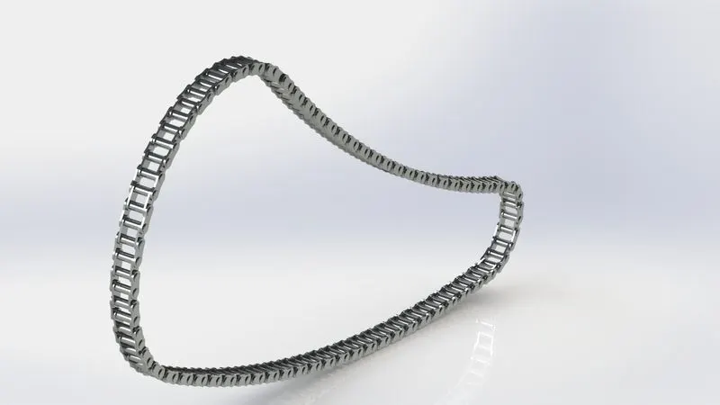
Chain
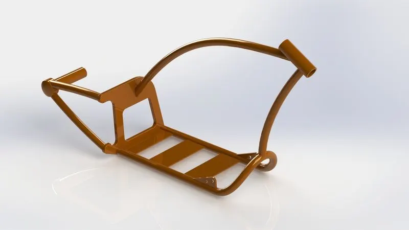
Chassis
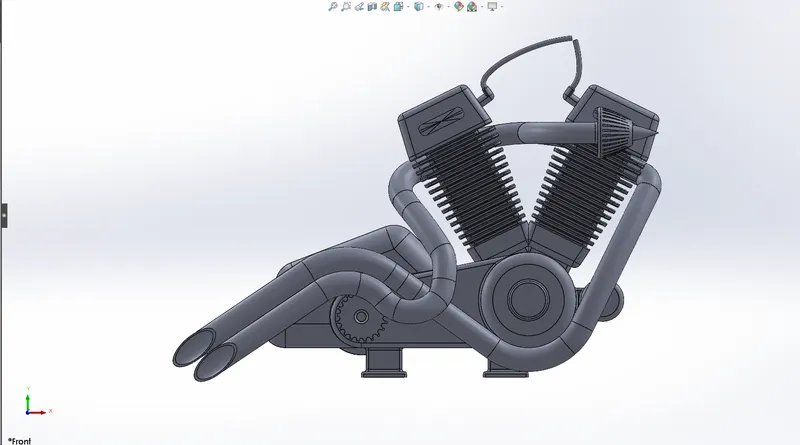
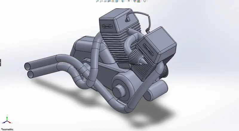
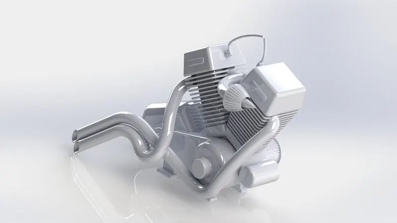
Engine
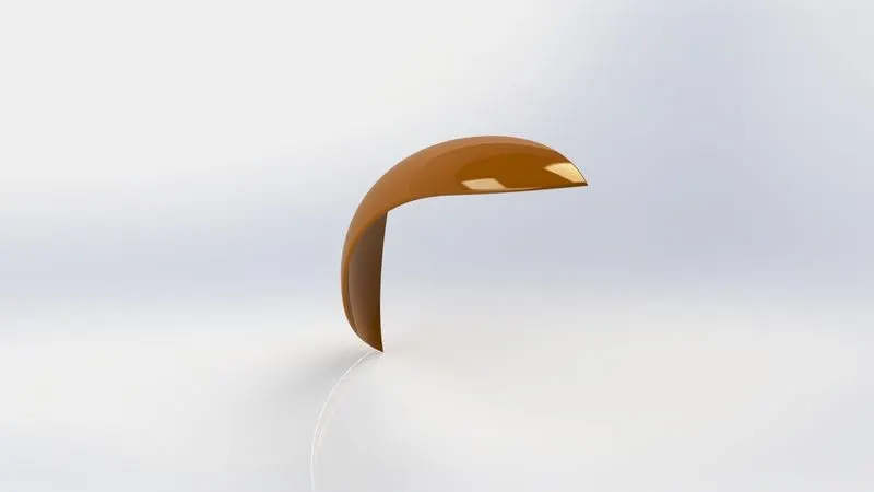
Front Fender
Rear Fender
Front Fork
Gas Tank
Kickstand
Oil Tank
Pedal
Transmission Belt
Front Wheel
Rear Wheel
Part Body
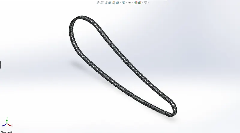
Chain:
The chain on the bike is responsible for transferring the mechanical power from the engine to the rear wheel of the bike.
Tools Used:
Sketch tools:
- Circle
- Line
- Construction line
Features:
- Extrude boss/base
- Fillet
- Circular pattern
- Mirror
Chassis:
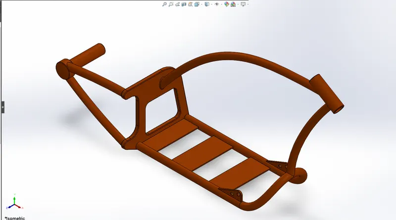
The chassis is the skeleton of the motor cycle which consists of all the parts mounted on it. It is constructed using the hollow pipes.
Tools Used:
Sketch Tools:
- Line
- Spline
- Circle
- Construction line
- Three Point Arc
Features:
- Projected curve
- Sweep
- Extrude base/boss
- Cut extrude
- Chamfer
- Fillet
- Creating reference plane
- Dome
- Revolve
- Split
- Combine
- Mirror
Engine:
An engine or motor is a machine designed to convert one form of energy into mechanical energy. Heat engines, like the internal combustion engine, burn a fuel to create heat which is then used to do work.
Tools Used:
Sketch Tools:
- Line
- Circle
- Construction line
- Circular sketch pattern
- Spline
- ThreePoint Arc
Features:
- Extrude base/boss
- Revolve
- Cut Extrude
- Fillet
- Creating reference plane
- Chamfer
- Linear pattern
- Dome
- Circular Pattern
- Sweep
- Projecting curves
- Composite curves
- Split
- Mirror
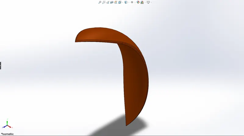
Front Fender: Fender is the American English drum for the part of an automobile, motor cycle its primary purpose is to prevents sand, mud, rocks, liquids and other road spray from being thrown into the air by rotating the tire.
Tools Used:
Sketch Tools:
- Circle
- Line
- Construction line
- Spline
Features:
- Revolve
- Split
- Fillet
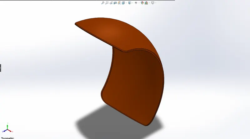
Rear Fender: Fender is the American English drum for the part of an automobile, motor cycle its primary purpose is to prevents sand, mud, rocks, liquids and other road spray from being thrown into the air by rotating the tire.
Tools Used:
Sketch Tools:
- Circle
- Line
- Construction line
Features:
- Revolve
- Split
- Fillet
Front Fork: A motor cycle fork is a part of a bike that holds a front wheel. The fork consists of bearings and hydraulic oil which also acts as a suspension. The handle bar of the bike is mounted on fork.
Tools Used:
Sketch Tools:
- Line
- Circle
- Spline
Features:
- Extrude base/boss
- Cut extrude
- Revolve
- Fillet
- Dome
- Linear pattern
- Cut revolve
- Body move/copy
- Projected curve
- Sweep
- Creating reference plane
- Combine
- Mirror
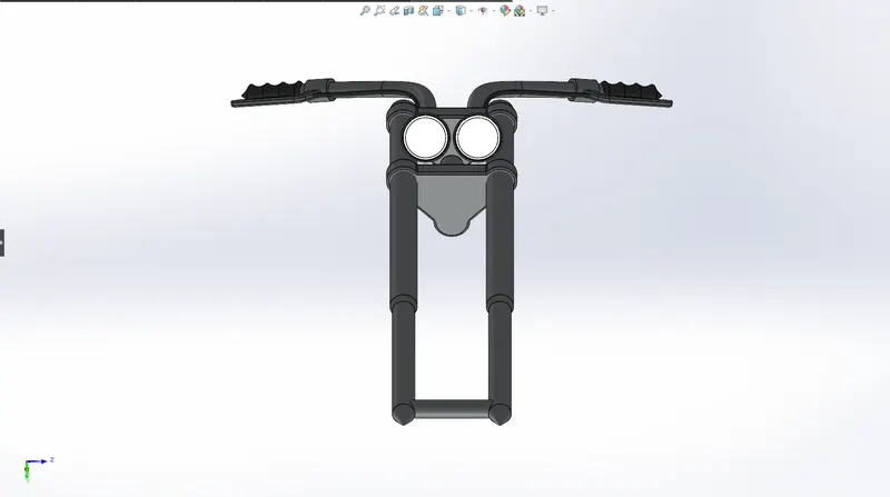
Gas tank: A gas tank is a safe container for flammable fluids. Though any storage tank for fuel may be so called, the term is typically applied to part of an engine system in which the fuel is stored and propelled fuel pump or released (pressurized gas) into an engine. Fuel tanks range in size and complexity from the small plastic tank of a butane lighter to the multi-chambered cryogenic space shuttle external tank.
Tools Used:
Sketch tools:
- Spline
- Line
- Circle
- Three-Point Arc
Features:
- Creating Reference plane
- Surface sweep
- Surface trim
- Projected curve
- Surface loft
- Boundary surface
- Mirror
- Surface knit
- Split line
- Surface extrudes
- Fillet
- Cut sweep
- Shell
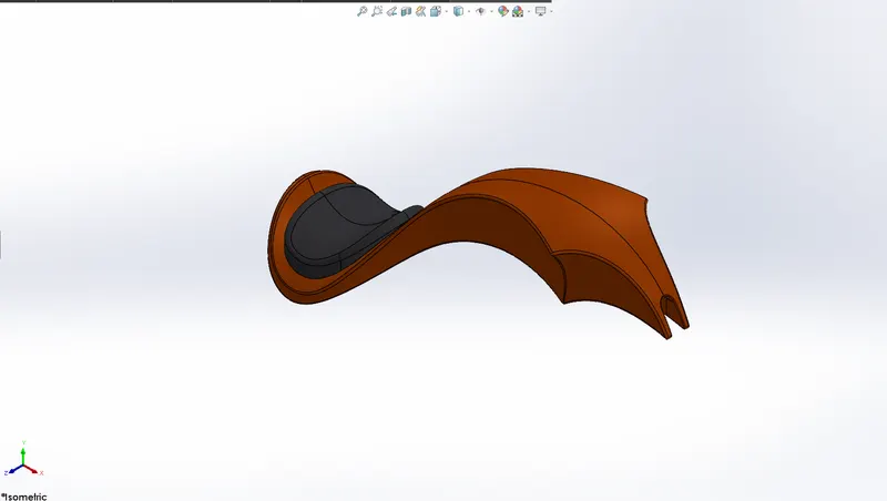
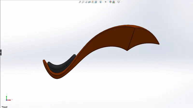
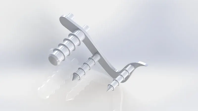
Kick stand: A kick stand is a device on a motor cycle that allows the bike to be kept upright without leaning against another object or the aid of the person. A kick stand is usually a piece of metal that flips down from the frame and makes contact with the ground.
Tools used:
Sketch tools:
- Ellipse
- Spline
- Rectangle
- Midpoint line
- Circle
Features:
- Extrude boss/base
- Cut extrude
- Loft
- Dome
- Split
- Fillet
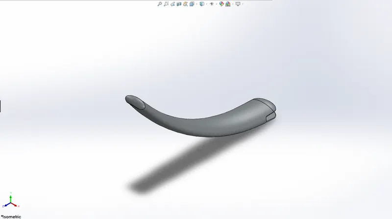
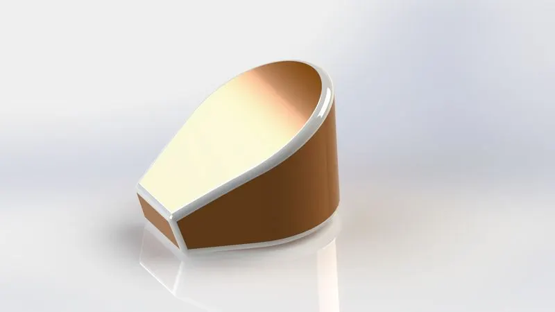
Oil tank: An oil tank has the purpose of storing lube oil to lubricate the engine parts to avoid wear and tear.
Tools used:
Sketch tools:
- Line
- Three-point Arc
Features:
- Extrude base/boss
- Combine
- Fillet
- Shell
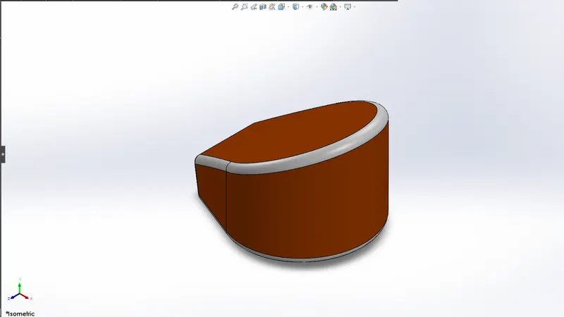
Pedal: A pedal has the function of shifting the gears to get the desired speed from the engine and also applying the breaking force.
Tools used:
Sketch tools:
- Line
- Three – point arc
- Circle
- Spline
Features:
- Extrude base/boss
- Revolve
- Fillet
- Chamfer
- Dome
- Linear pattern
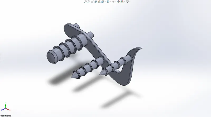
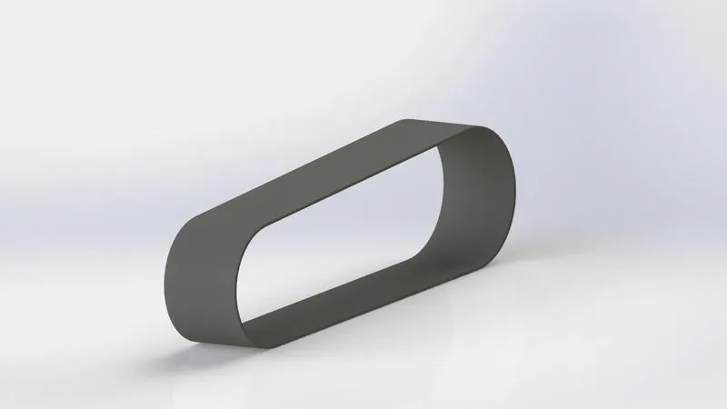
Transmission belt: It is a loop of flexible material used to link two or more rotating shaft mechanically, most often parallel. Belts may be used as a source of motion, to transmit power efficiently or to track relative movement.
Tools used:
Sketch tools:
- Line
- Three – point arc
Features:
- Extrude base/boss
- Fillet
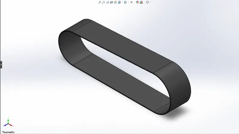
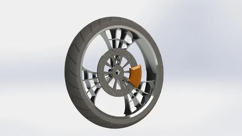
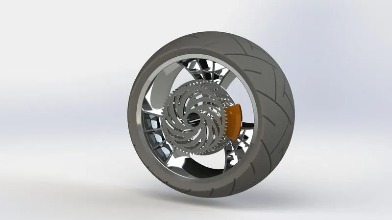
Front wheel: A wheel is a circular block of a hard and durable material where the center has been bored with the circular hole through an axle bearing about which the wheel rotates.
Tools used:
Sketch tools:
- Line
- Rectangle
- Sketch fillet
- Three – point arc
- Construction line
- Spline
- Circle
- Linear sketch pattern
Features:
- Extrude boss/base
- Extrude cut
- Revolve
- Revolve cut
- Circular pattern
- Combine
- Fillet
- Chamfer
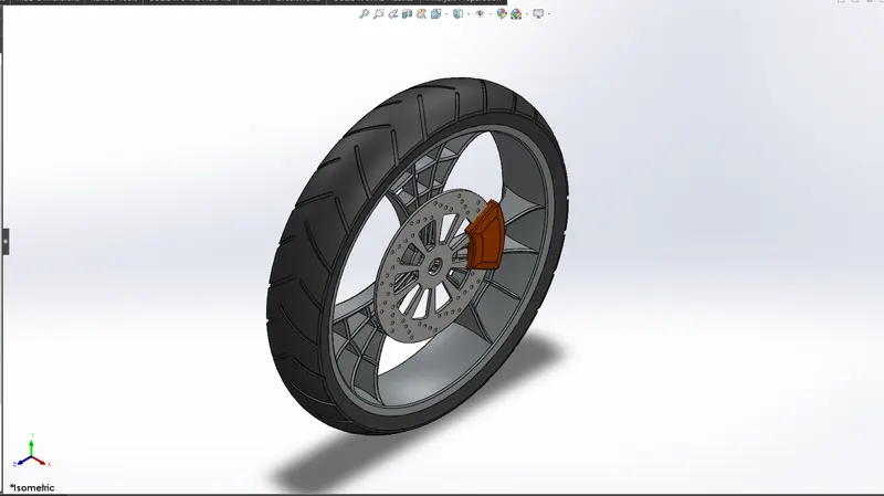
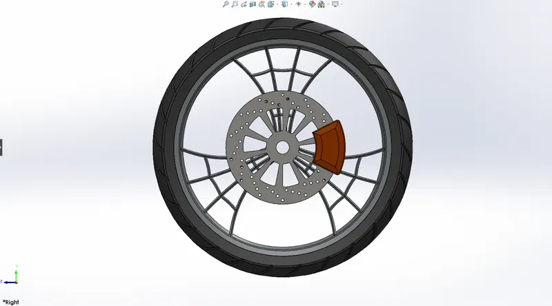
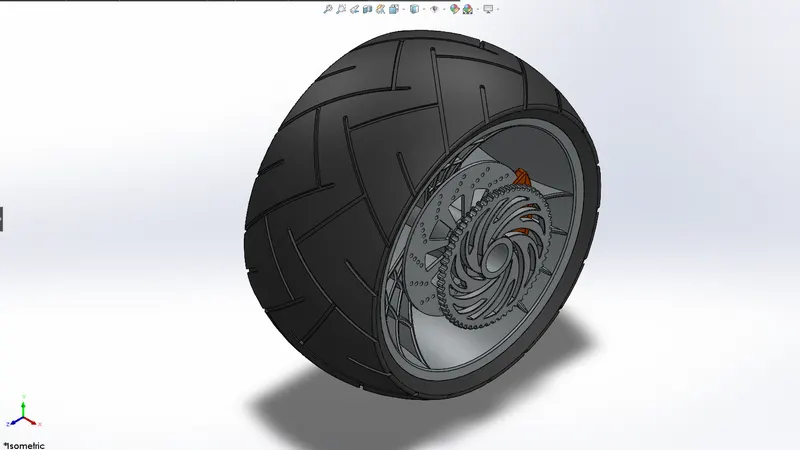
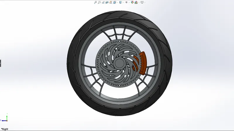
Rear wheel: A wheel is a circular block of a hard and durable material where the center has been bored with the circular hole through an axle bearing about which the wheel rotates.
Tools used:
Sketch tools:
- Line
- Rectangle
- Sketch fillet
- Three – point arc
- Construction line
- Spline
- Circle
- Linear sketch pattern
Features:
- Extrude boss/base
- Extrude cut
- Revolve
- Revolve cut
- Circular pattern
- Combine
- Fillet
- Chamfer
ASSEMBLY
An assembly is a collection of related parts saved in one SOLIDWORKS document file with Assemblies:
- It contain parts or other assemblies called subassemblies.
- Display movement between related parts within their degrees of freedom. The components in an assembly are defined in relation to each other using assembly mates.
- The mated components create the spigot subassembly. Later, you include this subassembly in the main vanity assembly, mating it to the other components in the vanity assembly.
MATES
Mates position the components in an assembly precisely with respect to each other. Positioning the components defines how they move and rotate with respect to each other. Mates create geometric relations, such as coincident, perpendicular, and tangent. Each mate is valid for specific combinations of geometry such as cones, cylinders, planes, and extrusions.
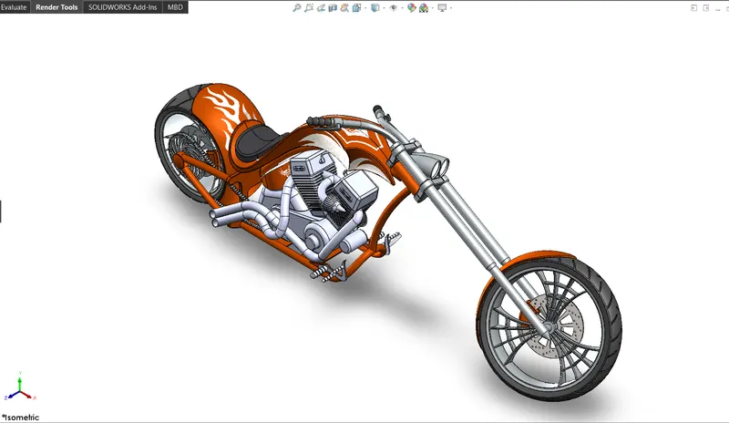
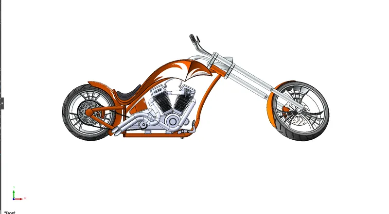
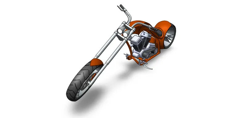
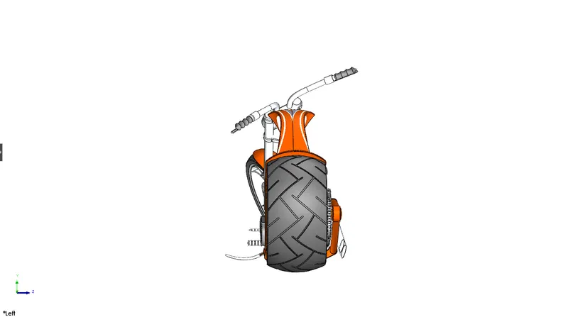
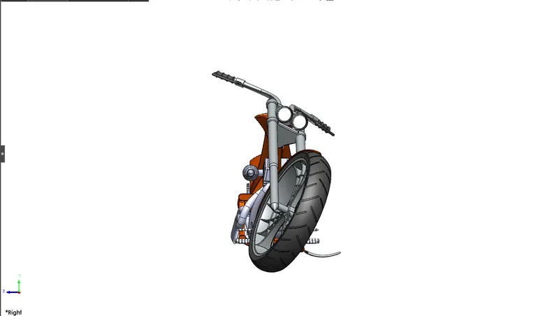
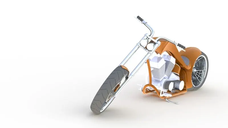
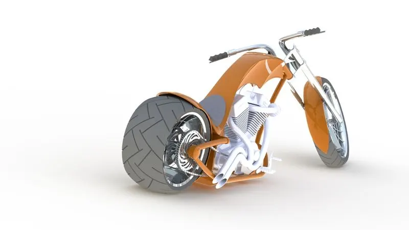
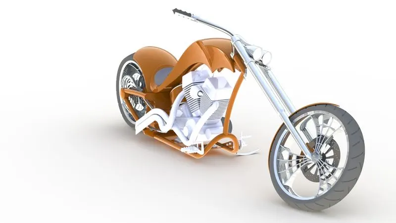
AMERICAN CHOPPER ASSEMBLY:
SOLIDWORKS PHOTOVIEW 360
Photo View 360 is a SOLIDWORKS add-in that produces photo-realistic renderings of SOLIDWORKS models. The rendered image incorporates the appearances, lighting, scene, and decals included with the model. Photo View 360 is available with SOLIDWORKS Professional or SOLIDWORKS Premium.
Render Images:
Parts:
Chain
Chassis
Engine
Front fender
Rear fender
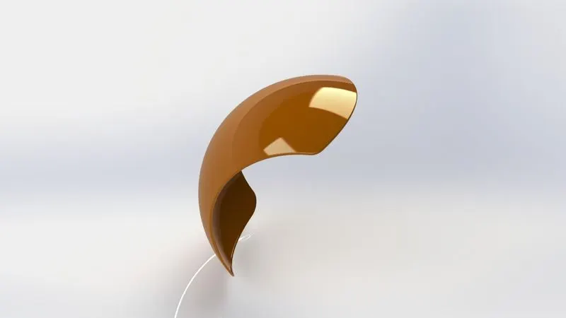
Front fork
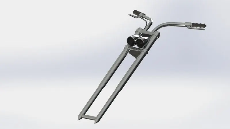
Gas tank
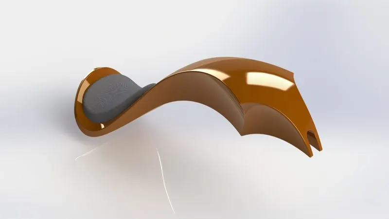
Kickstand
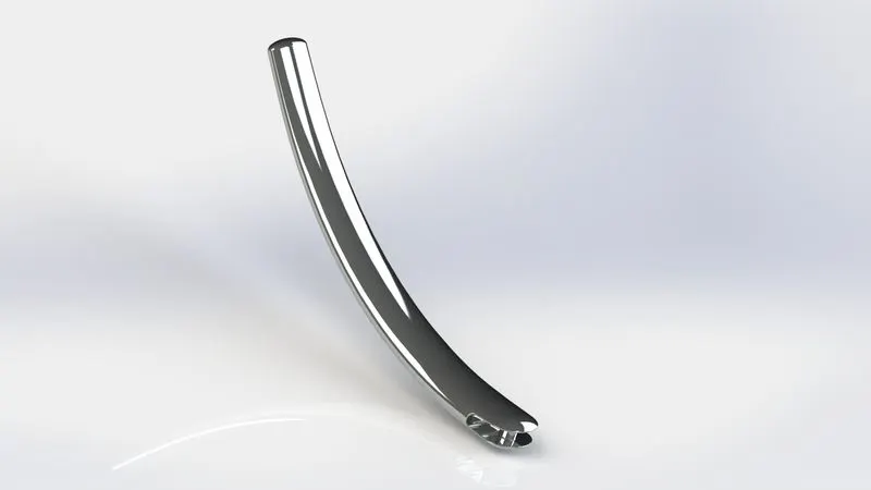
Oil tank
Pedal
Transmission belt
Front wheel
Rear wheel
ASSEMBLY:
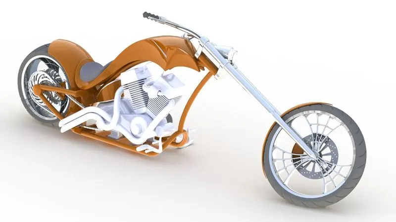
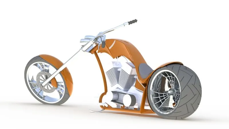
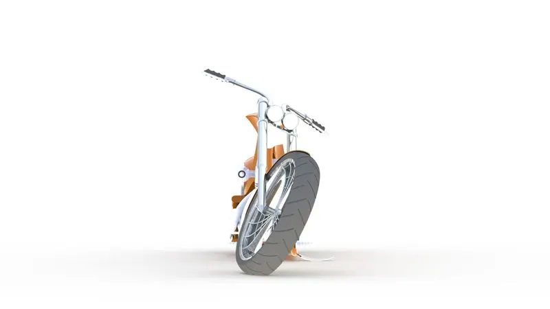
Conclusion:
The Part modeling, Assembly, Photo realistic rendering of the American chopper bike has completed using SOLIDWORKS 2021.