Photo Realistic Rendering
Photo Realistic Rendering
Objective:
- Write the steps involved in the Assembly of Chopper Model.
- Perform rendering on the complete assembled Chopper Model.
Introduction:
We create a 3D model using a 3D design approach, we design a part, from the initial sketch to the final result. From this model, we can create 2D drawings or mate components consisting of parts or subassemblies to create 3D assemblies. We create a 3D model that can also create 2D drawings of 3D assemblies. When designing a model using SOLIDWORKS, we can visualize it in three dimensions, the way the model exists once it is manufactured.
The basic SOLIDWORKS document types are parts, assemblies, and drawings. For example, we create a part before we create an assembly. Sketches The sketch is the basis for most 3D models. Creating a model usually begins with a sketch. From the sketch, you can create features. You can combine one or more features to make a part. Then, you can combine and mate the appropriate parts to create an assembly. From the parts or assemblies, you can then create drawings. A sketch is a 2D profile or cross-section. To create a 2D sketch, you use a plane or a planar face. In the SOLIDWORKS application is that any change you make to a part is reflected in all associated drawings or assemblies.
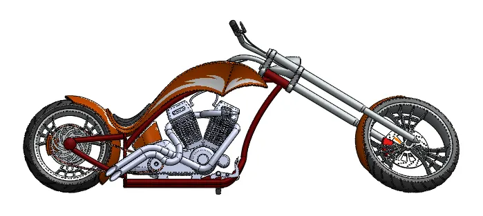
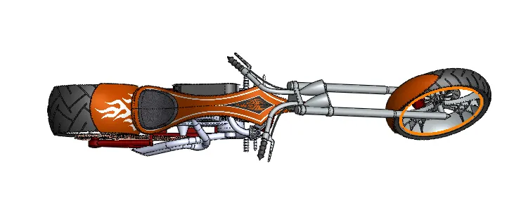
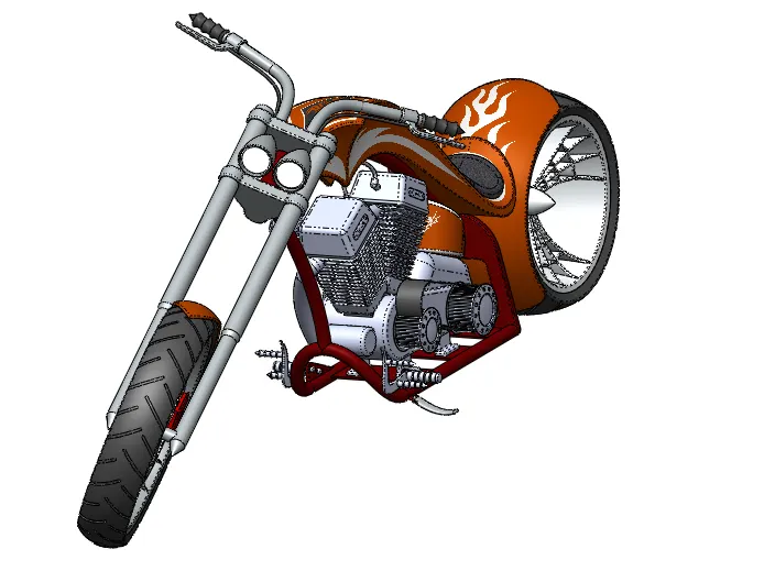
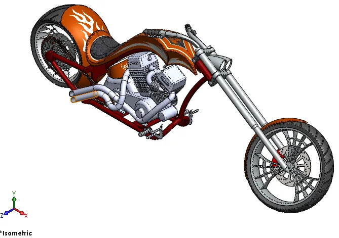
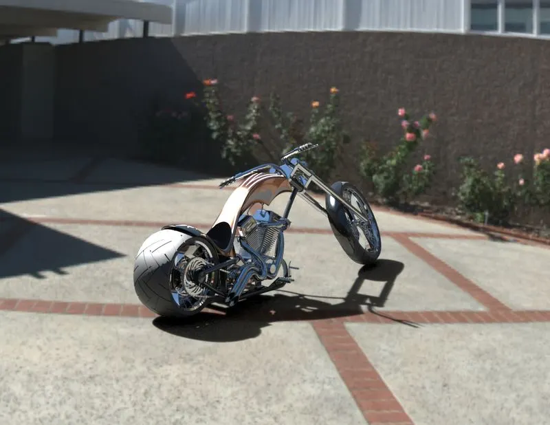
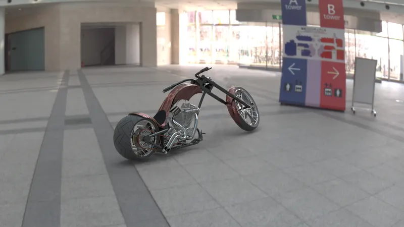
Here we are going to design an American chopper model and will do rendering on it to give it a realistic look.
Rendering:
A process of generating a photorealistic and non-photorealistic image with a computer program. We have multiple ways to perform this but here we are doing it using SolidWorks Visualize.
Design Method:
Before we actually design the model, it is helpful to plan out a method of how to create the model. After we identify needs and isolate the appropriate concepts, we can develop the model: Create the sketches and decide how to dimension and where to apply relations. Sketches Select the appropriate features, such as extrudes and fillets, determine the best features to apply, and decide in what order to apply those features. Features Assemblies Select the components to mate and the types of mates to apply.
Design methodology:
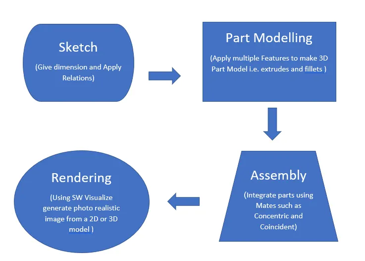
Features:-
- Once we complete the sketch, we can create a 3D model using features such as an extrude, revolve.
Extrude:
To create a 3D base feature, the sketch is extruded normal to the sketch plane. This adds material to a part by building upon the base.
Revolve:
The Revolve tool revolves a sketch profile around a centreline at a specified angle. A centreline creates an axis that is construction geometry; it is not built into the feature.
Cut-Extrude:
The Cut-Extrude tool is similar to an extrude feature, except that it removes material from the model instead of adding material.
- Other sketch-based features such as lofts, dome, and sweeps use a profile along a path.
Dome:
We can create a bump-type face on the top of any surface using this feature. We can even reverse this feature to see the opposite effect on the surface.
Loft:
It creates a feature by making transitions between two or more sketch profiles. When we create a loft, the sketch profiles must reside on different planes or planar faces.
Shell:
As the loft creates a solid feature, whereas the Shell tool hollows out and removes material. When we shell a part in SOLIDWORKS, selected faces are removed and thin faces remain on the rest of the part.
Sweep:
This tool projects a profile along a path. For example, a profile is a circular sketch, and the path is a sketched arc and a tangent vertical line. The circular profile remains the same shap and diameter for the entire sweep.
- Another type of feature is called an applied feature, which does not require a sketch. Applied features include fillets, chamfers, or shells. They are called “applied” because they are applied to existing geometry using dimensions and other characteristics to create the feature.
Fillet:
We can round off sharp edges by adding fillet features to the model. When we create a fillet, we set the radius to determine the smoothness of the edges.
Chamfer:
The Chamfer tool creates beveled faces. A chamfer, like a fillet, is an applied feature and does not require you to make a sketch to create the feature.
Convert Entities:
The Convert Entities tool lets us create a sketch by projecting a set of edges onto the sketch plane.
Pattern:
There is multiple pattern option like circular, line, etc. These patterns create multiple instances of a selected feature along a selected path.
Split:
Use the Split feature to create multiple parts from an existing part. We can create separate part files, and form an assembly from the new parts. We can split one or more solid or surface bodies. To split a surface, the Trimming Surface must extend past the boundaries of the surface to split.
The Consume cut bodies under Resulting Bodies, the solid body displayed in the graphics area is the original solid body minus the new parts.
Combine:
In a multibody part, we can combine multiple bodies to create a single body. We can only combine bodies contained within one multibody part file. We cannot combine two separate parts. However, we can create a multibody part by using Insert Part to place one part into the other part file. Then we can use Combine on the multi-body part. There are three different ways to use Combine; we can add, subtract, and find the common area of two different bodies.
Surface Knit:
It is a tool that can combine two or more surfaces into one. We can select the “create solid” checkbox from the top of the knit surface Property Manager. For this option to be enabled, we must select the surfaces first and make sure that these surfaces are enclosed or form a closed volume.
Surface Trim:
You can use a surface, plane, or sketch as a trim tool to trim intersecting surfaces. You can also use a surface in conjunction with additional surfaces, as mutual trim tools.
Fill Surface:
We can use this feature to construct a surface to fill a gap in a model.
Appearances:
An appearance defines the visual properties of a model, including color and texture. Appearances do not affect physical properties, which are defined by materials.
Assemblies:-
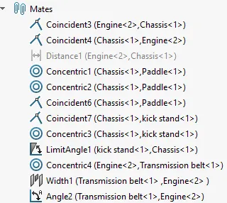
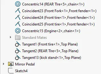
We can combine multiple parts that fit together to create assemblies. We integrate the parts in an assembly using Mates, such as Concentric and Coincident. Mates define the allowable direction of movement of the components.
Mates:
Mates position the components in an assembly precisely with respect to each other. Positioning the components defines how they move and rotate with respect to each other. Mates create geometric relations, such as coincident, perpendicular, and tangent. Each mate is valid for specific combinations of geometry such as cones, cylinders, planes, and extrusions. For example, if you mate a cone to another cone, the valid types of mates you can use include coincident, concentric, and distance
Depending on the complexity of the assembly (the number of separate components), we can open one or all of your components. After we open the components, we need to open a new assembly document into which we bring the components.
Coincident Mate:
To create a coincident mate between 2 components, we have to select the common faces to mate. When we apply the coincident mate, the component moves closer to each other. We can still slide them anywhere along the common face by dragging it with the left mouse button.
Concentric Mate:
For that, we have to select the edge of 2 components to make them concentric. Once we apply the concentric mate we can no longer move them. We can, however, use the left mouse button to drag them on its axis.
Part files Applied Feature Info:
|
Revolve Boss |
Fender, Wheel, Fork, chassis, Engine |
|
Boss Extrude |
Trans. Belt, stand, Chain, Wheel, paddle, Tank, Fork, Engine |
|
Extrude Cut |
Stand, Wheel, Engine |
|
Appearance |
Trans. Belt, stand, Fender, Chain, Wheel, paddle, Fork, chassis, Engine, Gas Tank |
|
Trim Entity |
Fender, Chain, Wheel, Fork, chassis, Engine |
|
Sketch |
Trans. Belt, stand, Fender, Chain, Wheel, paddle, Tank, Fork, chassis, Engine, Gas Tank |
|
Fillet |
Trans. Belt, stand, Fender, Chain, Wheel, paddle, Tank, chassis, Engine, Gas Tank |
|
Split |
Stand, Fender, Fork, chassis |
|
Loft |
Stand, Gas Tank |
|
Dome |
Stand, paddle, Fork, Engine |
|
Offset |
Trans. Belt, Fender, chassis, Engine |
|
Shell |
Tank |
|
Combine |
Tank, Fork, chassis, chassis |
|
Pattern |
Chain, Wheel, paddle |
|
Blocks |
Chain |
|
Chamfer |
Wheel, paddle |
|
Sweep |
Fork, chassis, Engine, Gas Tank |
Feature Manager Tree:
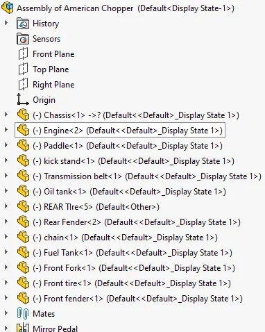
Applied Mates

Paddle
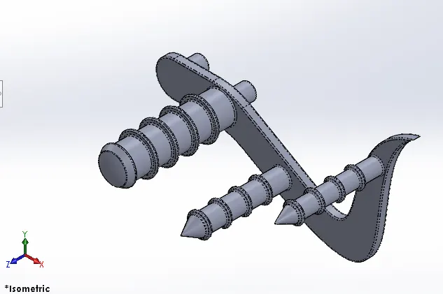
Bike Stand
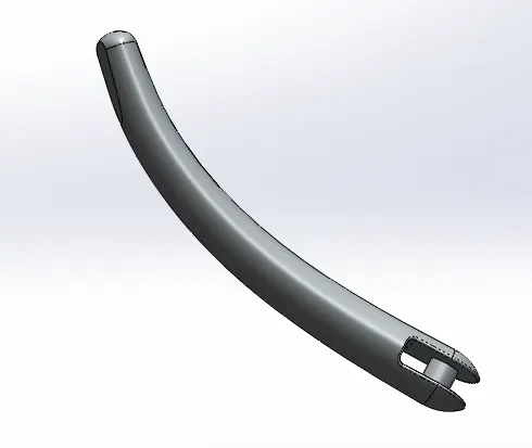
Tank
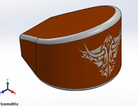
Chain
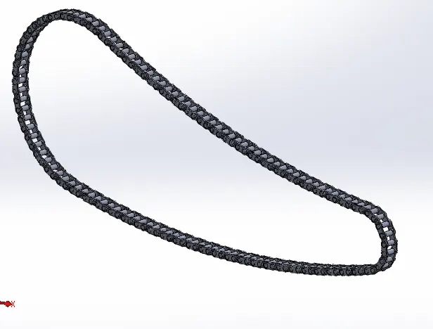
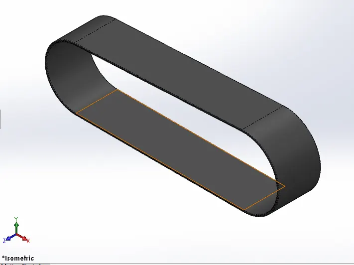
Transmission Belt
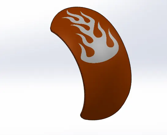
Rear Fender
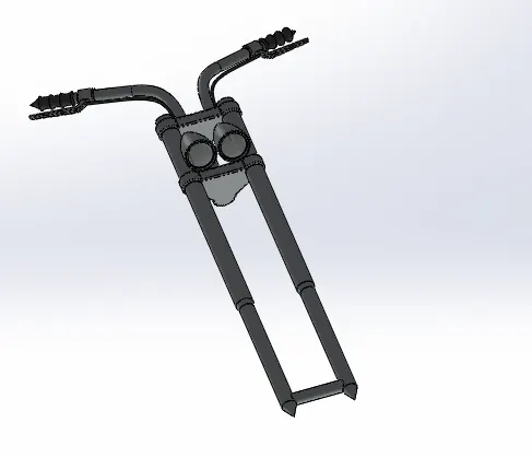
Front Fork
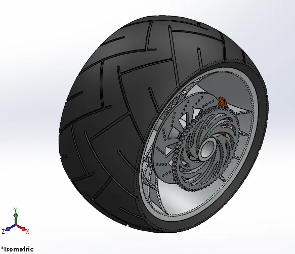
Rear Tire
Front Tire
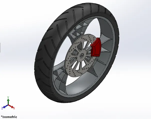
Chassis
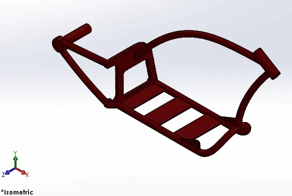
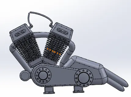
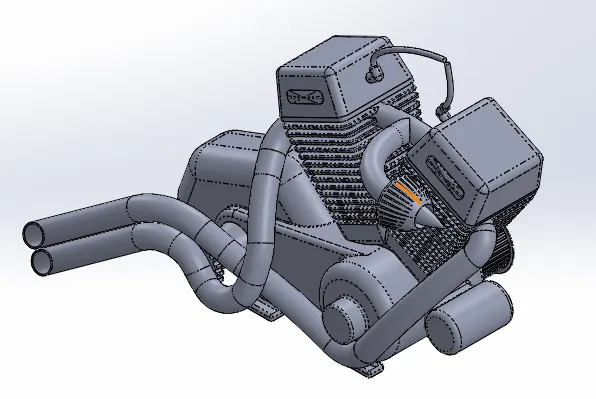
Engine
Complete Model
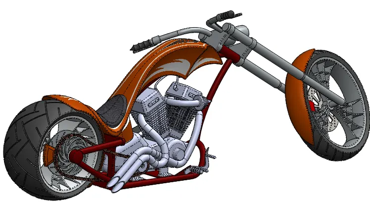
Rendered Image:
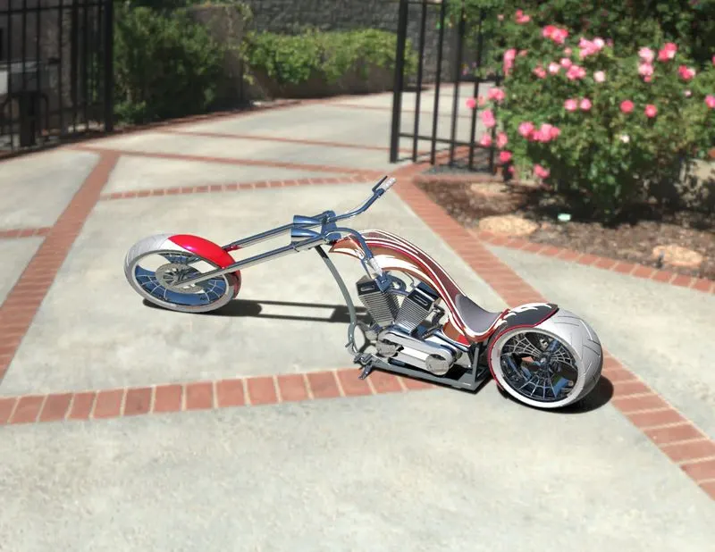
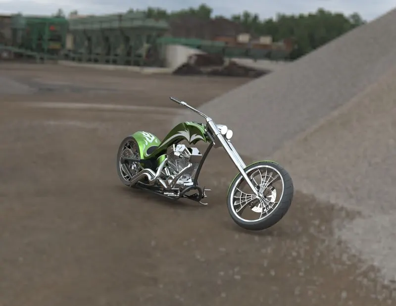
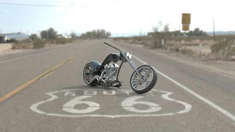
Conclusion:
We have successfully completed the rendering of the American Chopper Model from initial sketch, part modeling, assembly, and rendering using solid works visualize.
References:
https://help.solidworks.com/2019/english/SolidWorks/sldworks/HIDD_DVE_KNIT_SURFACE.htm
https://help.solidworks.com/2018/english/SolidWorks/sldworks/c_Split_and_Save_Bodies.htm
https://medium.com/@nccs/creating-a-solid-body-with-surfaces-in-solidworks-f63b3a391c2e
https://my.solidworks.com/solidworks/guide/SOLIDWORKS_Introduction_EN.pdf