Photo Realistic Rendering
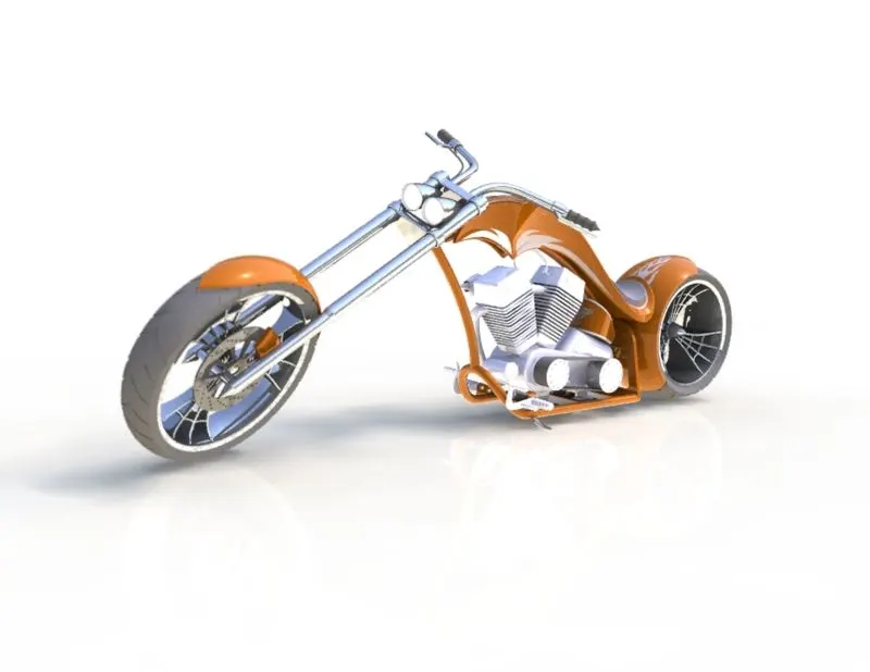
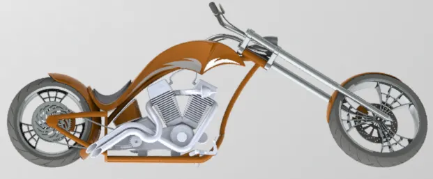
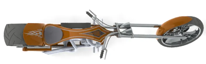
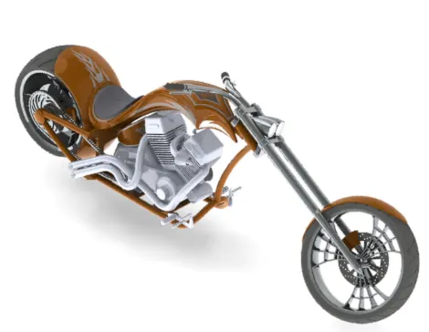
The American Chopper
Objective -
To design and assemble an American Chopper using the Solidworks 3D Design tool.
Introduction -
Solidworks is a user-friendly CAD (Computer Aided Design) software, where the user can develop various 3D models easily and in an effective manner.
Design Methodology/Approach -
The design approach to the American Chopper assembly was as follows :
- To collect the drawings or the data required to model the part.
↓
2. To create the required model using the constrained sketches.
↓
3. Modelling the part using the available features
↓
4. To apply the appropriate material to the designed part.
↓
5.To design the parts collectively and to use them to create an assembly.
↓
6. Applying proper mates to constrain the movement of parts in an assembly.
Description -
The various parts/components designed for the American Chopper assembly are :
1. Transmission Belt
2. Kick Stand
3. Front fender
4. Oil tank
5. Chain
6. Pedal
7. Front wheel
8. Rear wheel
9. Front Fork
10. Rear fender
11. Chassis
12. Engine
13. Gas tank
The process of designing the individual components and later assembly of the entire components is explained below :
Week 1 :
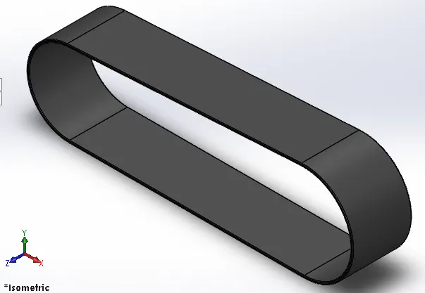
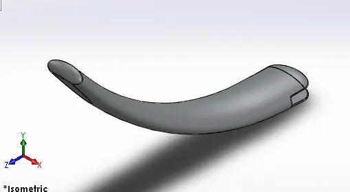
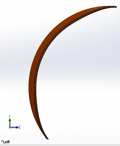
1. Deisgn of the Transmission Belt, Kickstand, Front fender
These parts were designed by using the Extrude, revolve, dome and fillet features to the 2D sketch. Extrude feature helps in obtaining a 3D model from the 2D sketch by translating in the required planes. Revolve feature adds the material around a centre line of a sketch.
Week 2 :
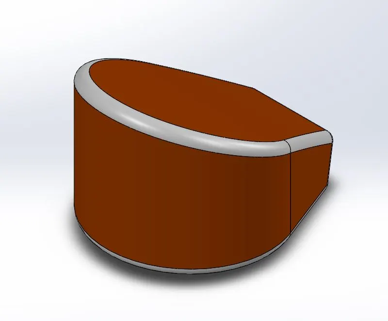
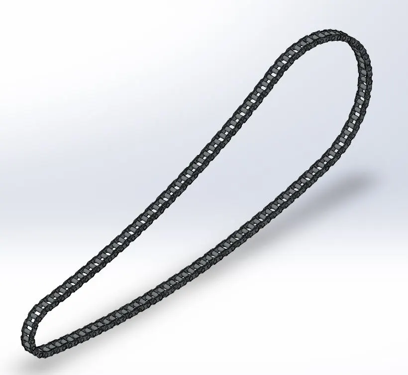
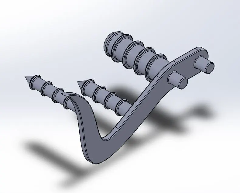
Design of the Oil tank, Chain and Pedal
These parts were designed by using the Sweep, revolve, extrude cut, splines and trim features to the 2D sketch.The sweep command adds the material along a cosed path in the specified direction. The splines are the most advanced and highly useful command where complex curves can be created with the help oftwo planes and a complex geometry can be built around the same.
Week 3 :
Design of the Front wheel
The front wheel was designed by using various commands such as circular pattern, revolve cut, sweep, extrude cut and combine.
Week 4 :
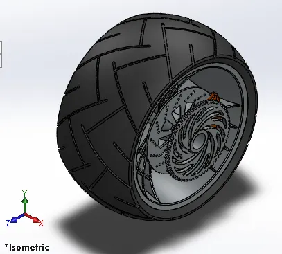
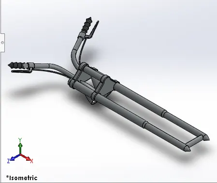
Design of the Rear wheel and Front Fork
The rear wheel was almost similar to the front wheel and few of the other commands used in this modelling were mirror pattern and projected curve.
Week 5 :
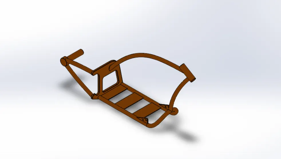
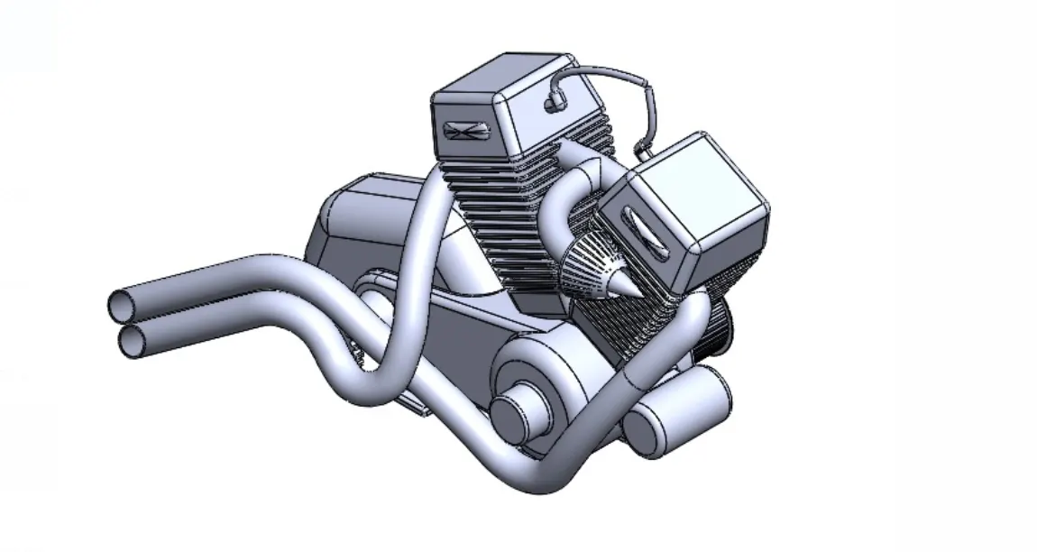
Design of the Chassis and Engine
The main commands used here are the sweep, revolve, extrude, dome, projected curve, split and mirror.
Week 6 :
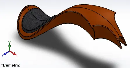
Design of the Gas Tank
The gas tank was a special model in the american chopper assembly where as the new features such as the surface loft, surface sweep, boundary surface and knit surface were introduced along with the revolve, extrude and the projected curve commands.
Assembly of American Chooper
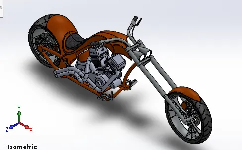
This was the end of the part modelling. Now as we had all the parts designed, the assembly of the american chopper was explained where we use the mates to assemble one part over the other part and completely constrain it. The type of mates used in the assembly were the concentric mate, parallel, angle, distance and advance mates.
Photoview 360
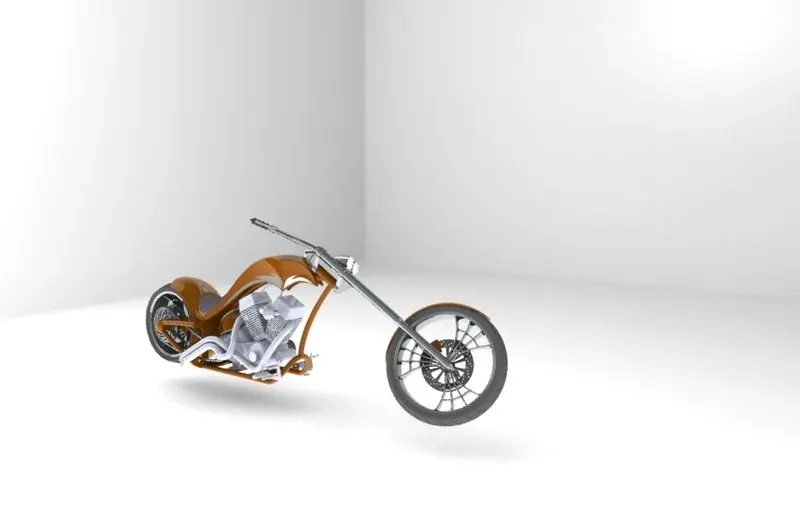
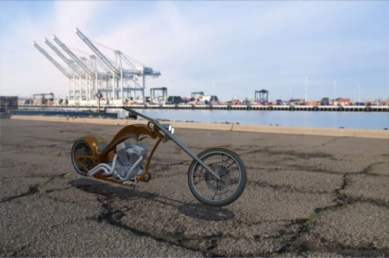
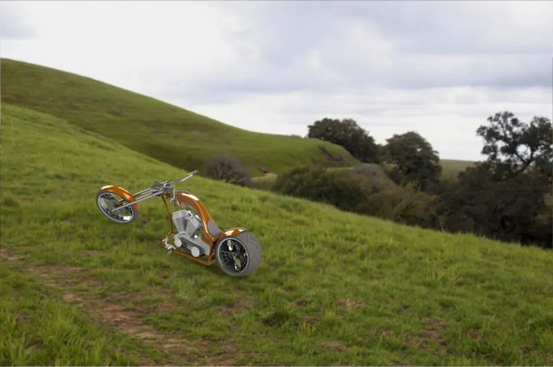
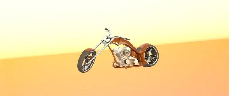
It helps in enhancing the design of the Americal Chopper by improving the image quality of the model. Various tools under the photoview 360 were used such as the decals, scenes, camera, lights etc.
Conclusion
This project really helped me in understanding the basics right understanding how to fully constrain the sketches to the fully constraining of the assemblies.