Photo Realistic Rendering
SKILL LYNC
PROJECT REPORT
MODELLING AND RENDERING OF AMERICAN CHOOPPER USING SOLIDWORKS
BY,
MOHAMMAD YASEEN SHAIK
Objective:
This project explains about the sketching, detailed designing of different parts of chopper and assembling them to get a complete model of the chopper using SolidWorks. It also tells about the rendering of the model using SolidWorks, PhotoView 360 to make the chopper more natural and realistic.
The main objective of this project are:
- To create individual parts of chopper using SolidWorks
- To assemble all the individual parts to get a realistic model
- To apply the Usage of decals, lights, camera
- To create realistic model and render it using PhotoView 360
Background:
SolidWorks is a solid modeling computer-aided design and computer-aided engineering computer program published by Dassault Systèmes. SOLIDWORKS uses a 3D design approach. As you design a part, from the initial sketch to the final result, you create a 3D model. From this model, you can create 2D drawings or mate components consisting of parts or subassemblies to create 3D assemblies. You can also create 2D drawings of 3D assemblies.
When designing a model using SOLIDWORKS, you can visualize it in three dimensions, the way the model exists once it is manufactured. It has lot of options like appearances, lights, decals, camera etc. which helps the model to get a realistic view.
Design Methodology:
The software used for creating American Chopper was SolidWorks and a add-in feature like PhotoView360 helps in rendering of the final model to get a realistic look.
The components of the model required to design a Chopper are:
- Chassis
- Engine
- Front wheel
- Rear Wheel
- Front fork
- Front Fender
- Rear Fender
- Oil Tank
- Chain
- Transmission belt
- Kick stand
- Foot pedals
- Gas tank
Basic definitions of design features are used in this project:
EXTRUDE:
The Extruded Boss is the most basic of all SolidWorks features, and extrudes a sketch along a straight line path to add material. As a sketched feature, it requires a sketch before use.
FILLET:
Fillets are classified as applied features, and as such do not require a sketch to be used. Fillets serve to round off edges and/or corners by adding or removing material, depending on whether the edge is internal or external. It should be noted that fillets of different sizes must be created as separate features.
SHELL:
The Shell command allows you to define a wall thickness and automatically hollow the part, while allowing faces to be removed as needed. If no faces are specified to be removed during a Shell feature, the part will be hollow, but this can only be seen by creating a cross section of the part.
REVOLVE:
This feature adds material by revolving a sketch around an axis. The feature can be either a solid, a thin feature, or a surface.
EXTRUDE CUT:
This feature will be a circular cut.
LOFT:
Loft creates a feature by making transitions between profiles. A loft can be a base, boss, cut, or surface.
SWEEP:
Sweep creates a base, boss, cut, or surface by moving a profile (section) along a path.
DOME:
A dome is a curved formation or structure. It is shaped like half of a sphere.
SPLIT:
To create multiple parts from an existing part.
DYNAMIC MIRROR:
Dynamic mirror, is similar to mirror entities however the line or lines to mirror about are selected beforehand then anything drawn in the sketch will be mirrored dynamically.
POWER TRIM:
To trim multiple, adjacent sketch entities by dragging the pointer across each sketch entity.
PATTERN:
A pattern consists of multiple instances of a feature. Select a pattern type and define dimensions, placement points, or a fill area and shape to place the pattern members.
COMBINE:
It allows you to add two bodies together, and keep the area that is common to them.
PROJECTED CURVE:
A sketched curve onto a model face to create a 3D curve.
COMPOSITE CURVE:
By combining curves, sketch geometry, and model edges into a single curve.
CONVERT ENTITIES:
It allows users to make a copied projection of a given sketch, face, or set of edges onto the active sketch plane
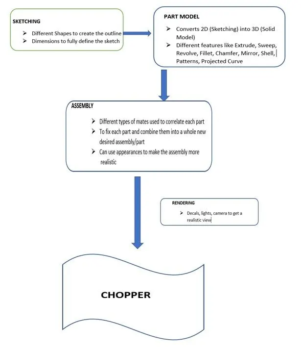
The below flow chart shows the steps to design a Chopper:
SKETCHING AND PART MODELS
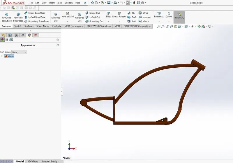
- CHASIS:
Chassis is the basic structure of a chopper where its ability and strength to maintain balance. All the components will assemble by taking Chassis as a reference.
Design: Used a ‘JPEG’ picture of American Chopper as a reference to create this part
Some of the key features involved to create a chassis:
- Sketch
- Offset
- Convert entities
- Project Curve
- Trim
- Sweep
- Split
- Revolve
- Cut extrude
- Fillet
- Combine
- ENGINE:
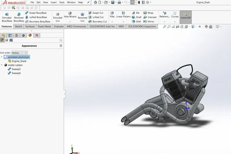
Engine is the heart of the Chopper. It converts chemical energy into the heat energy and then eventually the heat energy converted to Mechanical work (Rotational motion).
Design: Used a ‘JPEG’ picture of American Chopper as a reference to create this part.
Some of the key features involved to create an Engine:
- Sketch
- Trim
- Revolve
- Extrude Boss
- Extrude Cut
- Offset
- Convert entities
- Dome
- Projected Curve
- Composite Curve (Joining Two Curves)
- Fillet
- Mirror
- Sweep
- Circular Pattern
- Split
- FRONT WHEEL:
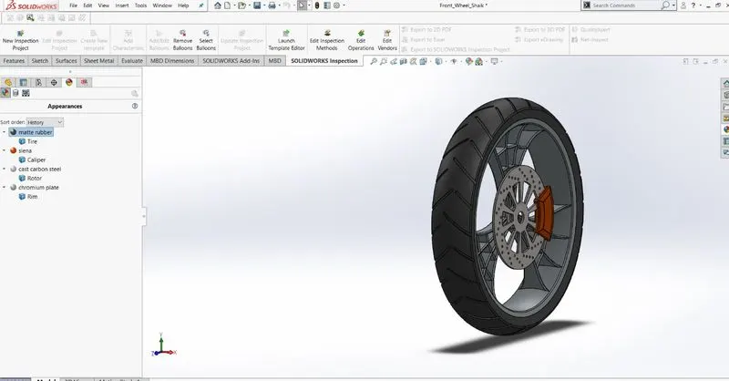
A circular object called wheel is used to carry forward the rotational motion and move the connected forward. A wheel has certain parts like Rim, Tire, Caliper.
Some of the key features involved to create a Front Wheel:
- Sketch
- Trim
- Revolve
- Extrude Boss
- Cut extrude
- Fillet
- Revolve cut
- Pattern
- Chamfer
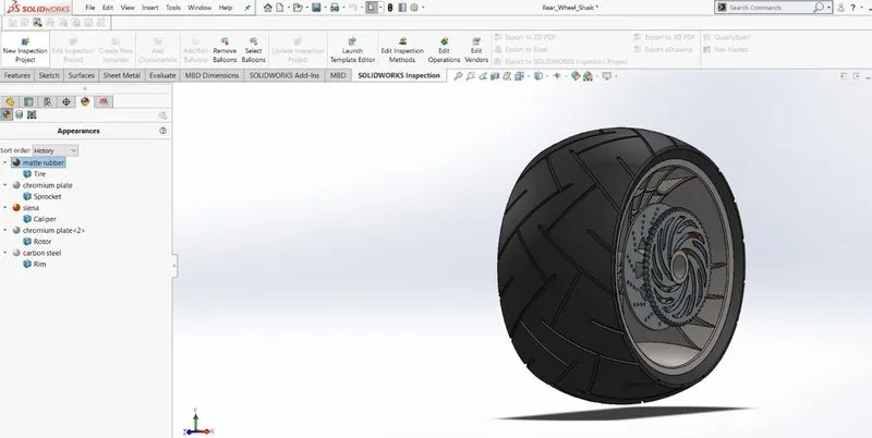
- REAR WHEEL
Just like the front wheel, the rear wheel has Rim, Tire, Caliper, Sprocket. The one end of chain is sprocket.
Some of the key features involved to create a Rear Wheel:
- Sketch
- Trim
- Revolve
- Extrude Boss
- Cut extrude
- Fillet
- Revolve cut
- Pattern
- Chamfer
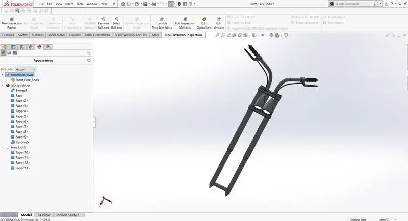
- FRONT FORK
A front fork connects a chopper’s front wheel and axle to its frame. Most forks incorporate the front suspension and front brake, and allow the front wheel to rotate about the steering axis so that the bike may be steered. Front fork has lights, handle bars, grip.
Some of the key features involved to create a Front Fork:
- Sketch
- Trim
- Revolve
- Extrude Boss
- Split
- Combine
- Dome
- Fillet
- Sweep
- Mirror
- Projected Curve
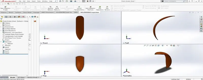
- FRONT FENDER
The primary purpose is to prevent sand, mud, rocks, liquids and other road spray from being thrown into the air by the rotating tire.
Some of the key features involved to create a Front Fender:
- Sketch
- Trim
- Offset
- Revolve
- Split
- Dynamic Mirror (Mirrored about the pre-sketched sketch entity)
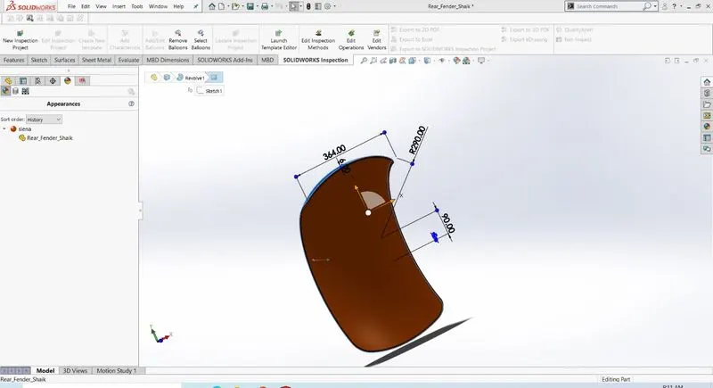
- REAR FENDER
The rear fender purpose is same as the front fender.
Some of the key features involved to create a Rear Fender:
- Sketch
- Trim
- Offset
- Revolve
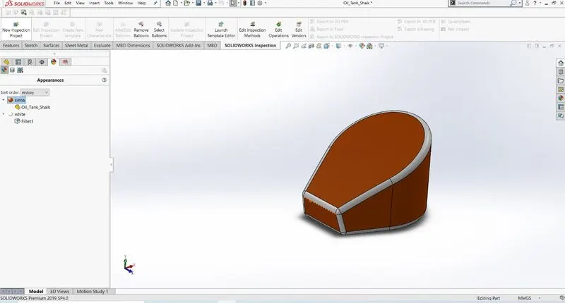
- OIL TANK
The purpose of this oil tank is to store the oil required to run the engine.
Some of the key features involved to create a Oil Tank:
- Sketch
- Extrude Boss
- Combine
- Fillet
- Shell
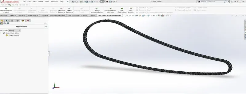
- CHAIN
It is used to transmit the motor power to the rear wheel. Proper lubricated chains can reach an efficiency of 98% or greater in the transmission.
Some of the key features involved to create a Chain:
- Sketch
- Trim
- Blocks
- Extrude Boss
- Pattern
- Fillet
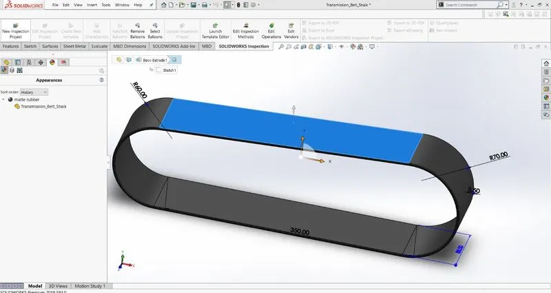
- TRANSMISSION BELT
It is used for Power transmission. Transmits power from engine to gear box.
Some of the key features involved to create a Transmission Belt:
- Sketch
- Offset
- Extrude Boss
- Fillet
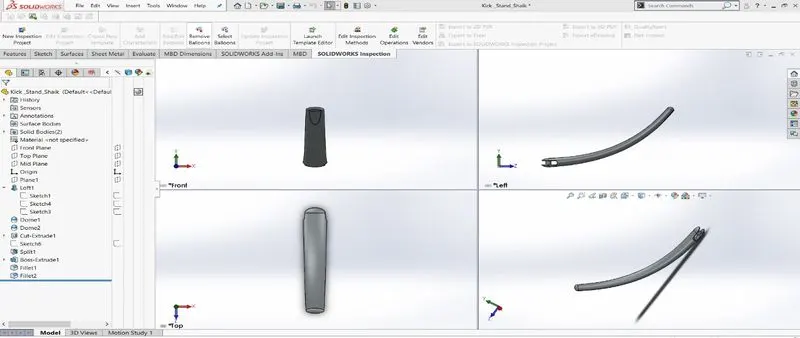
- KICK STAND
It is used that a Chopper to be kept upright without leaning against another object. It makes contact with the ground during the usage.
Some of the key features involved to create a Transmission Belt:
- Sketch
- Loft
- Extrude Boss
- Fillet
- Dome
- Split
- Extrude cut
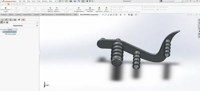
- FOOT PEDAL
The front part of right side pedal is used to apply the brake to the rear wheel and the rear part is used to place the leg on top of that for stability. It is located on both sides of the chopper.
Some of the key features involved to create a Foot Pedal:
- Sketch
- Extrude Boss
- Fillet
- Dome
- Pattern
- Chamfer
- GAS TANK:
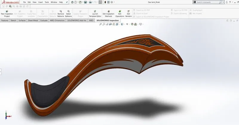
The purpose of this gas tank is to store the gas. And also acts as a top frame for the chopper.
Design: Used a ‘JPEG’ picture of American Chopper as a reference to create this part.
Some of the key features involved to create a Gas Tank:
- Sketch
- Projected Curve
- Sweep Surface
- Loft Surface
- Fill Surface
- Surface Trim
- Surface Knit
- Sweep Cut
- Fillet
ASSMEBLY
Build complex assemblies consisting of many components, which can be parts or other assemblies, called subassemblies. For most operations, the behavior of components is the same for both types. Adding a component to an assembly creates a link between the assembly and the component.
There are different types of relations, mates used in assembly to join/connect sub-assemblies to get the desired part.
Most of them are used in making the chopper assembly are: Standard mates include angle, coincident, distance, lock, parallel, perpendicular and tangent mates. In advance mates include Width mates.
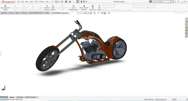
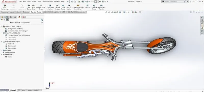
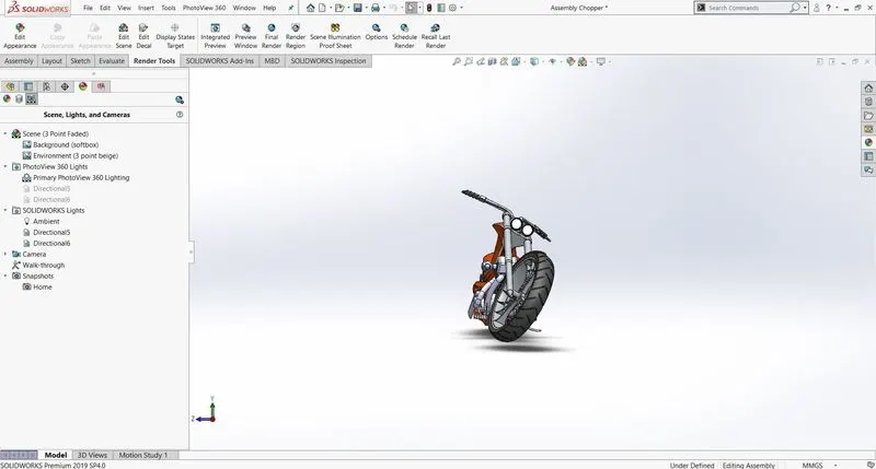
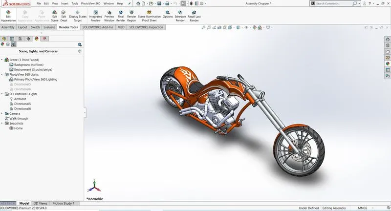
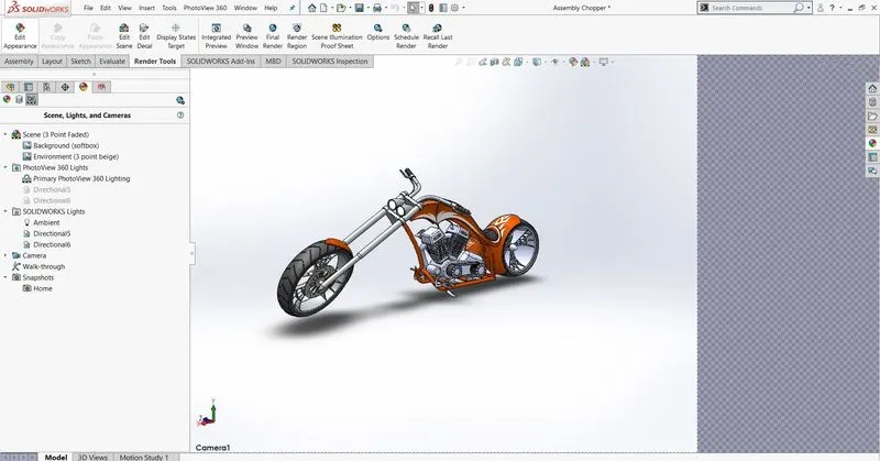
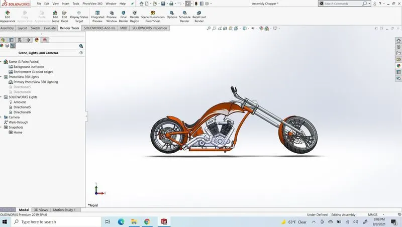
First, the chassis part was inserted into the assembly and click okay to fix the chassis in the assembly. Each part will be inserted one after another into the assembly. Using different types of mates to connect the sub-assemblies together.
ASSEMBLY TOP VIEW:
ASSEMBLY SIDE VIEW:
ASSEMBLY ISOMETRIC VIEW:
ASSEMBLY CAMERA VIEW:
ASSEMBLY FRONT VIEW:
RENDERING
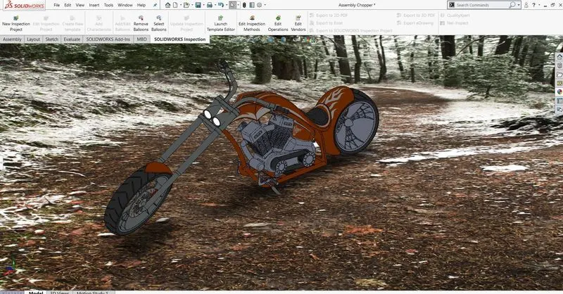
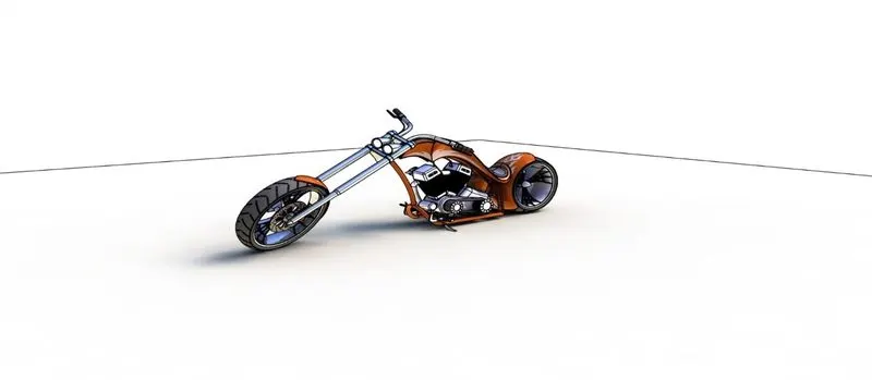
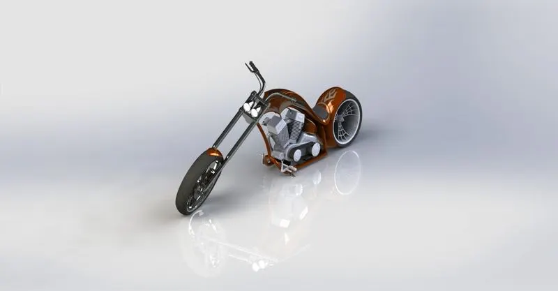
Rendering is a process of creating realistic images. PhotoView360 is a SolidWorks add-in feature that produces photo-realistic renderings of SolidWorks models. The rendered image incorporates the appearances, lighting, scene and decals included with the model.
In this process, I used Decals were added to the Gas Tank, Rear Fender, Oil Tank. Using SolidWorks visualize the appearances, scenes, camera views were changed to get a realistic image.
Some of rendered images below:
CONCLUSION:
- Created individual parts of chopper using SolidWorks
- Assembled all the individual parts to get a realistic model
- To apply the Usage of decals, lights, camera
- Used decals, lights, camera to create realistic model and rendered it using PhotoView 360